Plum ecoMAX860P3-C TOUCH Installation And Operating Manual
Regulator for automatic solid fuel fired boilers
Hide thumbs
Also See for ecoMAX860P3-C TOUCH:
Table of Contents
Advertisement
Quick Links
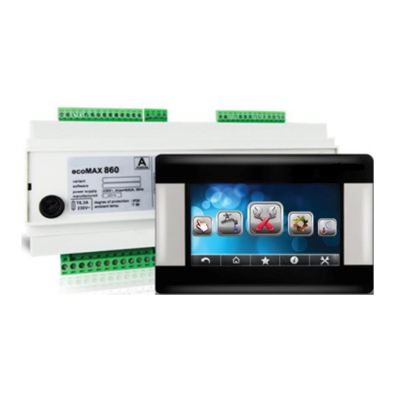
REGULATOR
ecoMAX860P3-C TOUCH
FOR AUTOMATIC SOLID FUEL FIRED BOILERS
eSTER_x80**
eSTER_x40**
ecoSTER TOUCH**
ecoSTER200**
ecoNET300**
ecoNET.apk
ecoNET.app
www.econet24.com
** the ecoSTER TOUCH or ecoSTER200 room panel, eSTER_x80 wireless room panel or
eSTER_x40 wireless thermostat and ecoNET300 Internet module isn't the standard equipment
of the regulator.
INSTALLATION AND OPERATING MANUAL
ISSUE: 1.1_EN
APPLIES TO
SOFTWARE:
MODULE
PANEL
A/B
v07.XX.XX
v07.XX.XX
functions
available
additional module B
03-2019
in
the
Advertisement
Table of Contents

Related Manuals for Plum ecoMAX860P3-C TOUCH


Summary of Contents for Plum ecoMAX860P3-C TOUCH
- Page 1 REGULATOR ecoMAX860P3-C TOUCH FOR AUTOMATIC SOLID FUEL FIRED BOILERS eSTER_x80** eSTER_x40** ecoSTER TOUCH** ecoSTER200** ecoNET300** ecoNET.apk ecoNET.app www.econet24.com functions available additional module B ** the ecoSTER TOUCH or ecoSTER200 room panel, eSTER_x80 wireless room panel or eSTER_x40 wireless thermostat and ecoNET300 Internet module isn’t the standard equipment of the regulator.
- Page 2 ELECTRIC DEVICE UNDER VOLTAGE! Before any action related to the power supply (cables connection, device installation etc.) check if the regulator is not connected to the mains! Installation should be done by a person with appropriate electrical qualifications. Improper cables connection could result in the regulator damage.
-
Page 3: Table Of Contents
TABLE OF CONTENTS 12.10 C ......29 ONNECTING EXHAUST SENSOR 12.11 W ......30 EATHER SENSORS CHECKING RECOMMENDATIONS REGARDING SAFETY ..4 12.12 O ......30 PTICAL SENSOR CONNECTION 12.13 M .... 30 IXERS ROOM TEMPERATURE CONNECTION GENERAL INFORMATION ........5 12.14 B .... -
Page 4: Recommendations Regarding Safety
dusts or liquids can cause fire or Recommendations regarding safety explosion. Thus, the regulator should be separated from flammable dusts Requirements concerning safety and gases, e.g. by means of an described in detail in individual chapters of appropriate body. this manual. Apart from them, the following requirements should particular... -
Page 5: General Information
documentation should be handed over to the General information new user / owner. controller ecoMAX860P3-C TOUCH, Applied symbols hardware version: VACC is a device designed to control the operation of a boiler with In this manual the following graphic symbols automatic feeding of solid fuel with a igniter. -
Page 7: User Settings
USER SETTINGS ecoMAX860P3-C TOUCH... -
Page 8: User Menu
• Fuel level calibration User menu Burner cleaning • Cleaning intensity Main menu • Cleaning start time Information • Cleaning stop time Boiler settings Lambda calibration* HUW settings* Night time decrease boiler Mixer 1-5 settings* • Off, Reduction value, Schedule Summer/Winter Operation with schedule HUW settings*... -
Page 9: The Controller Support
The controller support Description of the main window OPERATION Mon. Boiler temperature HUW temperature Legend: 1. Operating modes: FIRE UP, OPERATION, 9. outside temperature value (weather) SUPERVISION, BURNING OFF, functions having influence on preset CLEANING, STOP boiler temperature. Following symbols signal 2. -
Page 10: Switching On And Off The Boiler
Attention: Fuel level may be displayed on preset boiler temp. is automatically increased ecoSTER200, ecoSTER TOUCH to load the hot user water tank and power eSTER_x80, eSTER_x40 room thermostat / heating circuits of mixers. panel. FIRE UP Switching On and Off the boiler The FIRE UP mode is for automatic firing up of furnace in boiler. -
Page 11: Regulation Modes
Parameters of blow-in and exhaust output for Fuzzy Logic mode controller different power levels of the burner are automatically regulates burner power to available in the menu: allow boiler operation in such a way to Boiler settings → Output modulation maintain its temperature on preset level. -
Page 12: Burning Off
during boiler’s pauses (the furnace should Some boilers have an additional grate to not at the same fire up to too high a burn other fuels such as wood waste, etc. To temperature, because it will cause too high a activate the grid, move the parameters temperature of the boiler). -
Page 13: Huw Settings
Service settings → Burner settings → Function SUMMER activated Cleaning automatically, on the basis of readings from weather sensor. Use following parameters to 8.12 HUW settings activate this function: The controller regulates temperature of the Summer/Winter → SUMMER Mode → silo of Hot Water HUW, providing that the Auto temperature sensor is connected. -
Page 14: Weather Controlled Operation
error. room thermostat It is not recommended to use both options at the same time. traditional thermostat (NO-NC), or room panel. Upon activation of the thermostat, the Automatic correction of room temperature is preset mixer circuit temperature will be carried out in accordance with the following decreased, which, if proper decrease value is formula: selected, will stop growth of temperature in... -
Page 15: Night Decrease Settings Description
- floor heating 0,2 -0,6 be reduced automatically, without loss of - radiator heating 1,0 - 1,6 heating comfort reducing fuel - boiler 1,8 - 4 consumption. To activate time intervals, set the parameter Night time decrease for the given heating circuit to ON. The parameter Reduction value temperature... -
Page 16: Feeder Test
fuel. If the user does not add fuel, the • Calibration regulator burns all the fuel and switches off To perform calibration - fill the fuel tank to the boiler. the level corresponding to its full load and If the fuel level sensor is not used, the fuel set the parameter: level will be operated in accordance with the Boiler settings →... -
Page 17: Menu Favorites
if the device is operating correctly and if it is ecoNET.apk (Android) connected properly. Entering manual control is possible only in “Stand-by” mode, when silo is switched off. Manual control Feeder Boiler pump CHW pump Igniter OFF – the device is turned off, ON – the device is turned on. -
Page 19: Installation And Service Settings
INSTALLATION AND SERVICE SETTINGS ecoMAX860P3-C TOUCH... -
Page 20: Hydraulic Schemes
Hydraulic schemes Scheme with 4 way steering valve controlling central heating circuit : 1 – boiler with control panel, 2 – regulator, 3 – return temperature sensor, 4 – boiler temperature sensor, 5 – exhaust temperature sensor, 6 – servomotor of 4-way valve, 7 – mixer cycle pump, 8 – mixer cycle temperature sensor, 9 – HUW container, 10 –... - Page 21 Scheme with two adjustable heating circuits and the HUW container : 1 – boiler, 2 – heat exchanger, 3 – regulator, 4 – boiler temperature sensor, 5 – exhaust temperature sensor, 6 – boiler pump, 8 – HUW pump, 9 - mixer valve actuator, 10 – mixer temperature sensor, 11 – mixer pump, 12 – standard room thermostat or ecoSTER TOUCH room panel, eSTER_x40 room thermostat, 13 –...
- Page 22 Scheme with heat buffer : 1 – boiler, 2 – burner, 3 –regulator, 4 – boiler temperature sensor, 5 – exhaust temperature sensor, 6 – boiler pump, 7 – heating buffer, 8 – HUW pump, 9 - mixer valve actuator, 10 –...
-
Page 23: Technical Data
Conditions of storage and transport Technical data The regulator cannot be exposed to direct Power supply 230V~, 50Hz effects of weather, i.e. rain and sunlight. Storage and transport temperature cannot Current consumed by regulator 0,04 exceed the range of -15…+65°C. Maximum rated current 6 (6) A During transport,... -
Page 24: Mounting Of Module
Disassembly of control panel. To remove the control panel (1) from the Installation of control panel in boiler mounting plate. housing - insert flat elements (2) into indicated slots to release housing catches and remove the panel (1) 12.4 Mounting of module Working module has to be built-into the master equipment. -
Page 25: Ip Protection Rate
terminals and conductive (metallic) elements make sure that there is no voltage on of housing (min. 10 mm) is kept. terminals leads, remove Protect connecting wires from tearing, executive module enclosure. loosening and tensioning or built them in in 12.6 Connecting electrical system such a way that no load is exerted on them. - Page 26 All peripherals (such like: pumps, RE-marked relays and connected recipients) may be connected only by qualified persons in accordance with applicable regulations. Safety precautions prevent electrocution should be observed. Regulator should be equipped with a set of pins connected to the 230V AC mains.
-
Page 27: Electric Scheme
12.7 Electric scheme Scheme of electrical connections of the controller: λ –Lambda module, B – additional module, BH – upper buffer temp. sensor type CT4, BL – lower buffer temp. sensor type CT4, PLS - fuel level sensor, T – standard room thermostat type NO-NC, H – voltage output for AL alarm , RELAY –... - Page 28 Scheme of electrical connections of the additional B module: M2, M3 – mixer temp. sensor type CT4, RM2, RM3 – mixer room thermostat, L N PE - electrical power 230V~, GR – grounding strip, PM2, PM3 – mixer pump, SM2, SM3 – mixer servomotor, CPU – controlling, A –...
-
Page 29: Connection Of Temperature Sensors
under the roof. The sensor should not be 12.8 Connection of temperature sensors exposed to direct sunrays and rain. The Sensor wires may be extended using wires of sensor should be installed at least 2 m above cross-section area not less than 0.5 mm the ground far away from windows, chimneys Total length of wires of each sensor should and other sources of heat which could disturb... -
Page 30: Weather Sensors Checking
CT6-P (weather) Temp. Min. Nom. Max. °C Ω Ω Ω 901,6 901,9 902,2 921,3 921,6 921,9 960,6 960,9 961,2 999,7 1000,0 1000,3 1096,9 1097,3 1097,7 1193,4 1194,0 1194,6 1384,2 1385,0 1385,8 1478,5 1479,4 1480,3 1572,0 1573,1 1574,2 CT2S-2 (exhaust) Temp. Min. -
Page 31: Connection Of Reserve Boiler
T1 (if the ecoSTER TOUCH or eSTER_x80 Service settings → Boiler settings → room control panel is connected): Reserve boiler Service settings → Boiler settings → Deactivating control over additional boiler is Thermostat select done after setting zero value of switching off In order for the room thermostat to control for this parameter. -
Page 32: Connection Of Alarm Signalling
Note: terminals 22,21,24 have to be galvanically controller cooperates only with insulated from terminals 12,11,14 servomotors of mixing valves equipped with end switchers. Using other servomotors is 12.16 Connection of alarm signalling forbidden. Servomotors with full circle scope controller report alarms of 30 to 255s can be used. -
Page 33: Connecting Temperature Limiter
Indicator of valve position is in the menu: 12.20 Connecting of wireless room panel Information. For mixer 1 after some time it The regulator can be equipped with wireless will calibrate automatically. In order to make room panel eSTER_x80 or eSTER_x40, which the valve position indicator displaying quicker can serve as: room thermostat, boiler control the right value, disconnect the electrical... -
Page 34: Service Menu
• Extraction output 13 Service menu Grate* • Blowing power - supervision Service settings • Blowing pause - supervision Burner settings • Fan output - Grate mode Boiler settings • Extraction output - Grate mode CH and HUW settings • Automatic switch to pellet Buffer settings* Lambda sensor*... - Page 35 • CH on • Floor on • Pump only Thermostat selected* Minimum mixer temperature Maximum mixer temperature Proportional range Integration time constant Valve full opening time Pump off by thermostat Mixer input dead zone * Output H Heat exchanger cleaning •...
-
Page 36: Description Of Service Settings
14 Description of service settings 14.1 Burner Firing-up Time to check whether the burner is already firing up. Only fan is operating. If the • flame has sufficient brightness, it switches to the OERATION mode without the Ignition test time BURNING OFF mode. - Page 37 • Blowing time Duration of blowing when burning off fuel and burning off. • Blowing pause Break between airflows while burning off the fuel in burning off process. • Flame brightness with which airflow starts while burning off the fuel. Blowing start Flame brightness with which airflow starts when burning off the fuel in burning off •...
-
Page 38: Boiler
14.2 Boiler Options to choose from: • Off - deactivates room thermostat influence on boiler operation, • Universal - activates room thermostat for boiler, • ecoSTER T1 - option available after connecting room panel, boiler operation is dependant on room thermostat No1 in ecoSTER, •... -
Page 39: Buffer
protection in the form of thermostatic valves. Parameter determines how high the boiler temperature will be increased to load HUW container, buffer and mixer cycle. Temperature increase is only realizing when it is necessary. When preset boiler temperature is at sufficient level then Boiler inc. -
Page 40: Other Parameters
- allows restricting setting too high mixer preset temperature. Automatic control also will not cause exceeding preset temperature above value set in this parameter. - with parameter Mixer support = Floor ON is also limit temperature of mixer sensor when mixer pump is deactivated. For floor heating set the value below 45º…50ºC or other if producer of materials used for floor or CH installation designer state differently. -
Page 41: Alarms Descriptions
Alarm appears when feeder sensor 15 Alarms descriptions damaged or by exceeding measuring scope of this sensor. After alarm the boiler is burnt 15.1 Boiler max. temp. exceeding off. It is necessary to check the sensor and Protection against boiler overheating is done replace it if necessary. -
Page 42: No Communication
15.4 No communication stale. It consists of a periodic switching on (each 167h several seconds). This The control panel is being linked with the protects the pump against immobilization rest of the electronics with RS485 digital due to scaling. Therefore, during a break in communication link. -
Page 43: Software Update
• insert memory card (other types Plum Sp. z o. o. In order to load new memory cards are not supported) to a parameters go to: socket in the movable casing of the panel Service settings → [special password] shown above. On the memory card there and choose proper boiler/burner. -
Page 44: Producer
20 Possible faults description Symptoms Tips Check: There are no signs of operation ▪ If line fuses are not blown, replace if necessary of device despite connection to ▪ If the wire connecting panel with the executive module is plugged correctly the network. - Page 48 Wspólna 19, Ignatki 16-001 Kleosin Poland plum@plum.pl www.pum.pl...
Need help?
Do you have a question about the ecoMAX860P3-C TOUCH and is the answer not in the manual?
Questions and answers