Table of Contents
Advertisement
Quick Links
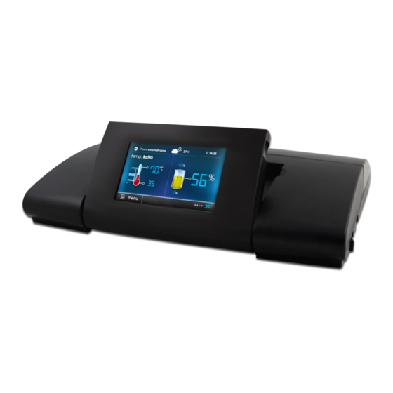
CONTROLLER
ecoMAX920P1-S TOUCH
FOR AUTOMATIC SOLID FUEL FIRED BOILERS
ecoSTER TOUCH**
ecoNET300**
ecoNET.apk
ecoNET.app
www.econet24.com
eSTER_x80**
eSTER_x40**
** Devices are not standard equipment of the controller.
INSTALLATION AND OPERATING MANUAL
ISSUE: 1.0_EN
11-2020
Functions available in
additional module B
Functions available in
additional module C
Advertisement
Table of Contents

Subscribe to Our Youtube Channel
Related Manuals for Plum ecoMAX920P1-S TOUCH


Summary of Contents for Plum ecoMAX920P1-S TOUCH
- Page 1 CONTROLLER ecoMAX920P1-S TOUCH FOR AUTOMATIC SOLID FUEL FIRED BOILERS ecoSTER TOUCH** ecoNET300** ecoNET.apk ecoNET.app www.econet24.com eSTER_x80** Functions available in additional module B eSTER_x40** Functions available in additional module C ** Devices are not standard equipment of the controller. INSTALLATION AND OPERATING MANUAL ISSUE: 1.0_EN...
- Page 2 ELECTRIC DEVICE UNDER VOLTAGE! Before any action related to the power supply (cables connection, device installation etc.) check if the controller is not connected to the mains!. Installation should be done by a person with appropriate electrical qualifications. Improper cables connection could result in the controller damage.
-
Page 3: Table Of Contents
TABLE OF CONTENTS 12.14 C ......30 ONNECTING AUXILIARY BOILER 12.15 A ......31 LARMS SIGNALING CONNECTION RECOMMENDATIONS REGARDING SAFETY ..4 12.16 M ......31 IXER SERVOMOTOR CONNECTION GENERAL INFORMATION ........5 12.17 C ......32 IRCULATION PUMP CONNECTION INFORMATION ABOUT DOCUMENTATION .. -
Page 4: Recommendations Regarding Safety
source spark high Recommendations regarding temperature, which in the presence of safety flammable dusts or liquids can cause Requirements regarding safety are described fire explosion. controller’s in detail in individual chapters of this manual. surroundings should be kept clean. Apart from them, the following requirements should in particular be followed. -
Page 5: General Information
General information - important information, failure to The controller ecoMAX920P1-S TOUCH is observe these can cause damage of designed to control the operation of a solid property, threat human fuel boiler using an optical flame brightness household animal health and life, sensor. -
Page 7: User Settings
USER SETTINGS ecoMAX920P1-S TOUCH... -
Page 8: User Menu - Structure
SUMMER mode User menu - structure Summer Winter Main menu Auto* Information Boiler settings SUMMER mode activation temp. SUMMER mode deactivation temp. HUW settings* Mixer 1-5 settings* Mixer 1-5 settings*5 Summer/Winter Preset mixer temperature General settings Alarms Mixer room thermostat Mixer weather control* Outputs test... -
Page 9: Controller Operation
Controller operation Description of the main window OPERATION Mon. Boiler temperature HUW temperature Display main window. Legend: Functions affecting preset boiler 1. Controller operation modes: FIRE UP, temperature. Following symbols signal STABILIZATION, OPERATION, respectively: SUPERVISION, BURNING OUT, BURNING - room thermostat contacts open – OFF, CLEANING, STOP preset room temperature reached, 2. -
Page 10: Switching The Boiler On And Off
parameters affecting the firing up process Switching the boiler on and off are in the menu: Make sure fuel is present in the tank and Service settings → tank hatch is closed. Now boiler may be Burner settings → Fire up switched on. -
Page 11: Operation Mode
thereby fire furnace most Power level Power level Preset temperature effectively. Preset temperature T=85° T=85° Service parameter Stabilization time determines the time to reach flame stability during firing up by the controller. After reaching flame stabilization the controller enters OPERATION mode. OPERATION mode In the OPERATION mode the burner fan operates constantly. -
Page 12: Burning Out/Burning Off Mode
in Fuzzy Logic regulation mode – after brightness dropping below Burning out end exceeding boiler preset temperature by threshold value it enters into Burning off 5ºC. mode where after expiry of Burning off time SUPERVISION mode controller the controller will shut down the boiler but oversees furnace, keeping... -
Page 13: Huw Settings
temperature drops below the value of the menu: Summer/Winter → SUMMER mode parameter: for Summer. Service settings → CH and HUW settings Attention: when boiler operates → CH pump activation temperature and without heating buffer and the then for a period of 10 minutes there has controller switched into... -
Page 14: Weather Control
In this configuration room thermostat is able Mixer settings without weather sensor. required manually desired - reduce temperature of heating cycle by a temperature in mixer’s heating cycle using constant value, when preset temperature in parameter Preset mixer temperature, e.g. a room will be reached. -
Page 15: Night Decrease Settings
thermostat = 0. In case of connected room temperature reduction in given time period – panel, temporarily following i.e. at night or when user leaves the heated parameter: Room temp. factor = 0. room. Thanks to it preset temperature can Guidelines for correct heating curve setting: be reduced automatically, without loss of - floor heating... -
Page 16: Information
Fuel level indicator support. 8.22 Information Each time when fuel silo is filled to required Menu Information enables view level it is necessary to press and keep the measured temperatures and allows to check knob in main window. Following info will which of devices are currently activated. -
Page 17: Cooperation With Internet Module
wireless room panel eSTER_x80 with thermostat function via bilateral communication, wired room panel ecoSTER200 ecoSTER TOUCH, with room thermostat function. room thermostat room panel simultaneously transmit useful information, such fuel level information, burner operation status, alarms, allows controller parameters operation modes, it also serves as an additional panel... -
Page 19: Installation And Service Settings
INSTALLATION AND SERVICE SETTINGS ecoMAX920P1-S TOUCH... -
Page 20: Hydraulic Schemes
Hydraulic schemes Scheme with 4-way steering valve controlling central heating circuit : 1 – boiler, 2 – burner, 3 – controller, 4 – boiler temperature sensor, 5 – exhaust temperature sensor, 6 – servomotor of 4-way valve, 7 – mixer cycle pump, 8 – mixer cycle temperature sensor, 9 – HUW container, 10 – HUW pump, 11 – HUW temp. - Page 21 Scheme with heat buffer : 1 – boiler, 2 – burner, 3 –controller, 4 – boiler temperature sensor, 5 – exhaust temperature sensor, 6 – boiler pump, 7 – heating buffer, 8 – HUW pump, 9 – HUW container, 10 – HUW temperature sensor, 11 - mixer valve servomotor, 12 –...
- Page 22 Scheme with heat buffer and five adjustable heating circuits :1 – boiler, 2 – burner, 3 – controller, 4 – boiler temperature sensor, 5 – exhaust temperature sensor, 6 – boiler pump, 7 – heat buffer, 8 – HUW pump , 9 – HUW container, 10 – circulation pump, 11 – three-way valve with servomotor, 12 – mixer circuit pump, 13 –...
-
Page 23: Technical Data
against damage to the STB capillary placed Technical data in the terminal box. Power supply 230 VAC, 50 Hz Controller installation Current consumed by 0,04 controller 12.1 Environmental conditions Maximum rated current 6 (6) A Due to fire risk it is forbidden to use the Controller protection rating IP 20, IP 00 controller in explosive gases atmosphere or... -
Page 24: Ip Protection Level
the furnace. the effects of the regulator, including protection against fire. Before installation wires After deactivating the controller, connection it is necessary to lead there still can be a dangerous out STB capillary from the inside of voltage on the connections. Before the terminal box to the outside of starting assembly... - Page 25 It is absolutely necessary to check connector. Cables should be put through cable outlets in the casing (1) and secured that no wire of an isolated cable or from ripping or loosening by a holdfast (5 – cable itself has no electrical contact break from casing).
-
Page 26: Electric Scheme
12.6 Electric scheme... - Page 27 Scheme of electrical connections – additional module B and C: G1 – transmission socket to connect module A, ! – connect only with two wires (do not connect with four wires as it may damage the controller and additional module), T1, T2 – mixer circuit temp. sensor type CT4, T3 – buffer upper temp. sensor type CT4, T4 –...
-
Page 28: Connection Of Temperature Sensors
12.8 Connecting the weather temp. 12.7 Connection of temperature sensor sensors The regulator cooperates only with a weather The controller cooperates only with sensors temp. sensor of the CT6-P type. The sensor of type CT4 and CT2S. The use of other should be installed on the coolest wall of the types of temp. -
Page 29: Temperature Sensors Checking
1659 1696 1733 CT6-P (PT1000) - weather Temp. Min. Nom. Max. °C Ω Ω Ω 901,6 901.9 1000,2 921,3 921.6 921,9 960,6 960.9 961,2 999,7 1000.0 1000,3 1096,9 1097.3 1097,7 1193,4 1194.0 1194,6 1384,2 1385.0 1385,8 1478,5 1479.4 1480,3 1572,0 1573.1 1574,2 CT2S (Pt1000) - exhaust... -
Page 30: Boiler Room Thermostat Connection
Service settings → Mixer 1-5 settings → Relay installation should Thermostat selection commissioned qualified person, accordingly to applicable 12.13 Boiler room thermostat regulations. connection To enable control of auxiliary boiler the Boiler circuit room thermostat may activate parameter Temperature of reserve boiler the burner or deactivate CH boiler pump. -
Page 31: Alarms Signaling Connection
signaling should be connected via terminals 30-31 of additional module B. As this output is shared with the output controlling auxiliary boiler, to activate alarm functions on this output the auxiliary control must be switched on first. To do that enter the following menu: Service settings →... -
Page 32: Circulation Pump Connection
temperature in mixer circuit is maximum (in Circulation pump may be connected to the the controller it is position 100% ON) and boiler’s controller only after buying extension valve position where mixer circuit executive module C. temperature is minimum (in the controller it is position 0% OFF). -
Page 33: Wireless Room Panel Connection
Cross-section of 12 V and GND wires to connect room panel should be at least 0,5 mm Maximum cables length should not exceed 30m. This length cannot be higher when cables with cross-section higher than 0,5 are used. Four-wires connection. Connect according to electrical scheme. -
Page 34: Service Menu - Structure
emptying time* Service menu - structure Cycle – Poker operation time*, Poker Menu available only after entering service pause*, Stoker emptying time* password Roto – Poker operation time*, Poker pause*, Stoker emptying time* Service settings Cycle x K – Poker operation time*, Burner settings Poker pause*,... - Page 35 CH pump standstill when loading HUW Minimum HUW temperature Maximum HUW temperature Boiler temp. increase from HUW and mixer Extending HUW pump operation time Circulating pump standstill time* Circulating pump operation time* Heat exchanger* Buffer settings* Buffer support Buffer loading start temperature Buffer loading end temperature Mixer 1-5 settings* Thermostat selection*...
-
Page 36: Description Of Service Parameters
Description of service parameters 14.1 Burner Parameter Description Airflow Airflow for maximum % of airflow from maximum value in Operation mode. Parameter related to Power modulation. power Airflow for medium % of airflow from medium power in Operation mode. Parameter related to Power modulation. power Airflow for minimum % of airflow from minimum power in Operation mode. -
Page 37: Boiler
Available burner cleaning modes: None – the grate mechanism operation is not included in Cleaning mode. the grate mechanism connected to output 1 in controller’s module operates VIP - continuously and is on/off cyclically according to the settings of following parameters Poker operation, Poker pause. -
Page 38: And Huw
the controller operates only with a standard room thermostat. A set of parameters available after connecting return sensor, responsible for return protection of the boiler with hydraulic installation with four-way valve equipped with mixer servomotor. It is not recommended to turn on return protection function as it may cause often supply pauses in mixer Return protection circuit. -
Page 39: Buffer
14.4 Buffer Parameter Description Parameter serves to activate buffer operating mode. It is available after connecting additional Buffer support module B and buffer temperature sensors. Buffer loading start Parameter Buffer loading start temperature defines the upper temperature of the buffer below which temperature the buffer loading process starts. -
Page 40: Other Parameters
14.6 Other parameters Parameter Description Maximum feeder Determines maximum feeder temperature at which the alarm of exceeding maximum feeder temp. temperature trips. Determines max. exhaust temp. at which the alarm of exceeding max. exhaust temp. trips. The alarm Maximum exhaust is sustained when the temperature sustains over 1min. -
Page 41: Alarms Description
The controller cannot be used as the Alarms description only boiler protection against flame Alarm numbers displayed by the wireless strike back. The additional protective eSTER_x40 room thermostat. automatics should be applied. Max. boiler temp. exceeded Alarm erase done resetting Max. -
Page 42: No Communication
15.7 No communication Insert microSD HC memory card (other card type is not supported) into indicated The control panel is connected with executive slot, placed in a movable panel housing. module via RS485 cable. In case of cable New software should be written on the damage alarm displayed. -
Page 43: Replacement Of Parts And Components
Connect the model according to electrical Control panel Executive module scheme. Probe should be enabled in the 01.xx.xxx. 01.xx.xxx.xx menu: Service settings → Burner settings → The software numbers can be read Lambda probe → Operation with Lambda rating plates probe subassemblies menu... -
Page 44: Description Of Possible Malfunctions
Description of possible malfunctions Malfunction symptoms Tips No signs of operation visible on device’s display despite Check whether mains fuses are not burned out and replace if necessary. of connecting to the network. Check: whether during that time HUW container is not loaded and preset HUW temperature is set Preset boiler temperature on display different... - Page 48 Wspólna 19, Ignatki 16-001 Kleosin, Poland plum@plum.pl www.plum.pl National Waste Disposal No: 000009381...
Need help?
Do you have a question about the ecoMAX920P1-S TOUCH and is the answer not in the manual?
Questions and answers