Table of Contents
Advertisement
Quick Links
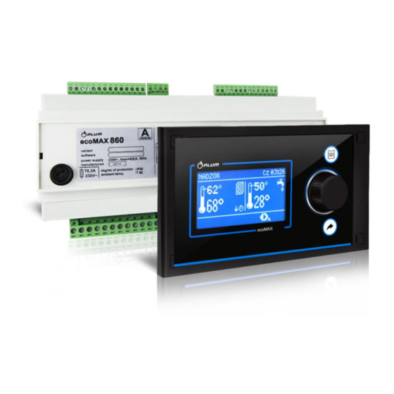
CONTROLLER
ecoMAX860P3-KL
FOR AUTOMATIC SOLID FUEL FIRED BOILERS
ecoSTER TOUCH*
ecoSTER200*
ecoNET300*
ecoNET.apk
www.econet24.com
* the ecoSTER TOUCH or ecoSTER200 room panel and ecoNET300 Internet module isn't the
standard equipment of the controller.
INSTALLATION AND OPERATING MANUAL
ISSUE: 1.1_EN_DRAFT OLNY
APPLIES TO
SOFTWARE:
MODULE
PANEL
A/B
v01.XX.XX
v01.XX.XX
functions available in the additional
module B
09-2019
Advertisement
Table of Contents

Related Manuals for Plum ecoMAX860P3-KL


Summary of Contents for Plum ecoMAX860P3-KL
- Page 1 CONTROLLER ecoMAX860P3-KL FOR AUTOMATIC SOLID FUEL FIRED BOILERS ecoSTER TOUCH* ecoSTER200* ecoNET300* ecoNET.apk www.econet24.com functions available in the additional module B * the ecoSTER TOUCH or ecoSTER200 room panel and ecoNET300 Internet module isn’t the standard equipment of the controller.
- Page 2 ELECTRIC DEVICE UNDER VOLTAGE! Before any action related to the power supply (cables connection, device installation etc.) check if the controller is not connected to the mains! Installation should be done by a person with appropriate electrical qualifications. Improper cables connection could result in the controller damage.
-
Page 3: Table Of Contents
TABLE OF CONTENTS 12.14 C ..31 ONNECTION OF BOILER ROOM THERMOSTAT 12.15 C ......31 ONNECTION OF RESERVE BOILER RECOMMENDATIONS REGARDING SAFETY ..4 12.16 C ....... 32 ONNECTION OF ALARM SIGNALING GENERAL INFORMATION ........5 12.17 C ......32 ONNECTINO OF MIXER SERVO INFORMATION ABOUT DOCUMENTATION .. -
Page 4: Recommendations Regarding Safety
dusts or liquids can cause fire or Recommendations regarding safety explosion. Thus, the controller should Requirements concerning safety be separated from flammable dusts described in detail in individual chapters of and gases, e.g. by means of an this manual. Apart from them, the following appropriate body. -
Page 5: General Information
Applied symbols General information In this manual the following graphic symbols The controller ecoMAX860P3-KL is a device are used: designed to control the operation of a boiler - useful information and tips, with automatic feeding of solid fuel with a igniter. -
Page 7: User Settings
USER SETTINGS ecoMAX860P3-KL... -
Page 8: User Menu - Structure
Fuel type User menu - structure Fuel level Alarm level Main menu Fuel level calibration Information Burner cleaning Boiler settings Lambda sensor calibration* HUW settings* Mixer 1-5 settings* HUW settings* Night time decrease Preset HUW temp. Summer/Winter HUW pump mode Operation with schedule ... -
Page 9: The Controller Support
preset boiler temperature The controller support decrease activated time Buttons description spans; - boiler preset temperature during loading the HUW container, - boiler preset temperature increase from mixer circulation; - activation of weather control for the boiler circuit; active return protection; 1. -
Page 10: The Controller Start Up
Parameters influencing firing up process are in the menu: Service settings → Burner settings → Firing-up In case of failed attempt of firing up the furnace another attempts are taken during 8.3 The controller start up which amount of fuel is reduced to 10% of After connecting the power the controller first attempt’s dose. -
Page 11: Supervision Mode
Can choose between two adjustment modes Operation in Fuzzy Logic mode responsible for stabilizing the boiler preset Fuzzy Logic mode controller temperature Standard and Fuzzy Logic. This automatically regulates burner power mode changes in the menu: allow boiler operation in such a way to Boiler settings →... -
Page 12: Burning Off Mode
to prevent the furnace from burning off Some boilers have an additional grate to during boiler’s pauses (the furnace should burn other fuels such as wood waste, etc. To not at the same fire up to too high a activate the grid, move the parameters temperature, because it will cause too high a available in the menu: temperature of the boiler). -
Page 13: Huw Preset Temperature Settings
The controller regulates temperature of the Summer/Winter → SUMMER Mode → container, providing that Auto temperature sensor is connected. When the If the automatic detection of summer mode sensor is disconnected – the information is switched on, user can set the parameters: about it is displayed in the main window. -
Page 14: Weather Control
It is not recommended to use both these Mixer settings with weather sensor possibilities at the same time. setting Automatic correction of room temperature is Set parameter Weather mixer control in done according to formula: position on. Adjust weather curve according Correction = (preset room temperature –... -
Page 15: Night Decrease Settings Description
indicated by the symbol on the main screen. To activate time intervals, set the parameter Night time decrease for the given heating circuit parameter Reduction value temperature reduction, one for all time intervals. Night time decreases can be defined separately for every day of the week set Schedule. -
Page 16: Fuel Level Configuration
defined time periods circular pump Description of activity deactivated. In omitted periods the circular The controller measured fuel level on the pump is switched into position Circulating basis of its current consumption. Factory operation time, what Circulating standstill settings will not always correspond to actual time. -
Page 17: Manual Control
8.26 Manual control In the controller it is possible to manual activate devices like i.e. pumps, feeder engine, or blower engine. It enables to check if the device is operating correctly and if it is connected properly. Entering manual control is possible only in “Stand-by”... -
Page 19: Installation And Service Settings
INSTALLATION AND SERVICE SETTINGS ecoMAX860P3-KL... -
Page 20: Hydraulic Schemes
Hydraulic schemes Scheme with 4 way steering valve controlling central heating circuit : 1 – boiler with control panel, 2 – controller, 3 – return temperature sensor, 4 – boiler temperature sensor, 5 – exhaust temperature sensor, 6 – servomotor of 4-way valve, 7 – mixer cycle pump, 8 – mixer cycle temperature sensor, 9 – HUW container, 10 –... - Page 21 Scheme with two adjustable heating circuits and the HUW container : 1 – boiler, 2 – heat exchanger, 3 – controller, 4 – boiler temperature sensor, 5 – exhaust temperature sensor, 6 – boiler pump, 7 – HUW container, 8 – HUW pump, 9 - mixer valve actuator, 10 – mixer temperature sensor, 11 – mixer pump, 12 –...
- Page 22 Scheme with heat buffer : 1 – boiler, 2 – control panel, 3 – controller, 4 – boiler temperature sensor, 5 – exhaust temperature sensor, 6 – boiler pump, 7 – heating buffer, 8 – HUW pump, 9 - mixer valve actuator, 10 –...
-
Page 23: Technical Data
During transport, device cannot 10 Technical data exposed to vibrations greater than those Power supply 230V~, 50Hz typical of normal road transport. Current consumed by controller 0,04 Maximum rated current 6 (6) A 12 Controller installation Controller protection rating IP 20 12.1 Environmental conditions Ambient temperature 0...50C... -
Page 24: Mounting Of Module
Fitting the controller in a mounting plate: 1 – control panel, 2 – sheet metal screw 2.9x13, 3 – hole plug. Step 2: Remove the lid (5), plug the cable (6) and put the lid (5) back on, securing it with screws (4). -
Page 25: Ip Protection Rate
placing the module on the rail, lift up the from the front side of the executive module enclosure (specified on the rating plate). catch. Now, place the module on the rail and From the side of the terminals, the casing press the catch to bring it to the original has protection rate IP00, thus the terminals position. - Page 26 (L) and neutral (N) wires. Make sure that the L and N conductors exchanged within building's electrical system, e.g. in electrical socket electrical socket junction box! All peripherals (such like: pumps, RE-marked relays and connected recipients) may be connected only by qualified persons in accordance with applicable regulations.
-
Page 27: Electric Scheme
12.7 Electric scheme Scheme of electrical connections of the controller: λ –Lambda module, B – additional module, BH – upper buffer temp. sensor type CT4, BL – lower buffer temp. sensor type CT4, PLS - fuel level sensor, T – standard room thermostat type NO-NC, H –... - Page 28 Scheme of electrical connections of the additional B module: M2, M3 – mixer 2 and 3 temp. sensor type CT4, RM2, RM3 – mixer 2 and 3 room thermostat, L N PE - main power 230 VAC, GR – grounding strip, FU –...
-
Page 29: Connection Of Temperature Sensors
12.9 Connection of weather temperature 12.8 Connection of temperature sensors sensor The controller works only with CT4 sensors. controller cooperates only with other types sensors weather sensor of the CT6-P type. prohibited. The sensor should be installed on the coolest Sensor wires may be extended using wires of wall of the building. -
Page 30: Temperature Sensors Checking
1659 1696 1733 CT6-P (weather) Temp. Min. Nom. Max. °C Ω Ω Ω 901,6 901,9 902,2 921,3 921,6 921,9 960,6 960,9 961,2 999,7 1000,0 1000,3 1096,9 1097,3 1097,7 1193,4 1194,0 1194,6 1384,2 1385,0 1385,8 1478,5 1479,4 1480,3 1572,0 1573,1 1574,2 CT2S-2 (exhaust) Temp. -
Page 31: Connection Of Boiler Room Thermostat
parameter Thermostat select. is correctly Assembly of relay should be chosen in the menu: done by a person with proper Service settings → Mixer settings 1-5 qualifications. According to valid norms and regulations. 12.14 Connection of boiler room To enable the control of reserve boiler, set thermostat the H output to operate the reserve boiler in Boiler circuit room thermostat may activate... -
Page 32: Connection Of Alarm Signaling
Example connection external alarm annunciator. 1 - controller , 2 – external alarm annunciator, 3 – relay. 12.17 Connectino of mixer servo During assembly works for mixer servomotor pay attention not to overheat the boiler. This may happen when there is a limited flow of water from the boiler. -
Page 33: Connection Of Stb Temperature Limiter
position in which temperature in mixer Cross-section area of wires used to circuit is maximal (in controller it is connect room panel should be 0,75 position 100% ON) and value position when temperature of mixer circuit is Max. length of wires should not exceed 30 m. minimal (in controller it is position 0% This length may be longer if the wires used OFF). -
Page 34: Service Menu - Structure
Exh.fan output 13 Service menu – structure Grate* Entering the service menu requires Fuel detection time entering the service password. Flush time Service settings Flush interval Burner settings Auto switch to pellet Boiler settings Lambda sensor* CH and HUW settings ... - Page 35 CH on Floor on Pump only Thermostat selected* Universal ecoSTER T1…T3 Min. mixer temp. Max. mixer temp. Proportional range Integration time constant Valve opening time Pump off by therm. Mixer input dead zone * Output H Cleaning Alarm...
-
Page 36: Description Of Service Parameters
14 Description of service parameters 14.1 Burner Parameter Description Firing-up Time to check whether the burner is already firing up. Only fan is operating. If the flame has Ignition test time sufficient brightness, it switches to the OERATION mode without the BURNING OFF mode. ... -
Page 37: Boiler
feeding fuel in Supervision mode with low fumes emission. Exhaust fan power during operation in Supervision mode. Adjust value in such a way to burn Exh.fan output feeding fuel in Supervision mode with low fumes emission. Grate In this mode automatic fuel feeding is off. Fuel shortage detection time after the exhaust gas temperature drops, when operating in grate ... -
Page 38: And Huw
temperature exceeds maximum value. The controller will not open mixer cycle when Mixer support = Floor ON. Options available: Off burner - the burner will be turned off when the room thermostat of the boiler operates, without switching off the boiler pump. ... -
Page 39: Other Parameters
Mixer support Off Mixer servomotor and pump are not active. Applicable when mixer cycle powers heating installation of CH. Maximum temperature of mixer cycle is not limited, mixer is fully opened during alarms i.e. boiler overheating. Attention: do not ... -
Page 40: Alarms Descriptions
15 Alarms descriptions 15.4 Feeder temp. sensor damage Alarm appears when feeder sensor 15.1 Boiler max. temp. exceeding damaged or by exceeding measuring scope Protection against boiler overheating is done of this sensor. After alarm the boiler is burnt in 2 steps. In the first step , after exceeding off. -
Page 41: Firing Up Failed Attempt
No communication”. The controller doesn’t 16.3 Pump antistandstill function stop to operate and works normally with The controller does the function of CH, HUW before preset parameters. It is required to and Mixer pumps protection against getting check the connection cable between control stale. -
Page 42: Lambda Sensor
Default settings for given boilers / connecting additional lambda sensor module. burners should be consulted with Company Lambda sensor is to be activated in the Plum Sp. z o. o. In order to load new menu: parameters go to: Service settings → Burner settings →... -
Page 43: Possible Faults Description
20 Possible faults description Symptoms Tips Check: There are no signs of operation of if line fuses are not blown, replace if necessary, device despite connection to the if the wire connecting panel with the executive module is plugged correctly and if network. - Page 48 Wspólna 19, Ignatki 16-001 Kleosin Poland plum@plum.pl www.pum.pl...
Need help?
Do you have a question about the ecoMAX860P3-KL and is the answer not in the manual?
Questions and answers