Table of Contents
Advertisement
Quick Links
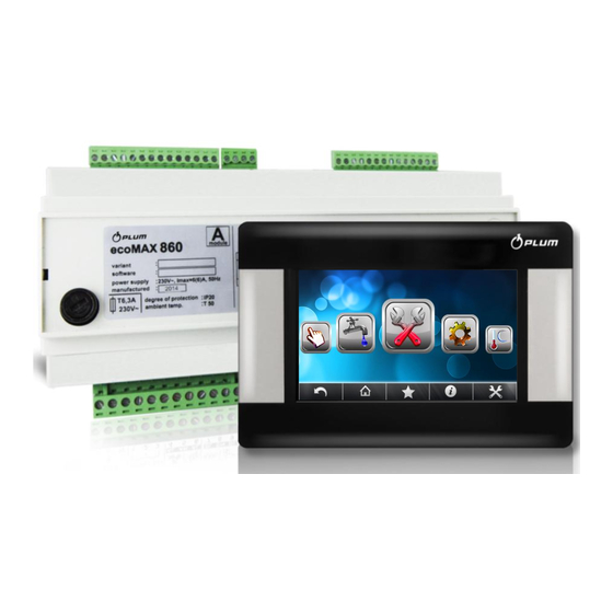
Boiler controller
ecoMAX860P3-D TOUCH
FOR AUTOMATIC SOLID FUEL FIRED BOILERS
ecoSTER TOUCH**
ecoNET300**
ecoNET.apk
www.econet24.com
** room panel ecoSTER TOUCH and internet module ecoNET300 - not the standard equipment of the
controller.
INSTRUCTION INSTALLATION AND OPERATING MANUAL
ISSUE: 1.0
APPLIES TO SOFTWARE:
MODULE A
PANEL
v01.XX.XX
v.01.XX.XX
05-2016
functions available in the
additional module B
Advertisement
Table of Contents

Related Manuals for Plum ecoMAX860P3-D TOUCH


Summary of Contents for Plum ecoMAX860P3-D TOUCH
- Page 1 Boiler controller ecoMAX860P3-D TOUCH FOR AUTOMATIC SOLID FUEL FIRED BOILERS ecoSTER TOUCH** ecoNET300** ecoNET.apk www.econet24.com functions available in the additional module B ** room panel ecoSTER TOUCH and internet module ecoNET300 - not the standard equipment of the controller. INSTRUCTION INSTALLATION AND OPERATING MANUAL ISSUE: 1.0...
-
Page 3: Table Of Contents
CONTENTS RECOMMENDATIONS REGARDING SAFETY ..4 HYDRAULIC DIAGRAMS ........22 GENERAL ............. 5 11.1 1 ............22 IAGRAM INFORMATION ABOUT DOCUMENTATION ..5 11.2 2 ............23 IAGRAM STORAGE OF DOCUMENTATION ......5 11.3 3 ............24 IAGRAM APPLIED SYMBOLS ..........5 TECHNICAL DATA .......... -
Page 4: Recommendations Regarding Safety
means that case RECOMMENDATIONS REGARDING malfunction it can be the source of a spark or high temperature, SAFETY which presence flammable dusts or liquids can Requirements concerning safety cause fire or explosion. Thus, described in detail in individual chapters of regulator should this manual. -
Page 5: General
Applied symbols General In this manual the following graphic symbols The regulator is a modern electronic device are used: designed to control automatic solid fuel fired boilers with ignition. - useful information and tips, Flame detection occurs with an optical flame brightness sensor. -
Page 7: Instruction Manual
INSTRUCTION MANUAL ecoMAX860P3-D TOUCH... -
Page 8: Structure - Main Menu
HUW settings* STRUCTURE – MAIN MENU HUW preset temperature HUW pump mode Main menu Information Priority Boiler settings No priority HUW settings* HUW container hysteresis Summer/Winter HUW disinfection Mixer 1-5 settings* Night time decrease HUW General settings ... -
Page 9: Operating The Regulator
Operating the regulator Description of display main window OPERATION Legend: - of preset boiler temperature for 1. mode of regulator operation: FIRING-UP, active time intervals INCANDESCENCE, OPERATION, SUPERVISION, BURNING OFF, - increase of preset boiler temperature CLEANING, STOP for the time of HUW container filling 2. -
Page 10: Switching On And Off The Boiler
If firing up the furnace fails, further attempts Switching on and off the boiler are carried out during which the fuel dose (feeding time) is reduced to 10% of the dose Make sure fuel is present in the tank and in the first attempt. -
Page 11: Regulation Mode
Regulation mode mode does not require setting the H1 and H2 hysteresis. There regulation modes If only the HUW is heated (summer stabilizing the set temperature of the boiler: mode), it is recommended to set the Standard and FuzzyLogic regulator to Standard mode. Boiler settings →... -
Page 12: Burning Off
The controller exits the Supervision mode if the boiler is set to work with a buffer - decrease upper buffer temperature without user intervention after exceeding the below the preset value (Loading start preset boiler temperature of 10 ° C. temperature). -
Page 13: Setting Huw Preset Temperature
8.14 Setting HUW preset temperature Service settings → CH and HUW settings Preset temperature defined Setting circulating pump control parameter: analogical night decrease setting. HUW settings → HUW preset temp. Circulating pump switches on in selected Below HUW preset temp. – HUW container time intervals. -
Page 14: Weather Controlled
In this setup, it is possible to connect a room It is necessary to find appropriate value of thermostat which will equalize the inaccuracy the Room temp. coeff. Range: 0…50. The of selecting heating curve, if the selected higher coefficient, greater heating curve value is too high. -
Page 15: Description Of Night Time Decrease Settings
- if the outdoor temperature drops, and the 8.20 Description of night time decrease room temperature increases, the selected settings heating curve value is too high, - if the outdoor temperature drops, and the Boiler night time decreases room temperature drops as well, the selected boiler operates selected... -
Page 16: Feeder Efficiency Test
Note: When there is no fuel level The indicator in the main window will be set sensor, fuel level service will take to 100%. On-going calibration process is place as described below. signalled by flashing fuel level gauge. The Activating the fuel level gauge gauge will flash until the time of marking the In order to enable display of the fuel level,... -
Page 17: Favourite Menu
Access to manual control menu is exceeding Boiler cooling temperature the possible only in the STAND-BY controller is trying to lower the temperature mode, i.e. when the boiler is OFF. by directing overheated water to the HUW Long-term operation of the fan, the tank and also by opening mixer actuators feeder or other working equipment (only when Mixer support = CH On). -
Page 18: Boiler Temperature Sensor Damage
Boiler overheating STB open The regulator cannot be used as contact the only flame return protection. alarm occurs after activation additional automatic independent safety thermostat that secures protection. the boiler against overheating. The burner will then be deactivated. After the boiler Boiler temperature sensor temperature will drop down it is required to damage... -
Page 19: Function Of Protecting Pumps Against
using Lambda sensor readings. The amount Note: This function must not be of air provided to the furnace will be the only anti-freezing protective automatically set in such a way to obtain measure! Apply other methods preset amount of air in fumes. If this too. -
Page 21: Installation And Service Settings
INSTALLATION AND SERVICE SETTINGS ecoMAX860P3-D TOUCH... -
Page 22: Hydraulic Diagrams
11 Hydraulic diagrams 11.1 Diagram 1 Diagram with 4-way control valve for central heating circuit , where: 1 – boiler, 2 – controller, 3 - water temperature sensor returning to the boiler CT4, 4 – boiler temperature sensor CT4, 5 – exhaust temperature sensor CT2S (temperature monitoring only), 6 –... -
Page 23: Diagram 2
11.2 Diagram 2 Diagram with two adjustable heating circuits and the HUW container , where:1 – boiler, 2 – heat exchanger, 3 – controller, 4 – boiler temperature sensor, 5 – exhaust temperature sensor (temperature monitoring only), 6 – boiler pump, 8 – HUW pump, 9 – HUW container, 10 – HUW temperature sensor, 11 – mixer pump, 12 –... -
Page 24: Diagram 3
11.3 Diagram 3 Diagram with heat buffer , where:1 – boiler, 2 – panel controller, 3 – controller, 4 – boiler temperature sensor CT4, 5 – exhaust temperature sensor CT2S, 6 – boiler pump, 7 – heat buffer, 8 – HUW pump , 9 - mixing valve actuator, 10 - mixer temperature sensor CT4, 11 - mixer pump, 12 - upper sensor of buffer temperature CT4, 13 - lower sensor of buffer temperature CT4, 14 - ecoSTER200/ecoSTER TOUCH room control panel, 15 - thermostatic three-way valve to the return protection, 16 - out-door temperature... -
Page 25: Technical Data
REGULATOR INSTALLATION Technical data 14.1 Environmental conditions Voltage 230V~; 50Hz; Due to the risk of fire is prohibited to use the Current consumed by regulator 0,04 A controller explosive dust Maximum rated current 6 (6) A enviroment (eg coal). Regulator should be Regulator protection rating IP20 separated using appropriate enclosure. -
Page 26: Mounting Of Working Module
Drill a hole in the mounting plate acc. the below drawing. To remove the control panel (1) from the housing - insert flat elements (2) into indicated slots to release housing catches and remove the panel (1). 14.4 Mounting of working module Working module has to be built-into the master equipment. -
Page 27: Ip Protection Rate
Space requirements working module mounting. Methods of module installation: a – in modular housing with access to front surface, b – in the cover without access to front surface, 1- working module, 2 – DIN TS35 rail, 3 – catch. 14.5 IP protection rate Enclosure regulator’s... -
Page 28: Connecting Electrical System
14.6 Connecting electrical system Regulator is designed to be fed with 230V~, 50Hz voltage. The electrical system should be: three core (with protective wire), in accordance with applicable regulations. Caution: After the regulator is turned off using the keyboard, dangerous voltage can occur on the terminals. -
Page 29: Electric Scheme
14.7 Electric scheme Wiring diagram controller ecoMAX860P3-D TOUCH: λ – Lambda sensor module, B – B module to support additional heat circuits, BH – upper buffer temperature sensor type CT4, BL – lower buffer temperature sensor type CT4, PLS – fuel level sensor, T – standard room thermostat, H – output for alarm device or reserve boiler, RELAY –... - Page 30 M2 – regulated circuit (mixer 3) sensor temperature type CT4, RM2 – mixer 2 room thermostat, RM3 – mixer 3 room thermostat. L N PE - power supply 230V~, GR – grounding bar, PM2/PM3 – mixer 2/3 pump, SM2/SM3 – mixer 2/3 servo, CPU – controller, A – ecoMAX860P3-D TOUCH regulator module A.
-
Page 31: Connection Of Temperature Sensors
the leads is insignificant. Connect the other 14.8 Connection of temperature end of the cable to the regulator. sensors Attach the sensor to the wall using tackbolts. Sensor wires may be extended using wires of To access the tackbolts holes, unscrew the cross-section area not less than 0.5 mm sensor lid. -
Page 32: Connection Of Mixers Room Thermostat
with the technical documentation of this °C Ω Ω Ω 901,6 901,9 902,2 boiler. 921,3 921,6 921,9 The reserve boiler should be connected via 960,6 960,9 961,2 relay to terminals 46-47. 999,7 1000,0 1000,3 1096,9 1097,3 1097,7 1193,4 1194,0 1194,6 1384,2 1385,0 1385,8... -
Page 33: Connection Of Alarm Signalling
Connection of an external alarm annunciator. 1- regulator , 2 – external alarm annunciator, 3 – relay. 14.15 Connection of mixer When connecting mixer servo, take due care to prevent boiler overheating, which occur when the flow of boiler water is limited. -
Page 34: Connecting Temperature Limiter Stb
which the temperature in mixer circuit is Max. length of wires should not exceed 30 m. maximum and minimum (it corresponds to This length may be longer if the wires used the setting of the regulator of "100% ON" have cross-section area larger than 0,5mm "0% OFF, respectively). -
Page 35: Service Menu
Parameter A,B,C Lambda 15 Service menu Minimum airflow output Fuel shortage detection time Max. burner temperature Service settings Operation time of external feeder Burner settings Boiler settings Boiler settings CH and HUW settings Buffer settings* Thermostat select Mixer 1-5 settings* ... - Page 36 Reserve Boiler Alarms * unavailable if no adequate sensor or additional module is connected or the parameter is hidden.
-
Page 37: Service Settings
16 SERVICE SETTINGS 16.1 BURNER Firing-up It is a verification time to check, if the furnace is burning or not. In this Ignition test time time only ventilator is working. The basic amount of fuel that will supply feeder at the first attempt firing- ... -
Page 38: Boiler
Supervision time = 0, then the controller skip the SUPERVISION mode and goes directly to BURNING OFF mode. When the parameter Supervision time = 255, then the controller stays in SUPERVISION mode until the boiler temperature drops down up to the level, by which the controller returns to OPARATION mode. -
Page 39: And Huw
The boiler return temperature below which the electric actuator will close Min. return temperature the mixing valve. It is a value for opening the mixing valve during active return protection function. This value is given in percentage. This value should be set in such way, that the return temperature can raise. -
Page 40: Buffer
controller will not change this temperature with the necessity of loading the HUW tank, buffer or mixer circuit. Allows for removal of heat from boiler by HUW feed. directly after the Extending HUW pump operation HUW feed. is load. In order to cool the boiler, the oper. of HUW pump time can be extended by a period of extended oper. -
Page 41: H Output
allows you to select room thermostat for mixer. Options to choose from: OFF - disables the thermostat. Universal - standard thermostat, connected to terminals 44-45 for mixer 1, for 2-5 mixers are suitable terminals in additional modules. ecoSTER T1-T3 - thermostat in the room panel ecoSTER TOUCH. -
Page 42: Othtrs
Operation alarms when the parameter Reserve boiler set to zero. 16.7 OTHTRS Available options: YES - shows hidden parameters, which edition is not Show advanced setup recommended. NO - hides hidden parameters. Restoring service settings will also restore the settings from the main Restore default settings menu (the user). - Page 44 Wspólna 19, Ignatki 16-001 Kleosin, Poland phone +48 85 749-70-00 fax +48 85 749-70-14 plum@plum.pl www.plumelectronics.eu...
Need help?
Do you have a question about the ecoMAX860P3-D TOUCH and is the answer not in the manual?
Questions and answers