Table of Contents
Advertisement
Quick Links
THE CONTROLLER WITH BALANCED VENTILATION FUNCTION
ecoVENT MIDI
FOR CONTROLLING VENTILATION CENTRAL WITH MECHANICAL RECUPERATOR
ecoNET300*
www.econet24.com
ecoNET.apk
simTOUCH2
ecoTOUCH
ecoPRESS EX1*
GHE
* is not a standard controller equipment.
INSTALLATION AND OPERATING MANUAL
ISUUE: 1.3_EN
SOFTWARE VERSION: 03.xx
12-2019
Advertisement
Table of Contents

Related Manuals for Plum ecoVENT MIDI


Summary of Contents for Plum ecoVENT MIDI
- Page 1 THE CONTROLLER WITH BALANCED VENTILATION FUNCTION ecoVENT MIDI FOR CONTROLLING VENTILATION CENTRAL WITH MECHANICAL RECUPERATOR ecoNET300* www.econet24.com ecoNET.apk simTOUCH2 ecoTOUCH ecoPRESS EX1* * is not a standard controller equipment. INSTALLATION AND OPERATING MANUAL ISUUE: 1.3_EN SOFTWARE VERSION: 03.xx 12-2019...
- Page 2 ELECTRIC DEVICE UNDER VOLTAGE! Before any action related to the power supply (cables connection, device installation etc.) check if the controller is not connected to the mains! Installation should be done by a person with appropriate electrical qualifications. Improper cables connection could result in the controller damage.
-
Page 3: Table Of Contents
TABLE OF CONTENTS 13.3 .......... 36 EAD REQUEST 13.4 ......36 ODIFICATION REQUEST Safety recommendations ........4 13.5 ......37 ODIFICATION REQUEST General information ........... 5 13.6 ..........38 ODBUS TABLE Information about documentation ..... 5 INSTALLER MENU - STRUCTURE ...... -
Page 4: Safety Recommendations
Safety recommendations • The controller has following procedures: turning off heater while overheating, which protects water heaters against Requirements concerning safety are freezing, it disables fans when alarms described in detail in individual chapters of occur, however elements used must this manual. -
Page 5: General Information
General information Applied symbols The ecoVENT MIDI controller controls the In this manual the following graphic symbols recuperator of mechanical ventilation with a are used: cross-flow or rotary exchanger. Performs the function of heat recovery from ventilated rooms based on readings from sensors and The symbol means useful information and has the function of balanced ventilation. -
Page 7: User Manual
USER MANUAL ecoVENT MIDI... -
Page 8: Operating The Controller
Operating the controller Winter opening temp. Regeneration settings User menu – structure • Maximum opening time • Regeneration time • Manual start The ecoTOUCH panel: Operation modes device Filters* Recuperator operation mode • Override filters replacement procedure Main mode - No, Yes - Pause •... - Page 9 • Screen saver settings Winter mode activation • On/Off screen saver • Hyst. of turn. on summer mode • Time till screen saver • 1…4 User mode • Screen saver backlight ➢ Preset temperature Button sound ➢ Air supply fan speed Alarms sound ➢...
-
Page 10: Controlling The Controller
ecoNET settings ➢ WiFi encryption type ➢ WiFi Name ➢ WiFi Password Address settings Brightness Contrast Language Date and Clock Default settings Panel software update Controller software update Selection and edit in the menu is done by Alarm system settings pressing desired symbol on the screen. -
Page 11: Switching Controller On And Off
To start the controller, press anywhere on the screen, then the following message will - enter selected menu option or accept appear: “Turn on the recuperator?”. selected parameter setting. - decrease or increase value of the on-screen selected parameter. The simTOUCH2 panel: The controller is operated via touch buttons that allow selecting items from the menu and edition of parameters. -
Page 12: Main Screens
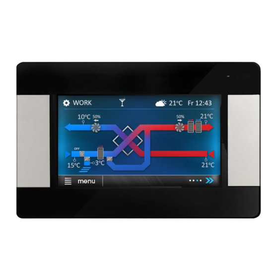
Main screens The ecoTOUCH panel: The controller has two main screens. First: with the displayed parameters and operation modes, with the function of editing and reading information, second: with automation scheme displayed. The view between these screens can be switched. Main screen with options to read information and change selected parameters. - Page 13 Main screen with rotary exchanger Automation schemes presented on the main screen can be different depending on whether there are individual ventilation system devices connected to the controller e.g.: throttles, heaters, and values display are for information purposes only. Legend: 1.
-
Page 14: Controller Operation Modes
The simTOUCH2 panel: 8. Operation modes: Pause, Mode 1…4 controller main screens: (U1...4). information screen with basic parameters and 9. Information: automation scheme screen. Switching - summer mode active between screens is done by touching the (2) and (5) buttons. - fireplace mode. -
Page 15: Device Operating Modes
then depending on fulfilling conditions, presence of large number of people in the starts the cooler. room. • Defrosting – controller prevents - Airing mode: amends exhaust fan exchanger to freeze, by adjusting fans expenditure, while turning off air supply speed and starting primary heater. -
Page 16: User Modes
• Time modes settings – menu allows to define time modes settings, for Airing The balanced ventilation function requires the mode it is possible to set mode duration connection of differential pressure sensors. time (Duration time parameter), preset The function turn on and configuration is done temperature (Preset temp. -
Page 17: Support Of Bypass
from external temperature sensor • Alarm central support – turns on/off alarm readings. central support. If the function is active, Additional GHE control settings are in the then after receiving signal from alarm menu: central the controller operation will be Menu →... -
Page 18: Exchanger Cleaning
Icon allows to copy currently defined schedule to any day of the week. Res icon clears set schedule. 7.12 Exchanger cleaning Cleaning start hour parameter allows setting the moment to start cleaning. The procedure will be started at the preset hour after reaching cleaning day. -
Page 19: Internet Module Cooperation
Screen saver mode, can select the screen saver mode for: Off, On or Clock. • ecoNET settings – WiFi network To ensure the correct system operation the configuration in case of connection an control panel addresses must from internet module ecoNET300 address pool 100…132. - Page 21 The following is the appearance of the website and the mobile application for remote operation of the ventilation system with exemplary work parameter values. Main current data. Installation ventilation scheme. Data history graph.
-
Page 22: Alarms And Promps
Mobile application interface. 7.15 Alarms and promps Working in the emergency state is allowed only under your supervision until the arrival of the service and rectify the fault. If the user's supervision is not possible, the controller should be disconnected from the power supply. Alarm Possible cause Due to an alarm... - Page 23 The air supply filter counter supply filter Continually since the exceeded value preset with replacement deadline Signaling alarm occurrence Filter replacement deadline approaching cause of the alarm. alarm. exhaust filter counter Exhaust filter Continually since the exceeded value preset with replacement deadline Signaling alarm...
-
Page 24: Cooperation With Air Parameters Sensors
Cooperation with parameters concentration, controller will immediately sensors lower fans speed. It will provide lowering the controller integrated software amount of outdoor air intake, resulting in modules allowing cooperation of recuperation successive increase of CO concentration. central with selected types of air parameters When CO concentration in the air reaches sensors: digital carbon dioxide level sensor... -
Page 26: Installation And Service Settings
INSTALLATION AND SERVICE SETTINGS ecoVENT MIDI... -
Page 27: Automation Schematics
Automation schematics The following sample schemes automation does not replace the design of ventilation systems. It is used only as an example! Ventilation diagram with cross-flow exchanger (or countercurrent) and secondary freon or water cooler, and secondary electric heater. Ventilation diagram with rotary exchanger and secondary freon or water cooler or primary and secondary electric heater. - Page 28 enclosing of the controller module, 25 – mixer chamber intake actuator, 26 – intake filter, 27 – extraction filter, 28 - differential pressure sensors, 29 - air quality sensor, 30 - laminar flow limiter. Brief description of the operation with cross-flow exchanger. In the moment of turning on the controller, throttles of air supply and extraction are opened by actuators, next the air supply and exhaust fans start to work.
-
Page 29: Technical Data
10 Technical data transport. Do not use the controller under steam condensation conditions, protect from The controller power 230 V~,50 Hz water. Storage and transport temperature supply should not exceed the range of Current consumption 0,04 -25…+50°C. Install in a dry place. Max. - Page 30 The ecoTOUCH panel: Drill holes in the wall (2) and screw in the screws (3). Then connect the controller’s panel (1) with a wire, that can be placed in wall’s hollow or on its surface (4). Installation requirements: 1 – control/room panel, A rectangular mounting hole can also be cut 2 –...
-
Page 31: Main Module Installation
Insert the wires of the cable into the socket in the cover (2). When installing the control panel, follow the steps below. STEP 1 Screw the cover (2) to the wall with screws (4 mm x 2.9 mm x 13 mm), necessarily in the orientation according to the figure below. -
Page 32: Cleaning And Maintenance Procedures
Keep safe spacing between module terminals and conducting casing elements min. 10 mm. An example of a metal enclosing of the module is shown in the figure below. The minimum required spacing is given. Assembly dimensions of the module are shown in the further part of the manual. -
Page 33: Electrical Connection
Connect the PE protective wire with module PE It is not allowed to clean the device by input and housing terminal and protective spraying water or other liquids on it. If the cables of connected devices. liquid gets inside the device it can cause fire, electrocution or damage to the device. -
Page 34: Electrical Scheme
12.5 Electrical scheme ecoTOUCH panel simTOUCH2 panel Analog outputs (NTC 10K): T1 – temp. sensor behind exchanger (optional) W1 – air supply fan T2 - supply temp. sensor (required) W2 – exhaust fan T3 – extraction temp. sensor (required) GWC – GHE throttle actuator T4 –... - Page 35 The controller allows free outputs configuration depending in used ventilation central. electrical diagram shows default outputs configuration...
-
Page 36: Temperature Sensor Connection And Installation
12.6 Temperature sensor connection 33620 and installation 20174 12535 8037 5301 Sensors necessary to run the controller and 3588 2486 the correct operation are the air supply, 1759 extraction, exhaust intake temp. 1270 sensors. Use only the following temperature sensors of NTC10K type. -
Page 37: Connecting Digital Co 2 Level Sensor
difference in air flow channel, and Pressure 12.11 Connecting the internet module Sensor 2 in exhaust channel. The ecoNET300 internet module should be connected configured according manufacturer’s recommendations. Pressure sensor is available at controller or 12.12 Ventilation filters ventilation system manufacturer. 12.9 Connecting digital CO level sensor Before the first operation of the ventilation... -
Page 38: Modbus Communication
It is advised to use a throttle with a return spring on the intake side to, which allows Parameters: Transmission speed, Stop cutting off the airflow when the controller is bytes Parity must configured turned off. identically in all devices on the line. Otherwise connection will... -
Page 39: Modification Request X 10
Modbus communication protocol allows • address of requested device (1 byte) • requests (1 byte, in case of modification modification value 1 of register containing request – 0x10) current value of parameter. Request frame • number of the first modified register (2 includes (looking at the beginning of the bytes) frame):... -
Page 40: Modbus Table
13.6 Modbus table The following table includes full list of controller Modbus parameters. This table is is applied to S003.08 programs and newer. Modbus Variable Signal Variabl Description Min. Max. Default Comments Index address name type e type value Format: SXXX.YYY Program Software version... - Page 41 Ground heat 0 – inactive, exchanger integer 1 - active actuator Exchanger bypass SBP1 actuator – air integer Adjustment in % supply (SBP1) Mixing chamber integer Adjustment in % actuator (SM1) CLEAN 0 – inactive, Clean integer EXCHANGER mode 1 - active Clean_MANU Manual exchanger 0 –...
- Page 42 Speed_W2_ Speed of W2 in dyn. dyn. integer Adjustment in % USER4 USER 4 mode (25) (100) Speed_W2_ Speed of W2 in dyn. dyn. integer Adjustment in % ECO mode (25) (100) DATE_day integer DATE_month Month integer DATE_year Year integer TIME_hour Hour integer...
- Page 43 Measured flow – Flow2_value 4000 integer Unit: m3/h exhaust Preset pressure – P1_setPoint 4000 integer Unit: Pa air supply Preset pressure – P2_setPoint 4000 integer Unit: Pa exhaust Flow1_setPoi Remote flow – air 4000 integer Unit: m3/h supply Flow2_setPoi Remote flow – 4000 integer Unit: m3/h...
- Page 44 Max. Air supply maxPres_AI pressure – analog 4000 integer Unit: Pa sensor Max. Exhaust maxPres_AI pressure – analog 4000 integer Unit: Pa sensor List of BMS alarms Modbus Variable Signal Variable Description Comments Index address name type Min. Max. Default type 0 –...
-
Page 45: Installer Menu - Structure
14 Installer menu - structure • Standard, Constant pressure, Constant expenditure The menu is available after entering the service password. Depending on controller configuration Information and whether it is on or off, some of menu IN1/IN2 input settings parameters might be unavailable. These are IN1/IN2 inputs work mode marked with “*”. - Page 46 Humidity sensor detection hysteresis* Fans velocity change* Fans settings Min. control of air supply fan Max. control of air supply fan Min. control of exhaust fan Max. control of exhaust fan Air supply fan stop delay Exhaust fan stop delay Minimum outside temperature •...
-
Page 47: Manufacturer Menu - Structure
15 Manufacturer menu - structure • Filter classes parameters • Timed mechanism • Detection by pressure switches • Pressure difference transducers • Dirt test delay The menu is available after entering the service • Dirt test adjustment password Depending on controller configuration Filter classes parameters: and whether it is on or off, some of menu •... -
Page 48: Menu - Unlock The Device
• Normal mode, SSR Secondary heater PWM control • Normal mode, SSR Exchanger cleaning Exchanger cleaning support Mixing chamber settings Mixing chamber Kp Mixing chamber Ki Mixing chamber Td Min. mixing chamber control Max. mixing chamber control Exchanger type • Cross-flow, Rotary Setting relay output Relay 1-6... -
Page 49: Description Of The Installer Parameters
Description of the installer parameters Parameter Description After changing service settings a proper controller configuration must be confirmed to Confirm service configuration allow device to operate, p.18. Settings related to anti-dirt filters. If manufacturer allows installer a menu will appear, Filters settings otherwise all below settings remain on manufacturer’s side. - Page 50 Constant flow – fans velocity control to maintain constant flow in channels: air supply and exhaust. Differential pressure sensors required. IN1/IN2 inputs settings Settings corresponding to IN1/IN2 digital inputs. • IN1/IN2 inputs operation Changing operation mode of IN1/IN2 digital inputs. mode Logical state related to detection of IN1 and IN2 expenditure.
- Page 51 • sensor range Measurement range of installed analog CO sensor. Analog air quality sensor fans velocity change. If CO concentration or humidity are too • Fans velocity change low – velocity will decrease; if too high – velocity will increase. Menu contains fans settings available for installer, where it is possible to set minimum Fans settings and maximum fans adjustments and fans stop delay after electrical heaters operation.
-
Page 52: Description Of The Manufacturer Parameters
18 Description of the manufacturer parameters Parameter Description Confirm producer After changing service settings a proper controller configuration must be confirmed to configuration allow device to operate, p.18. Air supply and exhaust The menu contains settings defining, how to control air supply or exhaust fans using control pressure sensors. - Page 53 • De-freezing turn off Extractor temperature above which de-freezing turns off. temp • Min. air supply fan Setting air supply fan velocity during exchanger de-freezing. velocity • Air supply fan velocity Changing air supply fan velocity during exchanger de-freezing. change Filters settings Manufacturer settings related to filters.
-
Page 54: Outputs Configuration And Confirmation Of Configuration
19 Outputs configuration chamber/Cooler settings choose Cooler confirmation of configuration support parameter and set it to Yes. Then, in The controller allows configuration of active sub-menu Heaters change Secondary heater functions relay outputs analog type parameter to Analog water or Analog outputs. -
Page 55: Filters Support
- worn out alarm levels for individual filter classes, - testing procedures parameters and their starting periods, (e.g. delay time and tests adjustment parameters, day and hour of test to start), dirt test adjustment has identical value in Volts for both fans, ventilation central reaction... - Page 57 Assembly dimensions of the MIDI module.
- Page 61 Wspólna 19, Ignatki, 16-001 Kleosin Poland plum@plum.pl www.plum.pl National Waste Database No. 000009381...
Need help?
Do you have a question about the ecoVENT MIDI and is the answer not in the manual?
Questions and answers