Table of Contents
Advertisement
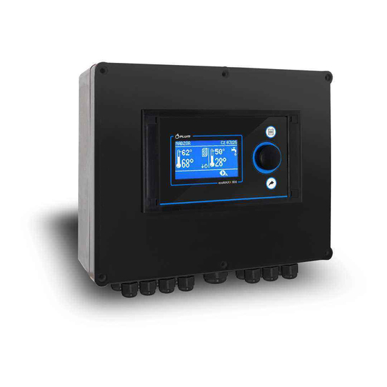
Burner Controller
ecoMAX850P1-A
FOR BOILERS FUELLED WITH PELLETS
* functions available in additional module B
** functions available in additional module MX.03
*** room panel ecoSTER200 (non standard option)
USER MANUAL FOR MAINTENANCE AND INSTALLATION
EDITION: 1.0
APPLIES FOR
HARDWARE:
MODULE A
MODULE B
v01.XX.XX
v.01.XX.XX
2013-07-22
PANEL
v.01.XX.XX
Advertisement
Table of Contents

Related Manuals for Plum ecoMAX850P1-A


Summary of Contents for Plum ecoMAX850P1-A
- Page 1 Burner Controller ecoMAX850P1-A FOR BOILERS FUELLED WITH PELLETS * functions available in additional module B ** functions available in additional module MX.03 *** room panel ecoSTER200 (non standard option) USER MANUAL FOR MAINTENANCE AND INSTALLATION EDITION: 1.0 APPLIES FOR MODULE A...
-
Page 3: Table Of Contents
INDEX SAFETY PRECAUTIONS ......... 5 12.7 TEMPERATURE SENSORS CONNECTION ..27 12.8 WEATHER SENSORS CONNECTION ....27 GENERAL INFORMATION ........6 12.9 WEATHER SENSORS CHECKING ..... 27 DATA REFERRING TO DOCUMENTATION .... 6 12.10 OPTICAL SENSOR CONNECTION ..... 28 DOCUMENTATION STORAGE ......6 12.11 MIXERS ROOM TEMPERATURE CONNECTION SYMBOLS AND MARKINGS USED ...... -
Page 5: Safety Precautions
The controller must be installed by the SAFETY PRECAUTIONS boiler producer, in accordance with valid norms and regulations Safety requirements are described in Modification programmed following sections this user’s parameters should only be carried by manual. Apart from them please obey a person acquainted with this user’s requirements described... -
Page 6: General Information
We do not take responsibility for damages GENERAL INFORMATION caused by failing to observe the following user manual. The controller is a modern electronic device DOCUMENTATION STORAGE designed to handling the work of the pellet boiler using help of optical flame brightness We advise you to keep carefully this user sensor. - Page 7 USER MANUAL OF THE CONTROLLER ecoMAX850P-A...
-
Page 8: User Menu Structure
HUW cont. hysteresis USER MENU STRUCTURE HUW disinfection Automatic disinfection SUMMER* Activ. temperature SUMMER* Main menu Deactv. temperature SUMMER* Information Boiler settings Mixer settings 1,2,3,4,5 HUW settings* Preset mixer temperature Mixer 1 settings* Mixer room thermostat Mixer 2 settings * Weather control mixer * Heating curve Mixer* Mixer 3 settings *... -
Page 9: Controller Maintenance
CONTROLLER MAINTENANCE 1. Controller’s working modes: FIRE UP, OPERATION, SUPERVISION, BURNING this chapter shortened controller’s OFF, BURNING OFF ON DEMAND, STOP, handling is described. 2. Boiler preset temperature, BUTTONS DESCRIPTION 3. Boiler measured temperature, 4. Functions having influence on preset boiler temperaturę. -
Page 10: Controller Start Up
17. Additional feeder (connected to module BOILER TEMPERATURE Right window main screen SETTING configurable, allows on changing information The preset boiler temperature and preset displayed there.It is possible to choose a circuits temperature can be set in the menu conficuration displaying: mixer circuit (1, 2, (Possible temperatures are restricted with 3, 4, 5), info or HW by twisting the “TOUCH range of respective service parameters of the... -
Page 11: Work
There are three power levels: WORK Maximal power 100% Medium power 50% Minimum power 30% Current power level is displayed on the screen as 3 segmented indicato rat the left side of boiler’s icon. Pic. 5 Main window view while operating. The fan operates constantly –... -
Page 12: Supervision
Parameters of SUPERVISION mode are to be Operation in Fuzzy Logic mode set in accordance to burner/boiler producer’s recommendations. They should be so chosen Fuzzy Logic mode controller to prevent the furnace from burning off automatically regulates burner power during boiler’s pauses (the furnace should allow boiler operation in such a way to not at the same fire up to too high a maintain its temperature on preset level. -
Page 13: Grid
By boiler operation configuration with the buffer decrease of top buffer temperature Setting HW priority, by parameter below preset value (Temperature when Priority – then pump start buffer feeding). deactivated to feed the HW boiler quicker, 8.10 GRID ... -
Page 14: Hot Water Feeder Disinfection
8.15 HOT WATER FEEDER DISINFECTION Mixer with weather sensor setting The controller can automatically, periodically (without room panel ecoSTER200) make HW silo warm up to 70 degrees C. It is parameter mixer weather control in position done to remove bacterial flora. on. -
Page 15: Weather Control
this configuration room thermostat ecoSTER is able to: Attention: in the proces of experimental reduce temperature of heating cycle by a adjustement of proper heating curve it is constant value, when preset temperature in necessary exlude influence room a room will be reached. Similarly like it was thermostat on controller work (irrespectively described previous... -
Page 16: Night Decrease Settings Description
If by frosty weather room temperature is too low and in warmer time too high – it is recommended to reduce parameter heating curve parallel shift and choose higher heating curve. Buildings which are poorly isolated require setting heating curve with higher values, and for better isolated buildings heating curve will have lower value. -
Page 17: Circular Pump Control
Pic. 13 Signalling time periods. Pic. 14 Auxiliary window with fuel level display. Fuel level indicator service Each time when fuel silo is filled to required 8.19 CIRCULAR PUMP CONTROL level it is necessary to press and keep the Attention: functionality of circular pump is knob in main window. -
Page 18: Cooperation With Additional Feeder
Menu – Boiler settings – Fuel level – fuel 8.23 MANUAL CONTROL level calibration – fuel level 100% In the controller it is possible to manualy In main window the indicator will be set on activate devices like i.e. pumps, feeder 100%. - Page 19 USER MANUAL CONTROLLER INSTALLATION SERVICE SETTINGS ecoMAX850P-A...
-
Page 20: Hydraulic Schemes
HYDRAULIC SCHEMES 9.1 SCHEME 1 Scheme with 4 way steering valve controlling central heating circuit , where: 1 – boiler, 2 – Pic. 17 burner, 3 – controller, 4 – boiler temperature sensor, CT4, 5 – fumes temperature sensor, 6 – servomotor of 4 way valve, 7 –... -
Page 21: Scheme 2
9.2 SCHEME 2 Scheme with heating buffer , where:1 – boiler, 2 – burner, 3 – controller, 4 – boiler temperature Pic. 18 sensor, 5 – fumes temperature sensor, 6 – boiler pump, 7 – heating buffer, 8 – hot water pump, 9 – hot water silo, 10 –... -
Page 22: Scheme 3
9.3 SCHEME 3 Scheme with heating buffer and 5 mixing heating circuits , where: 1 – boiler, 2 – burner, 3 – Pic. 19 controller, 4 – boiler temperature sensor CT4, 5 – fumes temperature sensor CT2S, 6 – boiler pump, 7 – heating buffer, 8 –... -
Page 23: Technical Data
STORAGE TRANSPORT TECHNICAL DATA CONDITIONS Power 230V~; 50Hz; controller exposed immediate effects of atmospheric conditions Current consumed by controller I = 0,04 A i.e. rain or sunrays. Temperature of storage and transport should be within scope -15…65 Maximum nominal current 6 (6) A degrees C. -
Page 24: Installation
12.3 INSTALLATION The controller is adapted to be installed on flat assembly surface. In order to screw it to assemble surface please undo the screws (3) and carefuly lift the cover (1), then undo the plug (4). Then remove the cover (1) in a safe place. Using screws (5) stuck through holes in the cover (2) screw the controller to assembly surface (6). - Page 25 Connecting wires should not touch with surfaces with temperatures exceeding nominal temperaturę of their work. Claps on the right side of the device are marked as L, N, 1-19 are designed to connect devises powered with current 230V~. Claps 20-40, D+, D- and RJ are designed to cooperate with low voltage devices (below 12V).. Connecting current 230V to claps 20 –...
-
Page 26: Safety Connections
12.5 SAFETY CONNECTIONS Safety wires are to be connected with terminals marked with this symbol 12.6 ELECTRIC SCHEME Pic. 22 Scheme of electrical connections of the controller, where: T1 – boiler temperature sensor CT4, T2 – hot water temperature sensor CT4, T3 – feeder temperature sensor, OS – flame optical sensor, AL/RB – currency exit to alarm signal or steering the auxiliary silo, RELAY –... -
Page 27: Temperature Sensors Connection
To connect use wire with diameter at least 12.7 TEMPERATURE SENSORS 0,5mm2 up to 25m long. Polarization of CONNECTION wires is not essential. Second end should be Wires of the sensors can be extended by connected terminals controller wires with diameter smaller than... -
Page 28: Optical Sensor Connection
12.12 BOILER ROOM THERMOSTAT CONNECTION CT2S-2 fumes Room thermostat for boiler circuit can switch Temp. Min. Nom. Max. °C Ω Ω Ω off the burner operation or switch off the CH 999,7 1000,0 1000,3 boiler pump. In order to thermostat switch 1096,9 1097,3 1097,7... - Page 29 Switching controller into controller equipped with STAND-BY mode causes transmitter as standard option. deactivating the additional boiler. Assembly of transmitter should be done by a person with proper qualifications. According to valid norms and regulations. To activate control over additional boiler set the parameter Reserve boiler deactivation temperature...
-
Page 30: Alarms Signal Connection
Pic. 28 External alarm device connection, where: 1 – controller, 2- external alarm device, 3- transmitter Then in order to operate correctly set proper code for active alarms signal in menu: Menu Service settings Boiler → → settings → Alarms Choosing value „127”... -
Page 31: Mixer Connection
If any of alarms is to be reported AL2, AL3 – Connect electrical power to mixer set parameter for “6” servomotor with controller, according to point 12.4 and value 12.15 MIXER CONNECTION servomotor producer’s documentation. confuse During assembly works for mixer opening direction with... -
Page 32: Temperature Limiter Connection
12.17 TEMPERATURE LIMITER Room thermostat (controls up to 3 CONNECTION thermostats) Controlling panel for the boiler In order not to overheat the boiler due to the Alarm signal controller breakdown it is obligatory to use Fuel level indicator STB safety temperature limiter or any other 4 way connection: one suitable for given boiler. -
Page 33: Structure – Service Menu
Grate* STRUCTURE – SERVICE MENU Flush time SUPERVISION Flush period SUPERVISION Min. airflow output Service settings Fuel detection time Burner settings Max. burner temperature Boiler settings Additional feeder operation time CH and HUW settings Buffer settings* Boiler settings Mixer 1 settings * Thermostat selection Mixer 2 settings *... -
Page 34: Service Settings
SERVICE SETTINGS 14.1 BURNER SERVICE SETTINGS Burner settings Firing up Description Ignition test time Time for checking if furnace is hot. Only fan is operating Time for feeding fuel when firing up. It refers to the first attempt. In next ... -
Page 35: Boiler Service Settings
Flame brightness with which airflow starts when burning off the fuel in Air flush stop burning off process Cleaning Poker p. before inflame Fan operation time during cleaning the furnace while firing up Poker p. after bur.off Fan operation time during furnace burning off ... -
Page 36: Ch And Hw Service Settings
Group of parameters available after connecting return sensor, responsible for protection of boiler return in hydraulic installation with 4 way valve equipped in mixer servomotor, point 9.1. It is not advised to activate functions of return protection because it may cause frequent Return protection* stops in power of mixer cycle. -
Page 37: Buffer Service Settings
Parameter determines how high the boiler temperature will be increased to load HW silo, buffer and mixer cycle. Temperature increase is only realizing when it is necessary. When preset boiler temperature is at Boiler Increase byHUW and Mixer sufficient level then controller will not change it due to the fact of feeding the HW silo, buffer or mixer cycle. -
Page 38: Advanced Parameters
When mixer cycle temperaturę exceeds value set in parameter mixer preset temperaturę, feeding of mixer pump is stopped. After decreasing temperature of circuit by 2 degrees C – pump is reactivated. This option is normally used to control floor heating pump ... -
Page 39: Default Settings Restoring
DEFAULT SETTINGS RESTORING Default settings restore Restoring service settings settings from main menu are restored. -
Page 40: Alarms Descriptions
If the feeder temperature increases above ALARMS DESCRIPTIONS this value the controller will begin burning off procedure. 16.1 BOILER MAX. TEMP. EXCEEDING Alarm is deleted automatically after feeder Protection against boiler overheating is done temperature decrease by 10C. in 2 steps. In the first step , after exceeding Boiler cooling off temperature, the controller Function... -
Page 41: Communication Loss
Deleting is done by pressing TOUCH and PLAY button or by deactivating and activating 16.6 FIRING UP FAILED ATTEMPT electrical power to the controller. Alarm will appear after third failed attempt of It is necessary to check the sensor and automatic furnace firing up. -
Page 42: Network Fuse Replacement
Boiler settings 17.4 NETWORK FUSE REPLACEMENT Output modulation Circuit fuse positioned inside 100% Blow-in output 100% Feeder operation controller’s cover. The fuse can only be 100% Oxygene replaced person holding proper 50% H2 Hysteresis qualifications after disconnecting ... -
Page 43: Possible Faults Description
POSSIBLE FAULTS DESCRIPTION Symptoms Tips 1. There are no signs of Check: operation device If line fuses are not blown, replace if necessary despite connection If the wire connecting panel with the executive module is plugged the network. correctly and if module is not damaged. -
Page 44: Producer
Default settings for given boilers / burners should be consultet with Company Plum Sp. z o.o.. In order to load new parameters go to Menu – service settings – special password and choose proper boiler/burner. Default settings can also be loaded by special software provided by Company Plum Sp. - Page 48 Ignatki 27a, 16-001 Kleosin Poland tel. +48 85 749-70-00 fax +48 85 749-70-14 plum@plum.pl www.pum.pl www.plumelectronics.eu...
Need help?
Do you have a question about the ecoMAX850P1-A and is the answer not in the manual?
Questions and answers