Table of Contents
Advertisement
Quick Links
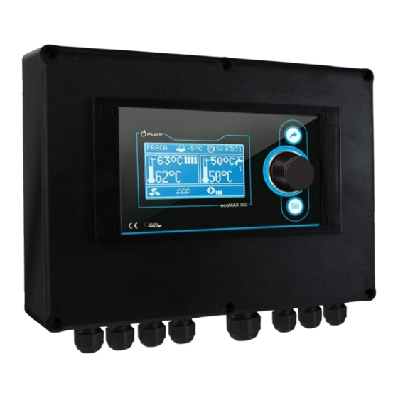
Burner Controller
ecoMAX850P1-R
FOR BOILERS FUELLED WITH PELLETS
* functions available in additional module B
** functions available in additional module C-MX.03
*** room panel ecoSTER200 (non standard option)
USER MANUAL FOR MAINTENANCE AND INSTALLATION
EDITION: 1.0
APPLIES FOR
HARDWARE:
MODULE A
MODULE B
v01.XX.XX
v.01.XX.XX
2013-09-11
PANEL
v.01.XX.XX
Advertisement
Table of Contents

Related Manuals for Plum ecoMAX850P1-R


Summary of Contents for Plum ecoMAX850P1-R
- Page 1 Burner Controller ecoMAX850P1-R FOR BOILERS FUELLED WITH PELLETS * functions available in additional module B ** functions available in additional module C-MX.03 *** room panel ecoSTER200 (non standard option) USER MANUAL FOR MAINTENANCE AND INSTALLATION EDITION: 1.0 APPLIES FOR MODULE A...
- Page 3 INDEX SAFETY PRECAUTIONS ........5 12.14 ALARMS SIGNAL CONNECTION ...... 31 GENERAL INFORMATION ....... 6 12.15 MIXER CONNECTION ........32 DATA REFERRING TO DOCUMENTATION ..6 12.16 TEMPERATURE LIMITER CONNECTION STB ... 32 DOCUMENTATION STORAGE ......6 12.17 ROOM PANEL CONNECTION ......33 SYMBOLS AND MARKINGS USED ....
-
Page 5: Safety Precautions
The controller must be installed by the SAFETY PRECAUTIONS boiler producer, in accordance with valid norms and regulations. Safety requirements are described in Modification programmed following sections this user’s parameters should only be carried by manual. Apart from them please obey a person acquainted with this user’s requirements described... -
Page 6: General Information
We do not take responsibility for damages GENERAL INFORMATION caused by failing to observe the following The controller is a modern electronic device user manual. designed to handling the work of the pellet DOCUMENTATION STORAGE boiler using help of optical flame brightness sensor. - Page 7 USER MANUAL OF THE CONTROLLER ecoMAX850P1-R...
-
Page 8: User Menu Structure
Room temperaturę factor* USER MENU STRUCTURE Night time decrease Boiler Main menu Mixer 1* Information Mixer 2* Boiler settings Mixer 3* HUW settings* Mixer 4* Mixer 1 settings* Mixer 5* Mixer 2 settings * HUW container* Circulation pump* Mixer 3 settings * Mixer 4 settings * Mixer 5 settings * General settings... -
Page 9: Controller Maintenance
CONTROLLER MAINTENANCE this chapter shortened controller’s 1. Controller’s working modes: FIRE UP, handling is described. OPERATION, PAUSE, SUPERVISION, STOP. BUTTONS DESCRIPTION 2. Boiler preset temperature, 3. Boiler measured temperature, 4. Functions having influence on preset boiler temperaturę. Following symbols signal respectively: ,,T”... -
Page 10: Controller Start Up
Right window main screen BOILER TEMPERATURE SETTING configurable, allows on changing information The preset boiler temperature and preset displayed there.It is possible to choose a circuits temperature can be set in the menu conficuration displaying: mixer circuit (1, 2, (Possible temperatures are restricted with 3, 4, 5), info or HW by twisting the “TOUCH range of respective service parameters of the and PLAY”... - Page 11 After finding and solving the cause of firing up failure the boiler should be fired up again. WORK The fan operates constantly – see Pic. 5. Fuel feeder is engaged periodically. One period consists of feeder operating time and pause in feeding time.
- Page 12 there is no need to restart the boiler boiler controller will go in STOP mode. SUPERVISION For setting Supervision time = 0 the SUPERVISION mode is applicable either in controller omits SUPERVISION mode regulation in STANDARD and Fuzzy Logic and goes directly to STOP. mode.
-
Page 13: Hot Water Temperature Settings
8.11 HOT WATER TEMPERATURE SETTINGS 8.14 HOT WATER FEEDER Preset temperature defined DISINFECTION parameter: The controller can automatically, periodically Menu → HUW settings → Preset HUW make HW silo warm up to 70 degrees C. It is temperature done to remove bacterial flora. 8.12 HYSTERESIS OF HOT WATER It is absolutely important to inform... -
Page 14: Weather Control
When this value is reduced correctly then this configuration room thermostat room temperature increase will be stopped. ecoSTER is able to: reduce temperature of heating cycle by a Mixer with weather sensor setting constant value, when preset temperature in (without room panel ecoSTER200) -
Page 15: Night Decrease Settings Description
if room thermostat is connected or not), by adjusting parameter: frosty weather room For mixer cycle: Mixer settings 1 – temperature is too low and in warmer time Mixer room thermostrat too high – it is recommended to reduce case connected room... -
Page 16: Circular Pump Control
Pic. 11 Signalling time periods. 8.18 CIRCULAR PUMP CONTROL Settings are in: MENU → Night time decrease →Circular pump. Menu → Service settings → CH and HUW settings Pic. 9 Time periods edition. Settings of time control of circular pump are Below sample preset... -
Page 17: Cooperation With Additional Feeder
Fuel level indicator service 8.20 COOPERATION WITH Each time when fuel silo is filled to required ADDITIONAL FEEDER level it is necessary to press and keep the After connecting additional B module the knob in main window. Following info will controller can cooperate with low fuel level appear: sensor in silo. - Page 19 USER MANUAL CONTROLLER INSTALLATION SERVICE SETTINGS ecoMAX850P1-R...
-
Page 20: Hydraulic Schemes
HYDRAULIC SCHEMES 9.1 SCHEME 1 Scheme with 4 way steering valve controlling central heating circuit , where: 1 – boiler, 2 – Pic. 14 burner, 3 – controller, 4 – boiler temperature sensor, CT4, 5 – fumes temperature sensor, 6 – servomotor of 4 way valve, 7 –... - Page 21 9.2 SCHEME 2 Pic. 15 Scheme with heating buffer , where:1 – boiler, 2 – burner, 3 – controller, 4 – boiler temperature sensor, 5 – fumes temperature sensor, 6 – boiler pump, 7 – heating buffer, 8 – hot water pump, 9 – hot water silo, 10 –...
- Page 22 9.3 SCHEME 3 Pic. 16 Scheme with heating buffer and 5 mixing heating circuits , where: 1 – boiler, 2 – burner, 3 – controller, 4 – boiler temperature sensor CT4, 5 – fumes temperature sensor CT2S, 6 – boiler pump, 7 – heating buffer, 8 –...
-
Page 23: Technical Data
Level of contamination TECHNICAL DATA wg PN-EN 60730-1 Power 230V~; 50Hz; STORAGE TRANSPORT Current consumed by controller I = 0,04 A CONDITIONS Maximum nominal current 6 (6) A controller exposed Controller’s level of protection IP20 immediate effects of atmospheric conditions i.e. -
Page 24: Installation
12.3 INSTALLATION The controller is adapted to be installed on flat assembly surface. In order to screw it to assemble surface please undo the screws (3) and carefuly lift the cover (1), then undo the plug (4). Then remove the cover (1) in a safe place. Using screws (5) stuck through holes in the cover (2) screw the controller to assembly surface (6). - Page 25 Claps 20-40, D+, D- and RJ are designed to cooperate with low voltage devices (below 12V).. Connecting current 230V to claps 20–40 and transmission connections causes damage to the controller and brings danger of electrical shock! Pic. 18 Wire connection, where 1 – correctly connected wire, 2 – incorrectly connected wire (it is not acceptable to twist wires inside the device) Wires inside the controller should be led through cable glands.
-
Page 26: Safety Connections
12.5 SAFETY CONNECTIONS Safety wires are to be connected with terminals marked with this symbol 12.6 ELECTRIC SCHEME Pic. 19 Scheme of electrical connections of the controller, where: T1 – boiler temperature sensor CT4, T2 – hot water temperature sensor CT4, TB – boiler room thermostat, OS – flame optical sensor, AL/RB – currency exit to alarm signal or steering the auxiliary silo, RELAY –... - Page 27 Figure 20 Wiring diagram - Modules B and C, where: T1 - temperature sensor for mixing valve 2 or 4 CT4, T2 - temperature sensor for mixing valve 3 or 5 CT4, T3 - upper buffer temperature sensor , T4 - lower buffer sensor CT4, T - room thermostat, B - extension module C - extension module, 230V - power cord, PM - mixing valve pump, SM - mixing valve actuator,...
-
Page 28: Temperature Sensors Connection
according to Pic. 19 or properly to used kind 12.7 TEMPERATURE SENSORS of controller. CONNECTION The sensor should be screw to the wall. Wires of the sensors can be extended by Acces to assembly holes is possible after wires with diameter smaller than... -
Page 29: Boiler Room Thermostat Connection
CT2S-2 fumes 12.12 BOILER ROOM THERMOSTAT Temp. Min. Nom. Max. CONNECTION °C Ω Ω Ω Room thermostat for boiler circuit can switch 999,7 1000,0 1000,3 off the burner operation or switch off the CH 1096,9 1097,3 1097,7 1193,4 1194,0 1194,6 boiler pump. - Page 30 Switching controller into The controller is not equipped with STAND-BY mode causes transmitter as standard option. deactivating the additional boiler. Assembly of transmitter should be done by a person with proper qualifications. According to valid norms and regulations. To activate control over additional boiler set the parameter Reserve boiler deactivation temperature...
-
Page 31: Alarms Signal Connection
Pic. 25 External alarm device connection, where: 1 – controller, 2- external alarm device, 3- transmitter Then in order to operate correctly set proper code for active alarms signal in menu: Menu Service settings Boiler → → settings → Alarms Choosing value „127”... -
Page 32: Mixer Connection
If any of alarms is to be reported AL2, AL3 – Do not confuse opening direction with set parameter for “6” closing direction, Connect electrical power 12.15 MIXER CONNECTION controller and switch it into STAND-BY mode During assembly works for mixer Check if wires for mixer opening and servomotor pay attention not to closing are not swapped. -
Page 33: Room Panel Connection
Safety temperaturę limiter must Alarm signal have nominal voltage at least Fuel level indicator 230V should have valid 4 way connection: admission documents Connect accordingly to point. 12.6 In case of not installing the limiter terminals 2 way connection: 1-2 are to be connected by a bridge. The 2 wire connection requires usage of power bridge must be made with insulated wire, supply feeder 5V of direct current with... -
Page 34: Structure - Service Menu
Clamps 28-29 delay STRUCTURE – SERVICE MENU Boiler settings Thermostat selection Service settings Min.boiler temperature Burner settings Max. Boiler temperature Boiler settings Reserve boiler CH and HUW settings Alarms Buffer settings* Boiler cooling temperature Mixer 1 settings * Pump off by thermostat Mixer 2 settings * Mixwer 3 settings * CH and HUW settings... - Page 35 13.1 BURNER SERVICE SETTINGS Burner settings Firing up Description Ignition test time Time for checking if furnace is hot. Only fan is operating Time for feeding fuel when firing up. It refers to the first attempt. In next Feeding time attempts the amount of fuel is smaller (20% of basic amount) Threshold of flame detection in % of light, when the controller deems the ...
-
Page 36: Boiler Service Settings
algorithm of controlling the fan. It should be possibly small to allow the fan to rotate slowly, without buzzing. Time is measured after decrease in brightness of flame below value flame detection % . After deducting this time the controller switches into Fuel detection time firing up attempt. - Page 37 13.3 CH and HW SERVICE SETTINGS CH and HUW settings Parameters determines the temperature at which CH boiler pump is activated. It protects the boiler against watering due to cooling off with cold water returning from installation. Attention: Deactivating boiler pump CH activation temperature only does not guarantee boiler protection against watering and consequently corrosion.
-
Page 38: Buffer Service Settings
13.4 BUFFER SERVICE SETTINGS Buffer settings Parameter serves to activating buffer operating mode. Available after Activating operation connecting additional module B and buffer temperature sensors. Parameter buffer loading start temperature defines high temperature Loading start temperature below which buffer feeding starts. Buffer feeding proces is finished when low temperature reaches value defined in parameter buffer Loading end temp. -
Page 39: Default Settings Restoring
140s. Setting the parameter on YES value causes closing of mixer servomotor and deactivating mixer pump after disconnecting joints of Pump off by thermostat room thermostat. This is not recommended because the heated room can be too cool. Advanced parameter (hidden) available only if show hidden is set to (special... -
Page 40: Communication Loss
ALARMS DESCRIPTIONS 15.2 BOILER TEMP. SENSOR FAILURE Alarm appears by boiler sensor damage and 15.1 BOILER MAX. TEMP. EXCEEDING by exceeding measuring scope of this sensor. Protection against boiler overheating is done When alarm appears the boiler is activated. in 2 steps. In the first step , after exceeding Deleting is done by pressing TOUCH and Boiler cooling off temperature, the controller... -
Page 41: Firing Up Failed Attempt
15.4 FIRING UP FAILED ATTEMPT 16.4 NETWORK FUSE REPLACEMENT Alarm will appear after third failed attempt of Circuit fuse positioned inside automatic furnace firing up. In case of alarm controller’s cover. The fuse can only be all pumps are deactivated in order to not replaced person holding... - Page 42 Description of remaining parameters relaed to Lambda sond: Prameter Blow-in output scope sets permissible scope of variability of airflow power by work using lambda sond. Parameters Dynamics Reaction time have influence on regulation time of air amount in fumes to preset amount and on stability fumes.
-
Page 43: Possible Faults Description
POSSIBLE FAULTS DESCRIPTION Symptoms Tips 1. There are no signs of Check: operation device If line fuses are not blown, replace if necessary despite connection If the wire connecting panel with the executive module is plugged the network. correctly and if module is not damaged. -
Page 44: Changes Register
Default settings for given boilers / burners should be consultet with Company Plum Sp. z o.o. . In order to load new parameters go to Menu – service settings – special password and choose proper boiler/burner. Default settings can also be loaded by special software provided by Company Plum Sp. - Page 48 Ignatki 27a, 16-001 Kleosin Poland tel. +48 85 749-70-00 fax +48 85 749-70-14 plum@plum.pl www.pum.pl www.plumelectronics.eu...
Need help?
Do you have a question about the ecoMAX850P1-R and is the answer not in the manual?
Questions and answers