Table of Contents
Advertisement
Quick Links
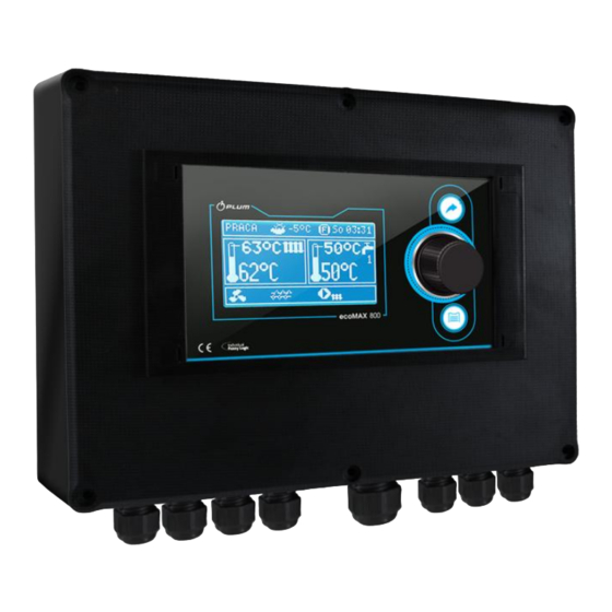
Burner Controller
ecoMAX850P1-V
FOR BOILERS FUELLED WITH PELLETS
* functions available in additional module B
** functions available in additional module C-MX.03
*** room panel ecoSTER200 (non standard option)
USER MANUAL FOR MAINTENANCE AND INSTALLATION
EDITION: 1.1
APPLIES FOR
HARDWARE:
MODULE A
MODULE B
v01.XX.XX
v.01.XX.XX
2013-06-11
PANEL
v.01.XX.XX
Advertisement
Table of Contents

Related Manuals for Plum ecoMAX850P1-V


Summary of Contents for Plum ecoMAX850P1-V
- Page 1 Burner Controller ecoMAX850P1-V FOR BOILERS FUELLED WITH PELLETS * functions available in additional module B ** functions available in additional module C-MX.03 *** room panel ecoSTER200 (non standard option) USER MANUAL FOR MAINTENANCE AND INSTALLATION EDITION: 1.1 APPLIES FOR MODULE A...
- Page 2 INDEX SAFETY PRECAUTIONS ........5 12.11 MIXERS ROOM TEMPERATURE CONNECTION ... GENERAL INFORMATION ....... 6 ............... 28 DATA REFERRING TO DOCUMENTATION ..6 12.12 BOILER ROOM THERMOSTAT CONNECTION .. 28 DOCUMENTATION STORAGE ......6 12.13 RESERVE BOILER CONNECTION ..... 28 SYMBOLS AND MARKINGS USED ....
-
Page 3: Safety Precautions
The controller must be installed by the SAFETY PRECAUTIONS boiler producer, in accordance with valid norms and regulations Safety requirements are described in Modification programmed following sections this user’s parameters should only be carried by manual. Apart from them please obey a person acquainted with this user’s requirements described... -
Page 4: General Information
We do not take responsibility for damages GENERAL INFORMATION caused by failing to observe the following The controller is a modern electronic device user manual. designed to handling the work of the pellet DOCUMENTATION STORAGE boiler using help of optical flame brightness sensor. - Page 5 USER MANUAL OF THE CONTROLLER ecoMAX850...
-
Page 6: User Menu Structure
Room temperaturę factor* USER MENU STRUCTURE Night time decrease Boiler Main menu Mixer 1* Information Mixer 2* Boiler settings Mixer 3* HUW settings* Mixer 4* Mixer 1 settings* Mixer 5* Mixer 2 settings * HUW container* Circulation pump* Mixer 3 settings * Mixer 4 settings * Mixer 5 settings * General settings... -
Page 7: Controller Maintenance
CONTROLLER MAINTENANCE this chapter shortened controller’s 1. Controller’s working modes: FIRE UP, handling is described. OPERATION, SUPERVISION, BURNING OFF, BURNING OFF ON DEMAND, STOP, BUTTONS DESCRIPTION 2. Boiler preset temperature, 3. Boiler measured temperature, 4. Functions having influence on preset boiler temperaturę. -
Page 8: Controller Start Up
16. Additional feeder (connected to module BOILER TEMPERATURE SETTING Right window main screen The preset boiler temperature and preset configurable, allows on changing information circuits temperature can be set in the menu displayed there.It is possible to choose a (Possible temperatures are restricted with conficuration displaying: mixer circuit (1, 2, range of respective service parameters of the 3, 4, 5), info or HW by twisting the “TOUCH... - Page 9 2. Fuzzy Logic – smooth output modulation WORK To set the regulation mode: Menu → Boiler settings → Regulation mode Standard mode operation Boiler output regulation begins when boiler temperature approaches preset temperature, i.e. when the boiler sensor reaches: Preset boiler temperature –...
-
Page 10: Hot Water Settings
Attention: boiler operates The parameters in this mode must without heat buffer and controller is be so chosen as to make the boiler switched into SUMMER mode than temperature gradually decreasing. Standard mode operation Incorrect settings can cause boiler controller is recommended. overheating. -
Page 11: Hot Water Temperature Settings
When the sensor is disconnected – the Function SUMMER activated information about it is displayed in the main automatically, on the basis of readings from window. By selecting: weather sensor. Use following parameters to Menu → HUW settings → HUW Pump activate this function: mode the user is able to:... -
Page 12: Weather Control
When this value is reduced correctly then room temperature increase will be stopped. this configuration room thermostat ecoSTER is able to: Mixer with weather sensor setting reduce temperature of heating cycle by a (without room panel ecoSTER200) constant value, when preset temperature in parameter mixer weather control in position... -
Page 13: Night Decrease Settings Description
Attention: in the proces of experimental adjustement of proper heating curve it is frosty weather room necessary exlude influence room temperature is too low and in warmer time thermostat on controller work (irrespectively too high – it is recommended to reduce if room thermostat is connected or not), by parameter heating curve parallel shift adjusting parameter:... -
Page 14: Circular Pump Control
Pic. 12 Signalling time periods. Pic. 10 Time periods edition. 8.18 CIRCULAR PUMP CONTROL Below sample preset night temperature Settings are in: reduction is presented. MENU → Night time decrease →Circular Attention, defining time periods pump. during one day must be started at oraz 00:00! Menu →... -
Page 15: Cooperation With Additional Feeder
8.20 COOPERATION WITH ADDITIONAL FEEDER Fuel level indicator service After connecting additional B module the Each time when fuel silo is filled to required controller can cooperate with low fuel level level it is necessary to press and keep the sensor in silo. - Page 16 8.23 Resetting STB limiter In emergency situations where the boiler is overheating, the STB temperature limiter may cut off the power supply to the feeder and fan. Reactivation requires resetting the limiter. Remove the nut (1) securing the reset button (2) and press the button. The nut is located in the top portion of the controller’s main housing.
- Page 17 USER MANUAL CONTROLLER INSTALLATION SERVICE SETTINGS ecoMAX850P...
-
Page 18: Hydraulic Schemes
HYDRAULIC SCHEMES 9.1 SCHEME 1 Scheme with 4 way steering valve controlling central heating circuit , where: 1 – boiler, 2 – Pic. 15 burner, 3 – controller, 4 – boiler temperature sensor, CT4, 5 – fumes temperature sensor, 6 – servomotor of 4 way valve, 7 –... - Page 19 9.2 SCHEME 2 Scheme with heating buffer , where:1 – boiler, 2 – burner, 3 – controller, 4 – boiler temperature Pic. 16 sensor, 5 – fumes temperature sensor, 6 – boiler pump, 7 – heating buffer, 8 – hot water pump, 9 – hot water silo, 10 –...
- Page 20 9.3 SCHEME 3 Scheme with heating buffer and 5 mixing heating circuits , where: 1 – boiler, 2 – burner, 3 – Pic. 17 controller, 4 – boiler temperature sensor CT4, 5 – fumes temperature sensor CT2S, 6 – boiler pump, 7 – heating buffer, 8 –...
-
Page 21: Technical Data
STORAGE TRANSPORT TECHNICAL DATA CONDITIONS Power 230V~; 50Hz; controller exposed immediate effects of atmospheric conditions Current consumed by controller I = 0,04 A i.e. rain or sunrays. Temperature of storage and transport should be within scope -15…65 Maximum nominal current 6 (6) A degrees C. -
Page 22: Installation
12.3 INSTALLATION The controller is adapted to be installed on flat assembly surface. In order to screw it to assemble surface please undo the screws (3) and carefuly lift the cover (1), then undo the plug (4). Then remove the cover (1) in a safe place. Using screws (5) stuck through holes in the cover (2) screw the controller to assembly surface (6). - Page 23 Connecting wires should not touch with surfaces with temperatures exceeding nominal temperaturę of their work. Claps on the right side of the device are marked as L, N, 1-19 are designed to connect devises powered with current 230V~. Claps 20-40, D+, D- and RJ are designed to cooperate with low voltage devices (below 12V).. Connecting current 230V to claps 20 –...
-
Page 24: Safety Connections
12.5 SAFETY CONNECTIONS Safety wires are to be connected with terminals marked with this symbol 12.6 ELECTRIC SCHEME Pic. 20 Scheme of electrical connections of the controller, where: T1 – boiler temperature sensor CT4, T2 – hot water temperature sensor CT4, T3 – feeder temperature sensor, OS – flame optical sensor, AL/RB – currency exit to alarm signal or steering the auxiliary silo, RELAY –... -
Page 25: Temperature Sensors Connection
wires is not essential. Second end should be 12.7 TEMPERATURE SENSORS connected terminals controller CONNECTION according to Pic. 20 or properly to used kind Wires of the sensors can be extended by of controller. wires with diameter smaller than The sensor should be screw to the wall. 0,5mm . -
Page 26: Optical Sensor Connection
CT2S-2 fumes 12.12 BOILER ROOM THERMOSTAT Temp. Min. Nom. Max. CONNECTION °C Ω Ω Ω Room thermostat for boiler circuit can switch 999,7 1000,0 1000,3 off the burner operation or switch off the CH 1096,9 1097,3 1097,7 1193,4 1194,0 1194,6 boiler pump. - Page 27 Switching controller into controller equipped with STAND-BY mode causes transmitter as standard option. deactivating the additional boiler. Assembly of transmitter should be done by a person with proper qualifications. According to valid norms and regulations. To activate control over additional boiler set the parameter Reserve boiler deactivation temperature...
-
Page 28: Alarms Signal Connection
Pic. 26 External alarm device connection, where: 1 – controller, 2- external alarm device, 3- transmitter Then in order to operate correctly set proper code for active alarms signal in menu: Menu Service settings Boiler → → settings → Alarms Choosing value „127”... -
Page 29: Mixer Connection
If any of alarms is to be reported AL2, AL3 – confuse opening direction with closing set parameter for “6” direction, Connect electrical power 12.15 MIXER CONNECTION controller and switch it into STAND-BY mode During assembly works for mixer Check if wires for mixer opening and servomotor pay attention not to closing are not swapped. -
Page 30: Room Panel Connection
Safety temperaturę limiter must 4 way connection: have nominal voltage at least Connect accordingly to point. 12.6 230V should have valid admission documents 2 way connection: 2 wire connection requires usage of power In case of not installing the limiter terminals supply feeder 5V of direct current with 1-2 are to be connected by a bridge. -
Page 31: Structure - Service Menu
Blow-in output STRUCTURE – SERVICE MENU Min. airflow output Fuel detection time Max. burner temperature Service settings Additional feeder operation time Burner settings Boiler settings Boiler settings CH and HUW settings Thermostat selection Buffer settings* Return protection* Mixer 1 settings * Min.boiler temperature Mixer 2 settings * Max. - Page 32 BURNER SERVICE SETTINGS Burner settings Firing up Description Ignition test time Time for checking if furnace is hot. Only fan is operating Time for feeding fuel when firing up. It refers to the first attempt. In next Feeding time attempts the amount of fuel is smaller (20% of basic amount) Threshold of flame detection in % of light, when the controller deems the ...
-
Page 33: Boiler Service Settings
Supervision After this time, when the controller is in SUPERVISION mode, the Supervision time controller automatically starts burner burning off. By settings = 0, SUPERVISION mode is deactivated. Fuel feeding in SUPERVISION mode. It has influence on burner power by operating in SUPERVISION mode. - Page 34 Temperature of boiler cooling off. Above this temperaturę the controller activates HW pump and opens mixer cycles to allow boiler cooling off. Boiler cooling temperature The controller activates HW pump if this temperature exceeds maximum value. The controller will not open mixer cycle when mixer setting floor active...
-
Page 35: Buffer Service Settings
Parameter determines how high the boiler temperature will be increased to load HW silo, buffer and mixer cycle. Temperature increase is only realizing when it is necessary. When preset boiler temperature is at Boiler Increase byHUW and Mixer sufficient level then controller will not change it due to the fact of feeding the HW silo, buffer or mixer cycle. -
Page 36: Default Settings Restoring
When mixer cycle temperaturę exceeds value set in parameter mixer preset temperaturę, feeding of mixer pump is stopped. After decreasing temperature of circuit by 2 degrees C – pump is reactivated. This option is normally used to control floor heating pump ... -
Page 37: Communication Loss
ALARMS DESCRIPTIONS The controller can not be used as sole protection of boiler against 16.1 BOILER MAX. TEMP. EXCEEDING back fire. Additional protecting Protection against boiler overheating is done automatics is to be used or ensure in 2 steps. In the first step , after exceeding a secure boiler/burner design.. -
Page 38: Firing Up Failed Attempt
16.5 FIRING UP FAILED ATTEMPT 17.4 NETWORK FUSE REPLACEMENT Alarm will appear after third failed attempt of Circuit fuse positioned inside automatic furnace firing up. In case of alarm controller’s cover. The fuse can only be all pumps are deactivated in order to not replaced person holding... - Page 39 Description of remaining parameters relaed to Lambda sond: Prameter Blow-in output scope sets permissible scope of variability of airflow power by work using lambda sond. Parameters Dynamics Reaction time have influence on regulation time of air amount in fumes to preset amount and on stability fumes.
-
Page 40: Possible Faults Description
POSSIBLE FAULTS DESCRIPTION Symptoms Tips 1. There are no signs of Check: operation device If line fuses are not blown, replace if necessary despite connection If the wire connecting panel with the executive module is plugged the network. correctly and if module is not damaged. -
Page 41: Changes Register
Default settings for given boilers / burners should be consultet with Company Plum Sp. z o.o. . In order to load new parameters go to Menu – service settings – special password and choose proper boiler/burner. Default settings can also be loaded by special software provided by Company Plum Sp. - Page 42 Контакты: Адрес: г. Москва ул. Родниковая д. 7 (Станция метро Юго-Западная) Телефон: +7 964 556 4411, +7 905 579 6633 Телефон сервис центра: 8 963 695 44 11 E-mail: 5564411@mail.ru, 5564411@ooo-bioterm.ru...
Need help?
Do you have a question about the ecoMAX850P1-V and is the answer not in the manual?
Questions and answers