Table of Contents
Advertisement
REGULATOR
ecoMAX860P3-LZ
FOR PELLET BOILERS
ecoSTER TOUCH*
ecoSTER200*
ecoNET300*
ecoNET.apk
ecoNET.app
www.econet24.com
* room panel ecoSTER TOUCH or ecoSTER200 and ecoNET300 internet module isn't
the standard equipment of the regulator.
SERVICE AND ASSEMBLY MANUAL
ISSUE: 1.1_EN
functions
additional module B
10-2018
available
in
the
Advertisement
Table of Contents

Subscribe to Our Youtube Channel
Related Manuals for Plum ecoMAX860P3-LZ


Summary of Contents for Plum ecoMAX860P3-LZ
- Page 1 REGULATOR ecoMAX860P3-LZ FOR PELLET BOILERS ecoSTER TOUCH* ecoSTER200* ecoNET300* ecoNET.apk ecoNET.app www.econet24.com functions available additional module B * room panel ecoSTER TOUCH or ecoSTER200 and ecoNET300 internet module isn’t the standard equipment of the regulator. SERVICE AND ASSEMBLY MANUAL ISSUE: 1.1_EN...
- Page 2 ELECTRIC DEVICE UNDER VOLTAGE! Before any action related to the power supply (cables connection, device installation etc.) check if the regulator is not connected to the mains! Installation should be done by a person with appropriate electrical qualifications. Improper cables connection could result in the regulator damage.
-
Page 3: Table Of Contents
TABLE OF CONTENTS RECOMMENDATIONS REGARDING SAFETY ..4 12.10 ....26 ONNECTION OF WEATHER SENSOR GENERAL INFORMATION ........5 12.11 ......26 ONNECTING EXHAUST SENSOR INFORMATION ABOUT DOCUMENTATION ..5 12.12 ....27 HECKING OF TEMPERATURE SENSORS STORAGE OF DOCUMENTATION ......5 12.13 .. -
Page 4: Recommendations Regarding Safety
The regulator is not an intrinsically Recommendations regarding safe device, which means that in the safety case of malfunction it can be the Requirements concerning safety source spark high described in detail in individual chapters of temperature, which in the presence of this manual. -
Page 5: General Information
Applied symbols General information In this manual the following graphic symbols The regulator ecoMAX860P3-LZ is intended are used: control pellet boiler operation. regulator it automatically maintains a preset - useful information and tips, boiler temperature by controlling the fuel - important information, failure to... -
Page 7: Instruction Manual
INSTRUCTION MANUAL ecoMAX860P3-LZ... -
Page 8: User Menu - Structure
User menu - structure Mixer 1-4 settings* Preset mixer temp. Main menu Mixer room therm. Information Mixer out.temp.dep Boiler settings Mixer heating curve HUW settings Curve shift Summer/Winter Room temp.factor Mixer 1-4 settings* Night time decrease Night time decrease Work acc. schedule** Boiler: General settings Night time decrease, Schedule... -
Page 9: Operating The Regulator
,,T” Preset boiler temperature decrease Operating the regulator due to thermostat disconnection. This section briefly describes ,,S” Preset boiler temperature decrease regulator should be operated. due to activated time intervals. ,,C” Boiler preset temperature during Description of panel operation loading the hot water (HUW). The regulator is operated by touch buttons ,,M”... -
Page 10: Setting Preset Boiler Temperature
Conditions of the furnace are checked – i.e. once the exhaust temperature has reached the value of Ex. temp. at the end of firing- or has increased by Ex. temp. delta within the time set in the parameter Ignition test time elapsed from the fan start, firing-up process stops. -
Page 11: Operation Mode
aimed at stabilizing the combustion process before switching to the OPERATION mode. The duration of the mode is set in the parameter Stabilization time. OPERATION mode OPERATION mode operates continuously, fuel feeder switches periodically. The operation cycle is composed of feeder operation time and feeder standstill time. -
Page 12: Burning Off Mode
Airflow in the SUPERVISION mode operates the boiler starts heating up to the preset with power set in the power modulation power in the parameter Preset power. The parameter 30% Airflow power. duration of the mode is set in the parameter The regulator returns to the OPERATION Working time. -
Page 13: Huw Container Disinfection
Function SUMMER activated error. room thermostat automatically, on the basis of readings from traditional thermostat (no/nc), or room panel weather sensor. Use following parameters to ecoSTER TOUCH. Upon activation of the activate this function: thermostat, preset mixer circuit Summer/Winter → SUMMER Mode → temperature will be decreased, which, if Auto proper decrease value is selected, will stop... -
Page 14: Weather Controlled Operation
specified previous point (not Guidelines for proper setting of the heating recommended), or curve: - automatically, continuously correct the floor heating 0,2 -0,6 heating cycle temperature. radiator heating 1,0 - 1,6 It is not recommended to use both options at ... -
Page 15: Circulating Pump Control
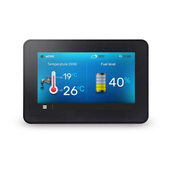
reduced automatically, without loss Tip: fuel level can also be seen in room panel heating comfort reducing fuel ecoSTER200 and ecoSTER TOUCH. consumption. Decrease of preset temperature in selected time intervals is indicated by the symbol “S” on the main screen. To activate time intervals, set the parameter Night time decrease for the given heating circuit to ON. -
Page 16: Information
point corresponding to minimal fuel level. Upon connection mixers' must systematically control extension module, information decreasing level of fuel in the bin. When the windows of additional mixers are level reaches the requested minimum, set displayed. the value of the parameter: Writing „CAL”... -
Page 17: Installation And Service Settings
INSTALLATION AND SERVICE SETTINGS ecoMAX860P3-LZ... -
Page 18: Hydraulic Diagrams
Hydraulic diagrams Diagram with a heat buffer , where: 1 – boiler, 2 – regulator, 3 – boiler temp. sensor, 4 – control panel, 5 – exhaust temp. sensor, 6 – boiler pump, 7 – buffer, 8 – HUW pump, 9 – HUW container, 10 – HUW temp. - Page 19 Diagram with thermostatic three-way valve which protects the temperature of return water where: 1 – boiler with feeder, 2 – regulator, 3 –control panel, 4 – boiler temp. sensor, 6 – boiler pump, 7 – thermostatic three-way valve, 8 – throttle (poppet) valve, 9 – room thermostate, 10 – weather temperature sensor, 11 –...
- Page 20 Diagram with thermostatic three-way valve which protects return water temperature, and two three-way valves which feed floor heating, as well as with two additional mixer cycles after connecting an extension module , where:1 – boiler, 2 – regulator, 3 – control panel, 4 – boiler temperature sensor, 6- boiler pump, 7 –...
-
Page 21: Technical Data
enviroment (eg coal). Regulator should be Technical data separated using appropriate enclosure. Power supply 230V~, 50Hz In addition, controller cannot be used in the Current consumed 0,04 A presence of water vapor condensation and be Maximum rated current 6 (6) A exposed to water. -
Page 22: Assembly Of Module
elements surrounding the whole module. Space required for mounting a working module is shown in below figures. Module housing does guarantee dust- waterproofness. To provide the required protection, appropriate module cover should be provided. The working module is designed to be mounted on a standard DIN TS35 rail. -
Page 23: Ip Rating
12.5 IP rating The housing of working module of the regulator provides various IP ratings, subject to the manner of assembly. Upon assembly carried out in accordance with this drawing, IP20 rating is provided at the front side of working module housing (this... -
Page 24: Electric Scheme
12.8 Electric scheme Diagram of electrical connection to the regulator: λ – Lambda module, B – module B to support additional 3 and 4 heat circuits, BH – upper buffer temp. sensor type CT4, BL – lower buffer temp. sensor type CT4, RPM –... - Page 25 Diagram of electrical connection to the B module: M3 – regulated circuit (mixer 3) sensor temperature type CT4, M4 - regulated circuit (mixer 4) sensor temperature type CT4, PL – fuel level sensor, T3 – mixer 3 room thermostat, T4 – mixer 4 room thermostat, H – voltage output for controlling: reserve boiler (R), alarm signaling (AL), HUW circulation pump (PC), RELAY –...
-
Page 26: Connection Of Temperature Sensors
Regulator works with weather sensors type 12.9 Connection of temperature CT6-P only. Fasten the weather sensor on sensors the coldest wall of the building - usually it is Regulator works with sensors - type CT4 and a roofed area of north wall. The sensor CT2S only. -
Page 27: Checking Of Temperature Sensors
CT6-P (weather) Temp. Min. Nom. Max. °C Ω Ω Ω 901,6 901,9 902,2 921,3 921,6 921,9 960,6 960,9 961,2 999,7 1000,0 1000,3 1096,9 1097,3 1097,7 1193,4 1194,0 1194,6 1384,2 1385,0 1385,8 1478,5 1479,4 1480,3 1572,0 1573,1 1574,2 CT2S-2 (exhaust) Temp. Min. -
Page 28: Connection Of Alarm Signalling
Example: connection of reserve boiler to regulator: 1- regulator, 2 – reserve boiler (gas- or oil-fired), 3 – RM 84-2012-35-1012 relay and GZT80 RELPOL base plate. Standard version of the regulator is not equipped with a relay. Reserve boiler control is switched off upon setting the Output H1 (Output H2) function to the Reserve boiler. -
Page 29: Connection Of Mixer Servo
which the temperature in mixer circuit is maximum and minimum (it corresponds to the setting of the regulator of "100% ON" "0% OFF, respectively). Note position to verify the connections later, - disconnect power supply to the regulator, - connect mixer servo and regulator wiring according valve servo... -
Page 30: Connection Of Room Panel
Acc. recent regulations, use of safety temperature limiters mandatory. 12.19 Connection of room panel Regulator may be equipped with ecoSTER200 and ecoSTER TOUCH room control panel, which may perform following functions: room thermostat, boiler control panel alarm annunciator, fuel level indicator. Cross-section area of wires used to connect ecoSTER200/ecoSTER TOUCH control panel should be of... -
Page 31: Service Menu - Structure
Airflow correction range Service menu - structure Feed lock Service settings Fuel detection - oxygen Boiler settings Fuel detection - time CH and HUW settings Buffer settings* CH and HUW settings Mixer 1-4 settings* CH activation temp. Output H CH standstill when load. HUW Show advenced setup Min. -
Page 32: Service Settings - Description
Service settings - description 14.1 Boiler Firing-up Airflow output durning the firing-up. Too high value slows the firing-up or causes Firing-up airflow unsuccessful attempt to fire up. Process of checking whether the furnace is already burning. Only the fan is ... -
Page 33: And Huw
Fuel detection - time Description in point 18 Parameter allows for room therm. select. for direct heating circuit.: OFF - turns off Thermostat selection thermostat operation, Universal - refers to stand. thermostat, ecoSTER 1,2,3 - thermostat signal is retrieved form ecoSTER TOUCH and ecoSTER200 panel. Min. -
Page 34: Buffer
when pump is deactivated. To cool off the boiler HUW pump operation can be prolonged by Extending HUW operation time. Pausing time between periods of circulation pump operation is defined with value Circulation standstill time of parameter Circulation standstill time (recommended setting 15-40 min.) Circular pump operates... -
Page 35: Other Parameters
Setting parameter determining value of temperature dead zone for mixer controlling circuit. The controller regulates mixer in such a way to keep the temperature of mixer cycle equal to preset value. However, avoid too frequent Mixer dead zone movements of servomotor, which can shorten its long-life usage. Regulation is undertaken only when measured temperature of mixer cycle will be higher or lower than preset value by the value bigger than Mixer dead zone. -
Page 36: Alarm Description
set time and the poker. The fan stops and ALARM DESCRIPTION the pumps start. Once the fuel has been "pushed out", the regulator stops the feeder 15.1 Exhaust temperature sensor and does not activate it again even though damage the feeder temperature remains high. This alarm occurs in case of damage of Alarm may be reset only upon drop of feeder exhaust temperature sensor and excess of its... -
Page 37: Feeder Control System Failure
boiler from flashback is disabled. 15.9 Unsuccessful boiler firing-up attempt This alarm produced after third 15.6 Feeder control system failure unsuccessful attempt of automatic furnace The regulator has an additional protection firing-up. Upon occurrence of this alarm, all preventing it from feeding fuel constantly. pumps stop to avoid excessive boiler cooling. -
Page 38: Replacement Of Parts And Components
purpose, these components are periodically the panel and of the working module is the (every 167h) switched on for a few seconds. same. In this way the pumps are protected from Software ID number may be taken immobilization caused by scale deposits. For from the rating plate of respective this reason,... - Page 39 automatically to obtain the set value of oxygen concentration in exhaust. If this parameter is set at Off - lambda sensor indications will have no effect on regulator operation. Desired values oxygen concentration are set in the menu: Service settings → Boiler settings → Output modulation Description of other parameters related to lambda sensor:...
-
Page 40: Troubleshooting
Troubleshooting Faults Hints Check: The display is blank despite if the main fuse is burnt-out, replace if so, connection to power supply. if the lead connecting the panel with the module is properly plugged in, and if it’s not damaged. Check: ... - Page 44 Wspólna 19, Ignatki 16-001 Kleosin Poland plum@plum.pl www.plum.pl...
Need help?
Do you have a question about the ecoMAX860P3-LZ and is the answer not in the manual?
Questions and answers