
Related Manuals for RHINO RMCS –2303


Summary of Contents for RHINO RMCS –2303
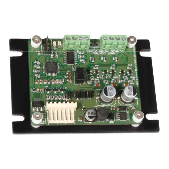
- Page 1 DC Servo Drive 10V - 30V DC, 50W with ASCII Modbus RMCS – 2303 Operating Manual v1.0 https://www.robokits.co.in/...
-
Page 2: Table Of Contents
Contents Introduction – Salient Features ......................3 Technical specifications and Pin description ..................4 Drive & Motor Connection ........................5 Modes of Operation ..........................6 Slave ID Addressing ...........................7 Basics of a servo drive ........................8 How to use the drive: ..........................9 Software Installation: ........................10 COM port Selection ........................ -
Page 3: Introduction - Salient Features
Introduction – Salient Features Rhino Motion Controls RMCS-2303 with UART ASCII is a high performance dc servo drive (10–30 V DC) designed for optimized operation of any DC Servo motors with quad encoder feedback. This is an amazing cost effective solution to provide closed loop servo control for various applications. -
Page 4: Technical Specifications And Pin Description
Technical specifications and Pin description Supply Voltage and Current Specification Units Comments Supply Voltage Volts DC Between +Ve and GND Phase Current Amps Peak 3 Amps per phase Pin description of the drive is as per below image: Pin No. Description Pin No. -
Page 5: Drive & Motor Connection
Drive & Motor Connection Motor Pin outs Drive Pin outs Motor Wire Color Pin No. Description Black VCC(5 V DC ) Brown +5VDC ENC_B(Encoder B) ENC_B/Hall W ENC_A(Encoder A) Orange ENC_A/Hall U M-( Motor-) Yellow Hall U M+( Motor+) Green Motor- / V Motor+ / U Power Supply Pin outs... -
Page 6: Modes Of Operation
The drive can be configured in the following three modes 1. Mode 0: Analog speed control mode: In this mode the speed of the Rhino DC Servo motor can be controlled by an externally connected Potentiometer. Speed can be increased or decreased manually based on requirement using potentiometer. -
Page 7: Slave Id Addressing
Slave ID Addressing Multiple drives with different slave addresses can be used with a single controller on single UART bus. For this all drives should have a unique Slave Address. Using the GUI software or Modbus commands, the slave ID can be set from 1 to 247. However, slave ID from 1 to 7 can be set using physical jumpers also. As shown in the image below there are three jumpers marked by a red circle shown in the image below. -
Page 8: Basics Of A Servo Drive
Basics of a servo drive This is a servo drive to work with quad incremental encoder and dc motor. When the drive starts up the encoder position is set as 0. With reference to the start position drive will always have a 32 bit number keeping track of movement. -
Page 9: How To Use The Drive
The drive can be configured using a PC with GUI software / Modbus controller / Arduino Board. To configure the drive for a closed loop system • PC with GUI software for Rhino 2303 drive or any generic Modbus software (Like Modbus Poll) GUI software https://robokits.co.in/downloads/Rhino%20DC%20Servo%202303%20Config%20Setup.e Modbus Poll demo version - https://www.modbustools.com/download.html... -
Page 10: Software Installation
Software Installation: Software is available here https://robokits.co.in/downloads/Rhino%20DC%20Servo%202303%20Config%20Setup.exe Download and run the setup executable. • Click Next button • Verify installation destination and click Next 10 | P a g e https://www.robokits.co.in/... - Page 11 • Click Finish when Installation Successful message shows up. Now, Software is ready to use. find the shortcut on desktop and open the software. Once the Software is installed connect USB-UART as per shown in below figure. 11 | P a g e https://www.robokits.co.in/...
-
Page 12: Com Port Selection
COM port Selection Select COM Port for USB-UART, then click on "Connect" button. You may look in 'Devices and Printers' or 'Device Manager' for specific serial port of your device. The software supports serial ports up to COM32 only. If your device's port number is higher you can change it in - Device Manager >... -
Page 13: Selection Of Modbus Slave Address
Selection of Modbus Slave Address: There are two ways to select Modbus Slave address. If Slave address is already known, it can be directly selected from drop box. If slave address is not known or multiple drives with multiple addresses are connected on serial bus, click search button. -
Page 14: Parameters
Parameters READ PARAMETERS "Read Parameters" is used to read current parameters of drive. SET A PARAMETER • Pressing 'Enter' on text box will change the parameter in drive but it will not be saved permanently. 'Write Parameters' button must be clicked to save all parameters permanently. •... - Page 15 RESET PARAMETERS To reset the drive to default configuration click 'Reset Parameters' button. This will set all parameters to default values. When button is clicked software will ask for confirmation. Click on "Yes" to reset the drive. After Clicking on 'Yes' if reset is successful confirmation message will be shown.
-
Page 16: Control Modes
Control Modes Motor can be run in 3 different modes - 0: Analog Mode, 1: Digital Speed Mode, 2: Position Mode Mode 0 - Analog Control Mode In this mode drive can be controlled using an external potentiometer or analog voltage input. As this is a close loop drive, high torque (up to the maximum torque motor can provide) is available even at low speed. - Page 17 Drive to PC/Analog Connection CP2102 Pin outs Drive Pin outs Description Pin No. Voltage Divider Pin outs 3.3V Signal Potentiometer Pin outs 5 V DC Output Signal 3.3 V DC Set drive to Analog Control Of Motor in Software: • By default the drive is in Analog mode.
-
Page 18: Mode 1 - Digital Speed Control Mode
Mode 1 - Digital Speed Control Mode • In this mode the drive works in speed mode. It tries to reach and maintain the speed as per set parameter. • The speed can vary depending upon load and gains set. •... - Page 19 ) In this mode speed of motor(rpm) can be controlled by changing value from 0-65535. Speed can be increased and decreased using "+" and "-" respectively. Enable Motor : Once speed is set click on "Enable Motor" to run motor on set speed. Change Direction: Change the direction of motor.
-
Page 20: Mode 2 - Position Control Mode
Mode 2 - Position Control Mode The position control mode allows to go to absolute position with reference to 0 as start position. Current position can be set to 0 at any point of time. The drive also manages the speed and acceleration/deceleration as per set parameter while responding to any change in set position. - Page 21 However as the motor is geared motor, the ratio of the gear box determines the rotation of the output shaft of the motor for each rotation of the base motor. output shaft(rpm) = base motor(rpm) / gear ratio counts per rotation = counts per rotation X gear ratio for output shaft of base motor For example, A motor of 200 RPM with base motor of 18000 rpm, the gear ratio is 90.
- Page 22 shows the actual current position and speed of motor. RELATIVE POSITION Relative position is a software function, the software takes current position as reference and moves motor to the count typed in textbox with reference to current position. For example, if current position is 5000 and entered value is 3000 in forward direction (M+) then motor will move to 8000 position (absolute) and then if direction is reverse (M-) then it will move to 2000 position (absolute).
-
Page 23: Modbus Registers
Modbus Registers Range / Data Command And Function Register Address Access Size Default value Specification Description (Decimal) in HEX (Decimal) To save parameters in Drive (EEPROM) send Hex value XXFF For slave is 7 to Address 0. Write Parameters Mode byte:07 FF (255) Control byte: FF Where XX is slave ID ranging from... - Page 24 Mode byte:09 Restart Drive 0900(2304) Restarts the drive (Mode 9) Control byte:00 Range: 01-FF (1-255) Writing 0 in this address, then save Read / Position 40005 16 bit to eeprom, on power reset the drive Write Proportional Gain Default: will load default values 20(32) Range: 00-FF (0-255)
-
Page 25: Modbus Register Mapping
Modbus Register Mapping: ➢ Device Modbus Address(MOD_ID) Address: 0x00 (40001) Default value: 0x0BFF MOD_ID[15:8] SP[7:0] Bits 15:8 MOD_ID[15:8]: Modbus address bits Default: 0x0B Maximum value: 0xF7 Minimum value: 0x01 Bits 7:0 SP[7:0]: Save parameters to eeprom Default: 0x00 If slave id is 7 then write 07FF ➢... - Page 26 ➢ Position Proportional Gain Register (PPG) Address: 0x04 (40005) Reset Value: 0xFF20 Reserved PPG[7:0] Bits 15:8 Reserved Bits 7:0 PPG [7:0]: Position Proportional Gain register Default: 0x20 Maximum value: 0xFF Minimum value: 0x01 Position proportional gain provides stable and vibration less movement in motor. ➢...
- Page 27 Bits 15:0 LPR [15:0]: Lines per Rotation Default: 0x014E Maximum value: 0xFFFF Minimum value: 0x0000 This register is allocated to set number of lines of an Encoder of the Motor. The speed feedback and position feedback depends on this register. ➢...
- Page 28 ➢ MSB of Position Command (MSB_POS) Address: 0x12 (40019) Reset value: 0x0000 MSB _POS[15:0] Bits 15:0 MSB_POS [15:0]: MSB of Position Command Default: 0x0000 Maximum value: 0xFFFF Minimum value: 0x0000 Motor will move only when register 18 is updated. ➢ LSB of Position Feedback (LSB _POS_FB) Address: 0x14 (40021) Reset value: 0x0000...
-
Page 29: Control Through Arduino Microcontroller
Control through Arduino Microcontroller RMCS2303 drive can be controlled by any microcontroller, PLC or PC software capable of communicating on ASCII Modbus protocol. Following section shows how to use provided library for Arduino microcontroller. Hardware Connection: DRIVE-ARDUINO MEGA CONNECTION DRIVE ARDUINO TXn (n=1,2,3 for Arduino mega2560) RXn (n=1,2,3 for Arduino mega2560) - Page 30 Library Installation: ➢ Download RMCS-2303 Arduino library from : http://robokits.co.in/downloads/RMCS2303drive_Arduino_Library.zip ➢ In Arduino IDE got to menu - Sketch > Include Library > Add .ZIP Library ➢ Choose the downloaded zip file. ➢ You can see confirmation if library import is successful ➢...
- Page 31 Functions for position control mode rmcs.Absolute_position(slave_id,-10000); //Move to absolute position - 10000 long int b=rmcs.Position_Feedback(slave_id);//Take position feedback from drive Serial.println(b); Special Functions rmcs.SAVE(slave_id); //Save all parameters rmcs.RESET(slave_id); //Reset drive to default parameters, rmcs.ESTOP(slave_id); //E-stop the drive rmcs.STOP(slave_id); //Stop motion rmcs.SET_HOME(slave_id); //Set current position to 0 rmcs.Restart(slave_id);...
- Page 32 rmcs.Serial0(9600); //usb serial to monitor data on serial monitor This function will initialize Serial communication by setting baudrate between Arduino and Serial monitor in Arduino IDE. Baudrate can be changed as required. rmcs.begin(&Serial3,9600); //uncomment if using hardware serial port for mega2560:Serial1,Serial2,Serial3 and set baudrate This function passes the pointer of serial port to be used.
- Page 33 This function is used to disable motor in analog control mode. Digital Speed Control Mode: rmcs.Speed(slave_id,5000); //enter speed within range of 0-65535 When drive is used in Digital Speed control mode, this function is used to change the speed. Value from 0 to 65535 can be set but all motors have some maximum rpm.
- Page 34 Special Functions: rmcs.SAVE(slave_id); This function will save all written parameters in drive. rmcs.RESET(slave_id); This function will reset all the parameters and set all parameters at default value. rmcs.ESTOP(slave_id); This function will stop motor and cut off power from drive to motor. rmcs.STOP(slave_id);...
- Page 35 Copyright © Rhino Motion Controls, 2020 Neither the whole nor any part of the information contained in, or the product described in this manual, may be adapted or reproduced in any material or electronic form without the prior written consent of the copyright holder. This product and its documentation are supplied on an as-is basis and no warranty as to their suitability for any particular purpose is either made or implied.
Need help?
Do you have a question about the RMCS –2303 and is the answer not in the manual?
Questions and answers