
Subscribe to Our Youtube Channel
Related Manuals for RHINO RMCS – 3001


Summary of Contents for RHINO RMCS – 3001
- Page 1 Rhino Industrial 250W Brushless DC Motor Drive with RTU Modbus (Model No : RMCS – 3001) https://www.robokits.co.in/ Operating Manual v1.0 https://www.robokits.co.in/...
-
Page 2: Table Of Contents
Contents Introduction – Salient Features ...................... 3 Technical specifications and Pin description .................. 4 Modbus Registers .......................... 5 Modbus Register Mapping ......................7 Control Modes..........................9 Hardware Connection: ........................ 9 Mode 0 Analog Open Loop Mode: .................... 11 Mode 1 Digital Closed Loop Mode: ................... 11 Mode 2 Digital Open Loop Mode: ..................... -
Page 3: Introduction - Salient Features
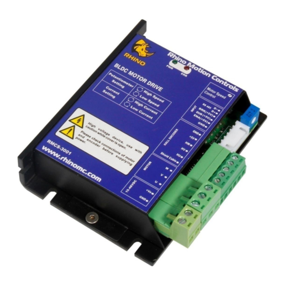
Rhino Motion Controls RMCS-3001 is 250W RTU Modbus high performance brushless dc drive. It supports (15–48V DC) and it is designed for optimized operation of Rhino brushless DC motors with Hall sensor. This is an amazing cost effective solution to provide closed loop/open loop control for various applications. The salient features of this drive: •... -
Page 4: Technical Specifications And Pin Description
Technical specifications and Pin description Supply Voltage and Current Specification Units Comments Supply Voltage Volts DC Between +Ve and GND Phase Current Amps Peak 5 Amps per phase Pin description of the drive is as per below image: Pin No. Description Pin No. -
Page 5: Modbus Registers
Modbus Registers Range Data Size /Command And Register Address Access Function Specification Description Default value in (Decimal) HEX (Decimal) To save parameters in Drive (EEPROM) send Hex value XXFF to Address 0. Write Parameters to FF (255) Where XX is slave ID ranging EEPROM from 1 to F7(1 - 247) Read /... - Page 6 Mode byte:03 0303(771) Brake Control byte:03 Analog Closed Loop Enable Minimum Speed Control Minimum Speed Mode byte:04 0401(1025) Mode. Set PWM speed in Control Mode Control byte:01 address 4. (Mode 4) Range: Set PWM for digital open loop 0000-12C0 Read / 40005 16 bit mode and analog minimum...
-
Page 7: Modbus Register Mapping
Modbus Register Mapping ➢ Device Modbus Address(MOD _ID) Address: 0x00 (40001) Default value: 0x01FF MOD_ID[15:8] SP[7:0] Bits 15:8 MOD_ID [15:8]: Modbus address register bits Default: 0x01 Maximum value: 0xF7 Minimum value: 0x01 Bits 7:0 SP [7:0]: Save parameters Default: 0x00 If slave id is 7 then by writing 07FF in this address will save parameters in eeprom and writing 0800 will load default value in drive. - Page 8 Bits 15:0 PWM [15:0]: PWM Default: 0x0000 Maximum value: 0x12C0 Minimum value: 0x0000 PWM Signal depends on the application. PWM range of this drive is 0-4800 (decimal) value. Set PWM for open loop mode. ➢ Frequency Register(FRQ) Address: 0x06 (40007) Default value: 0x0000 FRQ[15:0] Bits 15:0 FRQ [15:0]: Frequency...
-
Page 9: Control Modes
Control Modes Motor can be run in 5 different modes: Mode 0: Analog Open Loop Mode Mode 1: Digital Closed Loop Mode Mode 2: Digital Open Loop Mode Mode 3: Analog Closed Loop Mode Mode 4: Analog Closed Loop Minimum Speed Control Mode Hardware Connection: P a g e https://www.robokits.co.in/... - Page 10 10 | P a g e https://www.robokits.co.in/...
-
Page 11: Mode 0 Analog Open Loop Mode
Mode 0 Analog Open Loop Mode: In this mode the speed of the Rhino BLDC motor can be controlled by using Potentiometer which is available at the corner side of drive. User can increase or decrease the speed manually based on requirement by using Potentiometer. -
Page 12: Troubleshooting
Troubleshooting If motor is not moving in digital closed loop mode read value in frequency register. If motor is not moving in digital open loop mode read value in PWM register. If motor is not running in analog mode check external potentiometer connections and check enable connection as it must be connected with 5V. - Page 13 Copyright © Rhino Motion Controls, 2020 Neither the whole nor any part of the information contained in, or the product described in this manual, may be adapted or reproduced in any material or electronic form without the prior written consent of the copyright holder.
Need help?
Do you have a question about the RMCS – 3001 and is the answer not in the manual?
Questions and answers