Table of Contents
Advertisement
Quick Links
Advertisement
Table of Contents

Related Manuals for Lattice Semiconductor POWR607


Summary of Contents for Lattice Semiconductor POWR607
- Page 1 POWR607/6AT6 Evaluation Board User’s Guide July 2014 EB86_01.0...
-
Page 2: Software Requirements
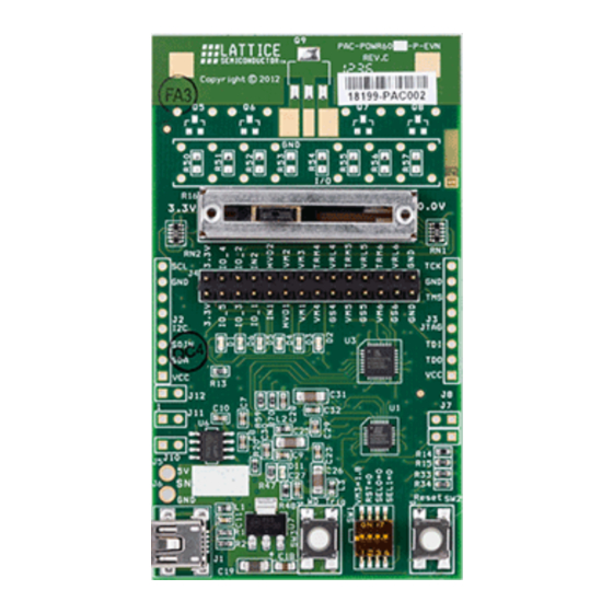
Note: Static electricity can severely shorten the lifespan of electronic components. See the POWR607/6AT6 Evalu- ation Board QuickSTART Guide for handling and storage tips. Features • POWR607/6AT6 Evaluation Board - A 3.75 by 2.00 inches form factor that features the following on-board com- ponents and circuits: ®... - Page 3 POWR607/6AT6 Evaluation Board Figure 1. POWR607/6AT6 Evaluation Board, Top Side Thru-Hole Prototype Area SMD Prototype Area Slide Potentiometer (R16) Expansion Header I2C Header JTAG Header PWR LED (D1) POWR6AT6 SEL1 LED (D6) SEL0 LED (D5) RST LED (D4) POWR607 CPU RESET LED (D2)
- Page 4 POWR607/6AT6 Evaluation Board Figure 2. POWR607/6AT6 Evaluation Board, Bottom Side Bottom SMD Prototype Area VMON Attenuation Networks...
-
Page 5: Demonstration Designs
Lattice provides two demos that illustrate key applications of the Power Manager II devices POWR607 and POWR6AT6: • Processor Support - Demonstrates the POWR607 as a power manager for a processor, DSP, ASSP, or ASIC. It integrates three functions traditionally covered by discrete ICs: voltage supervisor, reset generator, and watch- dog timer. - Page 6 Table 1 describes the DIP switch, push-button inputs, and slide potentiometer settings that control the pre-config- ured POWR607 and emulate a variety of processor support scenarios. Use them as a reference as you follow the procedure. To indicate a ‘1’ (logical True) on the DIP switch SW1, slide the switch towards the number indicated on the switch body.
- Page 7 Appends an additional 200 ms period to any processor/DSP reset output asserted by the POWR607. X1XX Programmable clock and timer functions of the POWR607 allow for a variety of timeout intervals from 32 1.96 sec in 128 steps. It may be necessary to connect a logic analyzer to detect the pulse us to stretch.
- Page 8 Many processor power management scenarios can be shown with the POWR607 evaluation board. Follow the pro- cedure below to emulate one particular case. 1. Set the POWR607 configuration to indicate 1.8 V Supply OK, disable reset pulse stretch and enable a two- sec- ond watchdog timer period. ...
-
Page 9: Download Demo Designs
Note that the POWR607 watchdog timer is also disabled. 7. Slide R16 toward the 3.3 V position. Once the POWR607 voltage monitor detects that the 2.5 V rail is above a threshold value of 2.5 V -5%, the Reset CPU output signal is released. The CPU Reset LED (D2) light goes out. - Page 10 Download Windows Hardware Drivers If you wish to reprogram the POWR607/6AT6 Evaluation Board, you will need to obtain the necessary hardware drivers for Windows. If your installation of Windows does not automatically install USB drivers when the evaluation board is connected to a USB port, then use the procedure below to download them from the Lattice web site.
- Page 11 This section describes the features of the POWR607/6AT6 evaluation board in detail. Overview The POWR607/6AT6 Evaluation Board is a complete development platform for the Lattice POWR607 mixed-signal device. The board includes circuitry to emulate a processor/DSP interface, a USB program/power port, SMD and thru-hole prototyping areas, and an expansion header to support test connections.
- Page 12 Power Manager II VMON_GS 3 POWR6AT6 JTAG ispPAC- Header POWR6AT6-01SN32I Table 2 describes the components on the board and the interfaces it supports. Table 2. POWR607/6AT6 Evaluation Board Components and Interfaces Component/Interface Type Schematic Reference Description Circuits Pulse Stretch Circuit Circuit...
- Page 13 3.3 V supply rails to VMON3 connection Expansion Header The expansion header provides 28user I/O’s connected to the POWR607 and POWR6AT6. The remaining pins serve as power for expansion boards. The expansion connector is configured as one 16x2 100mil centered pin header.
- Page 14 POWR607/6AT6 Evaluation Board J4 Pin Function POWR607 Pin POWR6AT6 Pin Other Connections HVOUT2 — — HVOUT1 — — VMON2 VMON2 VMON2 VMON1 VMON1 VMON1 VMON3 VMON3 VMON3 VMON4 VMON4 VMON4 TRM4 — DAC4 VMON4_GS — VMON4GS VRAIL4 — — Voltage supervisory circuit...
- Page 15 For power and programming, an FTDI USB UART/FIFO IC converter provides a communication interface between a PC host and the JTAG programming chain of the POWR607 board. The USB 5 V supply is also used as a source for the 3.3 V and 1.8 V supply rails. A USB B-type mini socket is provided for the USB connector cable.
- Page 16 POWR607/6AT6 Evaluation Board POWR607 The POWR607 device (ispPAC-POWR607) on the board integrates voltage supervisor, watchdog timer, and reset generator functions in a 4x4 mm chip scale package Table 11. POWR607 PLD Reference Item Description Reference Designators Part Number ispPAC-POWR607-01-SN24I Manufacturer...
- Page 17 POWR607/6AT6 Evaluation Board POWR6AT6 The POWR6AT6 device (ispPAC-POWR6AT6) on the board provides power supply margin and trim functions, ana- log input monitoring with an embedded 10-bit ADC in a 5x5 mm quad flat-pack package. Table 13. POWR6AT6 Reference Item Description...
- Page 18 The board has two momentary push-button switches (SW2 and SW3) to support the pre-loaded processor support demo. SW2 is tied to a POWR607 input pin (IN1) which asserts the Reset input. SW3 is tied to a POWR607 input pin (IN2) which asserts the watchdog trigger (WD_Trig) input. You may use SW2/SW3 for user-defined inputs for your own custom POWR607 designs.
- Page 19 This section describes how to selectively bypass the POWR607 or POWR6AT6 devices in the JTAG programming chain. 1. JTAG TMS bypass: Remove R42 (POWR607 TMS) or R41 (POWR6AT6 TMS) to bypass either device. To reverse the bypass you may install jumpers at locations J10 or J11 to reconnect the TMS circuit (Schematic Sheet 1 of 6).
- Page 20 POWR607/6AT6 Evaluation Board Glossary CPLD: Complex Programmable Logic Device DIP: Dual in-line package. C: Inter-Integrated Circuit. LED: Light Emitting Diode. Mixed-Signal PLD: A PLD integrated with analog and mixed signal support circuitry. PCB: Printed Circuit Board. RoHS: Restriction of Hazardous Substances Directive.
-
Page 21: Ordering Information
01.0 Initial release. © 2014 Lattice Semiconductor Corp. All Lattice trademarks, registered trademarks, patents, and disclaimers are as listed at www.latticesemi.com/legal. All other brand or product names are trademarks or registered trademarks of their respective holders. The specifications and information herein are subject to change without notice. -
Page 22: Appendix A. Schematics
POWR607/6AT6 Evaluation Board Appendix A. Schematics Figure 5. Power Manager 605, 607 and 6AT6... - Page 23 POWR607/6AT6 Evaluation Board Figure 6. USB to JTAG and I C Interface...
- Page 24 POWR607/6AT6 Evaluation Board Figure 7. Power Supply...
- Page 25 POWR607/6AT6 Evaluation Board Figure 8. LEDs and Switches...
- Page 26 POWR607/6AT6 Evaluation Board Figure 9. (Optional) JTAG, I C and Test Headers...
- Page 27 POWR607/6AT6 Evaluation Board Figure 10. Prototype Area...
-
Page 28: Appendix B. Bill Of Materials
POWR607/6AT6 Evaluation Board Appendix B. Bill of Materials Table 15. Bill of Materials Item Quantity Reference Part Number ispPAC-POWR607 ispPAC-POWR605 ispPAC-POWR6AT6 M93C46-WMN6TP NCP1117ST33T3G FT2232H LTST-C190TBKT LTST-C190CKT D3-D6,D11 LTST-C190AKT 1N4148 C1-10, 20-22,23,27-30,32 ECJ-1VB1C104K C11,12 ECJ-1VB1C103K C15,16 ECJ-1VB1C103K C25,26,31 ECJ-1VB1C475K C30-32 ECJ-1VB1C104K... - Page 29 Table 16. Optional Parts Item Quantity Reference Part Number J7-J12 J2, J3 J5, J6 R27-R29 ERJ-3GEYJ472V R39,R40 ERJ-3GEYJ103V R50-57,R60-69 ERJ-3GEYJ102V Q2,Q3 MMBT2369A Q5-Q15 FDV301N D7-D9 MAZ80510GML R21-R26...
- Page 30 Mouser Electronics Authorized Distributor Click to View Pricing, Inventory, Delivery & Lifecycle Information: Lattice PACPOWR607-P-EVN...
Need help?
Do you have a question about the POWR607 and is the answer not in the manual?
Questions and answers