
Related Manuals for Lattice Semiconductor ispMACH 4000ZE Pico


Summary of Contents for Lattice Semiconductor ispMACH 4000ZE Pico
- Page 1 ispMACH 4000ZE Pico Development Kit User’s Guide September 2009 Revision: EB47_01.0...
- Page 2 Features The ispMACH 4000ZE Pico Development Kit includes: • ispMACH 4000ZE Pico Evaluation Board - The Pico board is a 2.5” x 2” form factor that features the following on-board components and circuits: – ispMACH 4256ZE CPLD (LC4256ZE-5MN144C) –...
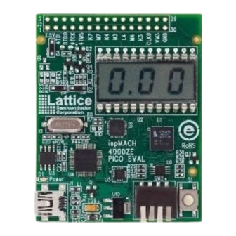
- Page 3 4000ZE Pico Development Kit Lattice Semiconductor User’s Guide Figure 1. Pico Evaluation Board, Top Side Figure 2. Pico Evaluation Board, Bottom Side...
-
Page 4: Software Requirements
4000ZE Pico Development Kit Lattice Semiconductor User’s Guide Software Requirements Install the following software before you begin developing designs for the evaluation board: ® • ispLEVER Classic 1.3 (ispMACH 4000ZE CPLD support) ® • PAC-Designer 5.1 (ispPAC-POWR6AT6 mixed-signal PLD support) •... - Page 5 4000ZE Pico Development Kit Lattice Semiconductor User’s Guide Figure 3. Pico Power Demo Block Diagram ispMACH 4256ZE 4-bit DIP Input Switch Control Up/Down Counter Right/Left 3-char 7-seg Shift Register Master Clock 5 MHz Generator < 2 Hz POWR6AT6 POWR6AT6...
- Page 6 4000ZE Pico Development Kit Lattice Semiconductor User’s Guide Switch 1234 (Demo) Pico Power Demo Features 0000 (Up) Decimal Up/Down Counter Display – Displays an 8-bit decimal up/down counter (0.0-9.9) using 0001 (Down) the <2 Hz clock generated by the LC4256ZE On-Chip Oscillator and Timer (OSCTIMER). A 4-bit nibble is committed to the “ones”...
-
Page 7: I 2 C Gpio Expansion Demo
4000ZE Pico Development Kit Lattice Semiconductor User’s Guide 3. Select Switch bank pattern 0000 (decimal up counter). The LCD displays a decimal up-counter. The counter uses a divided OSCTIMER clock source set for 5 kHz nominal (TIMER_DIV=1024). 5 kHz is further divided to produce a count frequency of < 2 Hz. Use the voltme- ter technique in step 1 to measure core current. - Page 8 4000ZE Pico Development Kit Lattice Semiconductor User’s Guide Download PicoView Software and I C GPIO Expansion Demo The following steps require a host PC with a USB port configured to communicate with the Pico board. Before you begin, you will need to obtain the I...
- Page 9 4000ZE Pico Development Kit Lattice Semiconductor User’s Guide Run the I C GPIO Expansion Demo These instructions highlight the LC4256ZE providing general-purpose I/O for an I/O-constrained microprocessor or DSP. A host PC running the Lattice PicoView program emulates a processor reading and writing I C traffic to I slaves embedded in the LC4256ZE and POWR6AT6 devices.
-
Page 10: Hardware Evaluation
4000ZE Pico Development Kit Lattice Semiconductor User’s Guide Hardware Evaluation How to evaluate hardware features of the on-board LC4256ZE. Power Consumption Tables 1 and 2 list a series of measurements for the CPLD I/O and core current running the Pico Power demonstra- tion design when powered by battery or the USB cable interface. -
Page 11: Download Demo Designs
Use the procedure described below to recompile any of the LC4256ZE demo projects for the Pico Evaluation Board. 1. Install and license ispLEVER Classic software. 2. Download the demo source files from the ispMACH 4000ZE Pico Development Kit web page. 3. Run the ispLEVER Classic Project Navigator. 4. Open the <demo>.syn project file. -
Page 12: Programming With Ispvm
Lattice Semiconductor User’s Guide 1. Install and license PAC-Designer software 2. Download the demo source files from the ispMACH 4000ZE Pico Development Kit web page. 3. Run PAC-Designer. 4. Open the <demo>.pac project file. 5. Choose File > Export… The Export dialog appears. -
Page 13: Picoview Software
4000ZE Pico Development Kit Lattice Semiconductor User’s Guide 7. Browse to the <Demo Dir>\project folder, select <Demo>.jed, and click Open. From the Operation list choose Erase, Program, Verify and click OK. Optional: Choose the Bypass operation for devices in the scan chain that don’t require re-programming. - Page 14 4000ZE Pico Development Kit Lattice Semiconductor User’s Guide PicoView Window The PicoView window provides access to control and status registers and a series or read or write actions that can be issued by the I C bus master module emulated by PicoView.
-
Page 15: Ispmach 4000Ze Pico Evaluation Board
Function: Specify the initial shift-register load pattern for the right-most 7-segment digit of the LCD panel. ispMACH 4000ZE Pico Evaluation Board This section describes the features of the ispMACH 4000ZE Pico evaluation board in detail. Overview The Pico board is a complete development platform for the LC4256ZE CPLD. The board includes a high-side cur- rent sensor circuit, a Power Manager II ispPAC-POWR6AT6 mixed-signal PLD, a USB program/power port, and an expansion header landing to support test connections. - Page 16 4000ZE Pico Development Kit Lattice Semiconductor User’s Guide Figure 8. ispMACH 4000ZE Pico Evaluation Board Block Diagram GPIO 2X16 4-bit DIP Header Switch Current ispPAC- Sense Circuit POWR6AT6 ispMACH4256ZE- MN144 A/Mini-B USB Cable JTAG Programming USB Mini-B 3-char 7-seg...
- Page 17 4000ZE Pico Development Kit Lattice Semiconductor User’s Guide Clock Sources All clocks for the Pico Power and GPIO I C demonstration designs originate from the LC4256ZE CPLD on-chip oscillator and timer (OSCTIMER) block. You may use the expansion header landing to drive a CPLD input with an external clock source.
- Page 18 4000ZE Pico Development Kit Lattice Semiconductor User’s Guide 4K_TCK USB_TCK 4K_TMS USB_TMS PROTO_K7 USB_SDA PROTO_M7 USB_SCL PROTO_K4 PROTO_L7 PROTO_M3 PROTO_L8 PROTO_L4 PROTO_M8 PROTO_M4 PROTO_M9 PROTO_K3 PROTO_L9 CLK0_MACH CLK0 PROTO_K8 VMON_3 VMON_4 ispMACH4256ZE-MN144 CPLD The ispMACH4256ZE-MN144 is a 144-ball csBGA package CPLD device which provides 108 I/Os and 4 dedicated inputs in a 7 x 7mm package.
- Page 19 4000ZE Pico Development Kit Lattice Semiconductor User’s Guide Table 11. JTAG Programming Pin Information Description LC4256ZE Pin POWR6AT6 Pin/Net Test Data Output B11:TDO / 4K_TDO 4:TDI / 6AT6_TDI Test Data Output 1:TDO / 6AT6_TDO Test Data Input A1:TDI / 4K_TDI...
-
Page 20: Modifying The Pico Board
System software as if a regular parallel-type ispDOWNLOAD™ cable is connected to the PC. Modifying the Pico Board The ispMACH 4000ZE Pico evaluation board provides landing areas for additional circuits to support the following functions: • Rechargeable Lithium-Ion 20 mA rechargeable battery •... -
Page 21: Troubleshooting
4000ZE Pico Development Kit Lattice Semiconductor User’s Guide Environmental Requirements The evaluation board must be stored between -40°C and 100°C. The recommended operating temperature is between 0°C and 90°C. The evaluation board can be damaged without proper anti-static handling. -
Page 22: Ordering Information
01.0 Initial release. © 2009 Lattice Semiconductor Corp. All Lattice trademarks, registered trademarks, patents, and disclaimers are as listed at www.latticesemi.com/legal. All other brand or product names are trademarks or registered trademarks of their respective holders. The speci• cations and information herein are subject to change without notice. -
Page 23: Appendix A. Schematics
4000ZE Pico Development Kit Lattice Semiconductor User’s Guide Appendix A. Schematics Figure 9. ispMACH 4000ZE Bank 0 and 3-Digit LCD... - Page 24 4000ZE Pico Development Kit Lattice Semiconductor User’s Guide Figure 10. ispMACH 4000ZE Bank 1, DIP, SW, Expansion Header...
- Page 25 4000ZE Pico Development Kit Lattice Semiconductor User’s Guide Figure 11. USB 5V to 3.3V, ispMACH 4000ZE Power Rails 3.0V Batt, 1.8V Rail and Current Monitors...
- Page 26 4000ZE Pico Development Kit Lattice Semiconductor User’s Guide Figure 12. USB to JTAG and I C for the ispMACH 4000ZE and ispPAC-POWR6AT6...
- Page 27 4000ZE Pico Development Kit Lattice Semiconductor User’s Guide Figure 13. ispPAC-POWR6AT6 and Current Sense Amplifiers...
-
Page 28: Appendix B. Bill Of Materials
4000ZE Pico Development Kit Lattice Semiconductor User’s Guide Appendix B. Bill of Materials Table 17. Bill of Materials Item Quantity Reference Part Number C19, C20 ECJ-0EC1H120J C21, C22 ECJ-0EC1H330J C23, C24, C25, C26 ECJ-0EB1E103K ECJ-0EB1A333K C1-C18, C33, C34, C35... - Page 29 4000ZE Pico Development Kit Lattice Semiconductor User’s Guide Table 17. Bill of Materials (Continued) 193-4MS Q1, Q2, Q3 IRLML6402PBF MMBT2222LT1G IRLML2502TRPBF MMBT3906LT1G HCM49 6.000MABJ-UT LTST-C190TBKT D2, D3, D4 1N4148W-TP BATHLD001 CR2032 SJ61A3 Notes: 1. Quantity 0 (zero) indicates an optional component. See the Modifying the Pico Board section for more information.
Need help?
Do you have a question about the ispMACH 4000ZE Pico and is the answer not in the manual?
Questions and answers