
Related Manuals for Emerson Micro-Motion 2400S


Summary of Contents for Emerson Micro-Motion 2400S
- Page 1 Configuration and Use Manual P/N 20004436, Rev. AB October 2009 ® Micro Motion Model 2400S Transmitters with Analog Outputs Configuration and Use Manual...
- Page 2 © 2009 Micro Motion, Inc. All rights reserved. The Micro Motion and Emerson logos are trademarks and service marks of Emerson Electric Co. Micro Motion, ELITE, MVD, ProLink, MVD Direct Connect, and PlantWeb are marks of one of the Emerson Process...
-
Page 3: Table Of Contents
Contents Chapter 1 Before You Begin ........1 Overview . - Page 4 Contents Chapter 5 Flowmeter Startup ........23 Overview .
- Page 5 Contents Handling status alarms ..........62 7.5.1 Using the display menus .
- Page 6 Contents Chapter 9 Pressure Compensation, Temperature Compensation, and Polling ........95 Overview .
- Page 7 Contents 11.18 Checking the sensor tubes ......... . . 147 11.19 Checking output saturation .
- Page 8 ® Micro Motion Model 2400S Transmitters with Analog Outputs...
-
Page 9: Chapter 1 Before You Begin
Chapter 1 Before You Begin Overview This chapter provides an orientation to the use of this manual, and includes a pre-configuration worksheet. This manual describes the procedures required to start, configure, use, maintain, and troubleshoot the Model 2400S transmitter with analog outputs (the Model 2400S AN transmitter). If you do not know what transmitter you have, see Section 1.3 for instructions on identifying the transmitter type from the model number on the transmitter’s tag. -
Page 10: Determining Version Information
Micro Motion web site (www.micromotion.com). You may be able to use other tools from Emerson Process Management, such as AMS Suite: Intelligent Device Manager. Use of AMS is not discussed in this manual; however, the user interface that AMS provides is similar to the ProLink II user interface. -
Page 11: Planning The Configuration
Before You Begin Planning the configuration The pre-configuration worksheet in Section 1.8 provides a place to record information about your flowmeter (transmitter and sensor) and your application. This information will affect your configuration options as you work through this manual. Fill out the pre-configuration worksheet and refer to it during configuration. -
Page 12: Micro Motion Customer Service
In the U.K., phone 0870 240 1978 (toll-free) In other locations, phone +31 (0) 318 495 555 (The Netherlands) Customers outside the U.S.A. can also email Micro Motion customer service at flow.support@emerson.com. ® Micro Motion Model 2400S Transmitters with Analog Outputs... -
Page 13: Chapter 2 Using The Transmitter User Interface
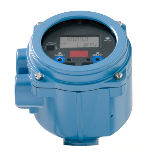
Chapter 2 Using the Transmitter User Interface Overview This chapter describes the user interface of the Model 2400S AN transmitter. The following topics are discussed: • Transmitters without or with display – see Section 2.2 • Removing and replacing the transmitter housing cover – see Section 2.3 •... - Page 14 Using the Transmitter User Interface Figure 2-1 User interface – Transmitters without display Zero button Status LED HART security switch Service port clips HART clips Figure 2-2 User interface – Transmitters with display LCD panel Current value Status LED Process variable HART security switch Unit of measure Optical switch indicator...
-
Page 15: Removing And Replacing The Transmitter Housing Cover
Using the Transmitter User Interface Removing and replacing the transmitter housing cover For some procedures, you must remove the transmitter housing cover. To remove the transmitter housing cover: 1. If the transmitter is in a Division 2 or Zone 2 area, remove power from the unit. WARNING Removing the transmitter housing cover in a Division 2 or Zone 2 area while the transmitter is powered up can cause an explosion. -
Page 16: Viewing Process Variables
Using the Transmitter User Interface Due to software and hardware restrictions, some English words and terms may appear in the non-English display menus. For a list of the codes and abbreviations used on the display, see Appendix D. For information on configuring the display language, see Section 8.10. In this manual, English is used as the display language. -
Page 17: Display Password
Using the Transmitter User Interface To exit a menu without making any changes • Use the option if available. EXIT • Otherwise, activate at the confirmation screen. Scroll 2.5.4 Display password Some of the display menu functions, such as accessing the off-line menu, can be protected by a display password. - Page 18 Using the Transmitter User Interface Select to move one digit to the left. As you move from one digit to the next, a decimal point will flash between each digit pair. 4. When the decimal point is in the desired position, Scroll.
-
Page 19: Using The Hart Security Switch
Using the Transmitter User Interface Using the HART security switch The HART security switch is the upper switch at the left side of the display (see Figures 2-1 and 2-2). Note: The lower switch is not used by the Model 2400S AN transmitter. When the HART security switch is set to the On (right) position, HART protocol cannot be used to perform any action that requires writing to the transmitter. - Page 20 ® Micro Motion Model 2400S Transmitters with Analog Outputs...
-
Page 21: Connecting With Prolink Ii Or Pocket Prolink Software
Chapter 3 Connecting with ProLink II or Pocket ProLink Software Overview ProLink II is a Windows-based configuration and management tool for Micro Motion transmitters. It provides complete access to transmitter functions and data. Pocket ProLink is a version of ProLink II that runs on a Pocket PC. -
Page 22: Connecting From A Pc To A Model 2400S An Transmitter
Connecting with ProLink II or Pocket ProLink Software Connecting from a PC to a Model 2400S AN transmitter Protocol options for ProLink II or Pocket ProLink connections to the Model 2400S AN transmitter are listed in Table 3-1. Note: Due to the design of HART protocol, connections made using HART protocol are slower than connections that use Modbus protocol. - Page 23 Connecting with ProLink II or Pocket ProLink Software Making the connection To connect to the service port: 1. If you are using the infrared port, position the infrared device for communication with the infrared port (see Figure 2-2). You do not need to remove the transmitter housing cover. Note: The infrared port is typically used with Pocket ProLink.
-
Page 24: Connecting To The Hart Clips Or To A Hart Multidrop Network
Connecting with ProLink II or Pocket ProLink Software 3. Start ProLink II or Pocket ProLink software. From the Connection menu, click on Connect to . In the screen that appears, specify: Device • Protocol : as appropriate for your connection type •... - Page 25 Connecting with ProLink II or Pocket ProLink Software Figure 3-2 HART/Bell 202 connections to HART network See Step 4 DCS or See Step 4 See Step 4 3. To connect to the HART clips: a. Remove the transmitter housing cover (see Section 2.3). b.
-
Page 26: Prolink Ii Language
Connecting with ProLink II or Pocket ProLink Software 5. Start ProLink II or Pocket ProLink software. From the Connection menu, click on Connect to Device 6. In the screen that appears: a. Set , and are automatically set to Protocol HART Bell 202 Baud rate Stop bits... -
Page 27: Connecting With The 375 Field Communicator
Chapter 4 Connecting with the 375 Field Communicator Overview The 375 Field Communicator is a handheld configuration and management tool for HART-compatible devices, including Micro Motion transmitters. It provides complete access to transmitter functions and data. This chapter provides basic information for connecting the 375 Field Communicator to your transmitter. -
Page 28: Connecting To A Transmitter
Connecting with the 375 Field Communicator Connecting to a transmitter You can connect the Communicator to the transmitter’s HART clips or to a point on a HART network. Note: The HART clips on the face of the transmitter are connected to the transmitter’s mA/HART terminals. -
Page 29: Connecting To A Multidrop Network
Connecting with the 375 Field Communicator Figure 4-1 Connecting to HART clips HART clips 250–600 Ω resistance Communicator 4.3.2 Connecting to a multidrop network The Communicator can be connected to any point in a multidrop network. See Figure 4-2. Ω The Communicator must be connected across a resistance of 250–600 . - Page 30 ® Micro Motion Model 2400S Transmitters with Analog Outputs...
-
Page 31: Flowmeter Startup
Chapter 5 Flowmeter Startup Overview This chapter describes the procedures you should perform the first time you start the flowmeter system. You do not need to use these procedures every time you cycle power to the transmitter. The following procedures are discussed: •... -
Page 32: Applying Power
Flowmeter Startup Applying power Before you apply power to the flowmeter, close and tighten all covers. WARNING Operating the flowmeter without covers in place creates electrical hazards that can cause death, injury, or property damage. To avoid electrical hazards, ensure that the warning flap and transmitter housing cover are in place before applying power to the transmitter. - Page 33 Flowmeter Startup Note the following: • If your transmitter does not have a display, you must use ProLink II or the Communicator. • The Communicator does not provide a loop test for the discrete input. • The mA reading does not need to be exact. You will correct differences when you trim the mA output.
- Page 34 Flowmeter Startup Figure 5-2 Display – Loop test procedure ® Micro Motion Model 2400S Transmitters with Analog Outputs...
- Page 35 Flowmeter Startup Figure 5-3 ProLink II – Loop test procedure ProLink Menu > Test Fix Milliamp 1/2 Fix Freq Out Fix Discrete Output Read Discrete Input Toggle remote input Enter mA value Enter Hz value ON or OFF device Fix mA Fix Frequency Read output at Read output at...
-
Page 36: Trimming The Milliamp Output
Flowmeter Startup Trimming the milliamp output Trimming the mA output creates a common measurement range between the transmitter and the device that receives the mA output. For example, a transmitter might send a 4 mA signal that the receiving device reports incorrectly as 3.8 mA. If the transmitter output is trimmed correctly, it will send a signal appropriately compensated to ensure that the receiving device actually indicates a 4 mA signal. - Page 37 Flowmeter Startup Figure 5-6 Communicator – mA output trim procedure On-Line Menu > 3 Diag/Service > 6 Trim Analog Out 1/2 4 mA trim 20 mA trim Read mA output at Read mA output at receiving device receiving device Enter receiving device Enter receiving device value at Communicator value at Communicator...
-
Page 38: Zeroing The Flowmeter
Flowmeter Startup Zeroing the flowmeter Zeroing the flowmeter establishes the flowmeter’s point of reference when there is no flow. The meter was zeroed at the factory, and should not require a field zero. However, you may wish to perform a field zero to meet local requirements or to confirm the factory zero. -
Page 39: Zero Procedure
Flowmeter Startup 5.5.2 Zero procedure To zero the flowmeter: • Using the display menu, see Figure 5-8. For a complete illustration of the display zero menu, see Figure C-16. • Using the zero button, see Figure 5-9. • Using ProLink II, see Figure 5-10. •... - Page 40 Flowmeter Startup Figure 5-8 Display menu – Flowmeter zero procedure Scroll and Select simultaneously for 4 seconds Scroll OFF-LINE MAINT Select Scroll ZERO Select ZERO/YES? Select …………………. CAL FAIL CAL PASS Troubleshoot Select ZERO Scroll EXIT Figure 5-9 Zero button – Flowmeter zero procedure Press ZERO button Status LED flashes yellow...
- Page 41 Flowmeter Startup Figure 5-10 ProLink II – Flowmeter zero procedure ProLink > Calibration > Zero Calibration Modify zero time if required Perform Auto Zero Calibration in Progress LED turns red Wait until Calibration in Progress LED turns green Calibration Green Failure LED Done Troubleshoot...
- Page 42 ® Micro Motion Model 2400S Transmitters with Analog Outputs...
-
Page 43: Required Transmitter Configuration
Chapter 6 Required Transmitter Configuration Overview This chapter describes the configuration procedures that are usually required when a transmitter is installed for the first time. The following procedures are discussed: • Characterizing the flowmeter – see Section 6.2 • Configuring transmitter channels – see Section 6.3 •... -
Page 44: Characterizing The Flowmeter
Required Transmitter Configuration Characterizing the flowmeter Characterizing the flowmeter adjusts the transmitter to compensate for the unique traits of the sensor it is paired with. The characterization parameters, or calibration parameters, describe the sensor’s sensitivity to flow, density, and temperature. 6.2.1 When to characterize If the transmitter and sensor were ordered together, then the flowmeter has already been... -
Page 45: How To Characterize
Required Transmitter Configuration Figure 6-1 Sample calibration tags T-Series Other sensors 19.0005.13 12500142864.44 12502.000 0.0010 14282.000 0.9980 4.44000 Flow calibration values The flow calibration factor is a 10-character string that includes two decimal points. In ProLink II, this value is called the Flowcal parameter; in the Communicator, it is called the FCF for T-Series sensors, and Flowcal for other sensors. -
Page 46: Configuring Transmitter Channels
Required Transmitter Configuration Figure 6-2 Characterizing the flowmeter ProLink II Communicator ProLink > On-Line Menu > Configuration 5 Detailed Setup Device 1 Charize sensor · Sensor type 1 Sensor type Straight Curved Sensor type? tube tube 3 Flow Flow Flow 4 Density Density Density... -
Page 47: Configuring The Measurement Units
Required Transmitter Configuration Figure 6-3 Configuring the channels Display ProLink II Communicator ProLink > Off-line maint > On-Line Menu > Configuration Off-line config 5 Detailed Setup Channel 3 Config outputs 1 Channel setup CH A CH B Power Set MA / FO / DO / DI 2 Channel A setup 3 Channel B setup Power... -
Page 48: Volume Flow Units
Required Transmitter Configuration Table 6-2 Mass flow measurement units Mass flow unit Display ProLink II Communicator Unit description Grams per second G/MIN g/min g/min Grams per minute g/hr Grams per hour KG/S kg/s kg/s Kilograms per second KG/MIN kg/min kg/min Kilograms per minute KG/H kg/hr... - Page 49 Required Transmitter Configuration Table 6-3 Volume flow measurement units – Liquid Volume flow unit Display ProLink II Communicator Unit description CUFT/S ft3/sec Cuft/s Cubic feet per second CUF/MN ft3/min Cuft/min Cubic feet per minute CUFT/H ft3/hr Cuft/h Cubic feet per hour CUFT/D ft3/day Cuft/d...
-
Page 50: Density Units
Required Transmitter Configuration Table 6-4 Volume flow measurement units – Gas Volume flow unit Display ProLink II Communicator Unit description NM3/S Nm3/sec Not available Normal cubic meters per second NM3/MN Nm3/min Not available Normal cubic meters per minute NM3/H Nm3/hr Not available Normal cubic meters per hour NM3/D... -
Page 51: Temperature Units
Required Transmitter Configuration 6.4.4 Temperature units The default temperature measurement unit is ° . See Table 6-6 for a complete list of temperature measurement units. Table 6-6 Temperature measurement units Temperature unit Display ProLink II Communicator Unit description ° ° degC Degrees Celsius °... -
Page 52: Configuring The Ma Output
Required Transmitter Configuration Table 6-7 Pressure measurement units continued Pressure unit Display ProLink II Communicator Unit description megapascals Megapascals TORR Torr torr Torr @ 0 °C @ 0C atms atms Atmospheres Configuring the mA output The Model 2400S AN transmitter has one mA output. Table 6-8 lists the parameters that must be set for the mA output, and shows the names used for each parameter by the display, ProLink II, and the Communicator. -
Page 53: Configuring The Process Variable
Required Transmitter Configuration 6.5.1 Configuring the process variable You can configure the process variable to be reported through the mA output. Table 6-9 lists the process variables that can be assigned to the mA output. Table 6-9 mA output process variable assignments Process variable ProLink II code Communicator code... -
Page 54: Configuring Added Damping
Required Transmitter Configuration Multiple cutoffs Cutoffs can also be configured for the mass flow and volume flow process variables (see Section 8.4). If mass flow or volume flow has been assigned to the mA output, a non-zero value is configured for the flow cutoff, and the AO cutoff is also configured, the cutoff occurs at the highest setting, as shown in the following examples. -
Page 55: Configuring The Fault Indicator And Fault Value
Required Transmitter Configuration Multiple damping parameters Damping can also be configured for the flow (mass and volume), density, and temperature process variables (see Section 8.5). If one of these process variables has been assigned to the mA output, a non-zero value is configured for its damping, and added damping is also configured for the mA output, the effect of damping the process variable is calculated first, and the added damping calculation is applied to the result of that calculation. -
Page 56: Configuring The Frequency Output
Required Transmitter Configuration Configuring the frequency output Note: This section is applicable only if Channel B has been configured as a frequency output. See Section 6.3. The frequency output generates two voltage levels: • • A site-specific voltage, determined by the power supply, pull-up resistor, and load (see the installation manual for your transmitter) If Channel B is configured as a frequency output, you must configure the parameters listed in Table 6-11. -
Page 57: Configuring The Process Variable
Required Transmitter Configuration 6.6.1 Configuring the process variable Table 6-12 lists the process variables that can be assigned to the frequency output. Table 6-12 Frequency output process variable assignments Communicator Process variable ProLink II code code Display code Mass flow Mass Flow Mass flo MFLOW... -
Page 58: Configuring The Maximum Pulse Width
Required Transmitter Configuration The resulting TV Frequency Factor value must be within the range of the frequency output (0 to 10,000 Hz). • If the TV Frequency Factor value is less than 1 Hz, reconfigure the receiving device for a higher pulses/unit setting. -
Page 59: Configuring The Frequency Output Polarity
Required Transmitter Configuration Crossover frequency --------------------------------------------------- - × max pulse width • At frequencies below the crossover frequency, the duty cycle is determined by the pulse width and the frequency. • At frequencies above the crossover frequency, the output changes to a 50% duty cycle. You can change the setting for Maximum Pulse Width so that the transmitter will output a pulse width appropriate to your receiving device: •... -
Page 60: Configuring The Fault Indicator
Required Transmitter Configuration 6.6.5 Configuring the fault indicator If the transmitter encounters an internal fault condition, it will indicate the fault by sending a preprogrammed output level to the receiving device. You can specify the output level by configuring the fault indicator. See Table 6-15. Note: By default, the transmitter immediately reports a fault when a fault is encountered. -
Page 61: Polarity
Required Transmitter Configuration If Channel B is configured as a discrete output, you must configure the parameters listed in Table 6-16. Table 6-16 also shows the names used for each parameter by the display, ProLink II, and the Communicator. Table 6-16 Discrete output configuration parameters Parameter name ProLink II... -
Page 62: Assignment
Required Transmitter Configuration Table 6-17 Discrete output polarity Polarity Output power supply Description Active high Internal • When asserted (condition tied to DO is true), the circuit provides a pull-up to 24 V. • When not asserted (condition tied to DO is false), the circuit provides 0 V. -
Page 63: Fault Action
Required Transmitter Configuration The flow switch has a 5% hysteresis. For example, if the setpoint is 100 lb/min, the flow switch will be triggered when the flow rate falls below 100 lb/min, but not turned off until a 5% (5 lb/min) change occurs (i.e., the flow rate rises to 105 lb/min). -
Page 64: Assignment
Required Transmitter Configuration Figure 6-11 Configuring the discrete input ProLink II Communicator Display ProLink > On-Line Menu > Off-line maint > Configuration 5 Detailed Setup Off-line config Discrete Input 3 Config outputs 7 Discrete actions CH B 1 Channel setup 1 Assign discretes Set DI 6 DI/DO setup... - Page 65 Required Transmitter Configuration Table 6-22 Discrete input polarity Polarity Input power supply DI status Description Active high Internal Voltage across terminals is high Voltage across terminals is zero External Voltage applied across terminals is 3–30 VDC Voltage applied across terminals is <0.8 VDC Active low Internal Voltage across terminals is zero...
- Page 66 ® Micro Motion Model 2400S Transmitters with Analog Outputs...
-
Page 67: Using The Transmitter
Chapter 7 Using the Transmitter Overview This chapter describes how to use the transmitter in everyday operation. The following topics and procedures are discussed: • Recording process variables – see Section 7.2 • Viewing process variables – see Section 7.3 •... -
Page 68: Viewing Process Variables
Using the Transmitter Viewing process variables Process variables include measurements such as mass flow rate, volume flow rate, mass total, volume total, temperature, and density. You can view process variables with the display (if your transmitter has a display), ProLink II, or the Communicator. -
Page 69: Viewing Transmitter Status
Using the Transmitter Viewing transmitter status You can view transmitter status using the status LED, ProLink II, or the Communicator. Depending on the method chosen, different information is displayed. 7.4.1 Using the status LED All Model 2400S AN transmitters have a status LED. The status LED is located on the user interface board (see Figures 2-1 and 2-2). -
Page 70: Handling Status Alarms
Using the Transmitter Handling status alarms Specific process or flowmeter conditions cause status alarms. Each status alarm has an alarm code. Status alarms are classified into three severity levels: Fault, Information, and Ignore. Severity level controls how the transmitter responds to the alarm condition. Note: Some status alarms can be reclassified, i.e., configured for a different severity level. -
Page 71: Using Prolink Ii
Using the Transmitter 7.5.2 Using ProLink II ProLink II provides two ways to view alarm information: • The Status window displays the current status of all possible alarms, including Ignore alarms. A green LED indicates “inactive” and a red LED indicates “active.” The acknowledgment status bit is not shown, and you cannot acknowledge alarms from the Status window. -
Page 72: Using The Totalizers And Inventories
Using the Transmitter The Communicator also maintains an alarm log. The alarm log contains one record for each of the fifty most recent active Fault and Information status alarms. Ignore alarms are not listed. Each record contains: • The alarm code •... -
Page 73: Controlling Totalizers And Inventories
Using the Transmitter Figure 7-1 Totalizer values on display Current value Process variable Unit of measure optical switch Scroll optical switch Select With ProLink II To view current totals for the totalizers and inventories with ProLink II: 1. Click ProLink 2. - Page 74 Using the Transmitter Table 7-2 Totalizer and inventory control methods Function name Communicator ProLink II Display Start/stop all totalizers and inventories Reset mass totalizer value only Reset volume (liquid or gas) totalizer only Simultaneously reset all totalizer values Simultaneously reset all inventory values Reset mass inventory value only Reset volume (liquid or gas) inventory value only (1) Transmitters with display only.
- Page 75 Using the Transmitter With ProLink II Table 7-4 shows how you can control the totalizers and inventories using ProLink II. Table 7-4 Totalizer and inventory control with ProLink II To accomplish this On the totalizer control screen... Stop all totalizers and inventories Click Stop Start all totalizers and inventories...
- Page 76 ® Micro Motion Model 2400S Transmitters with Analog Outputs...
-
Page 77: Chapter 8 Optional Configuration
Chapter 8 Optional Configuration Overview This chapter describes transmitter configuration parameters that may or may not be used, depending on your application requirements. For required transmitter configuration, see Chapter 6. Table 8-1 lists the parameters that are discussed in this chapter. Default values and ranges for the most commonly used parameters are provided in Appendix A. -
Page 78: Configuring Volume Flow Measurement For Gas
Optional Configuration Table 8-1 Configuration map continued Tool Topic Subtopic ProLink II Communicator Display Section ✓ ✓ ✓ Digital Modbus address 8.11.1 communication ✓ ✓ Modbus ASCII support settings ✓ ✓ HART address ✓ Loop current mode ✓ ✓ ✓ Infrared port write-protect 8.11.2 ✓... -
Page 79: Creating Special Measurement Units
Optional Configuration 8.2.1 Using the Gas Wizard The Gas Wizard is used to calculate the standard density of the gas that you are measuring. To use the Gas Wizard: 1. Click ProLink > Configure > Flow 2. Click the button. Gas Wizard 3. -
Page 80: Special Measurement Unit For Mass Flow
Optional Configuration The preceding terms are related by the following formulae: x BaseUnit(s) y SpecialUnit(s) x BaseUnit(s) ConversionFactor -------------------------------------------- - y SpecialUnit(s) To create a special unit, you must: 1. Identify the simplest base volume or mass and base time units for your special mass flow or volume flow unit. -
Page 81: Special Measurement Unit For Liquid Volume Flow
Optional Configuration 8.3.3 Special measurement unit for liquid volume flow To create a special measurement unit for liquid volume flow: • Using ProLink II, see Figure C-3. Before configuring the special measurement unit, ensure that Vol Flow Type is set to Liquid Volume (see Figure C-2). -
Page 82: Cutoffs And Volume Flow
Optional Configuration To configure cutoffs: • Using ProLink II, see Figure C-2. • Using the Communicator, see Figure C-7. Note: This functionality is not available via the display menus. Table 8-2 Cutoff default values Cutoff type Default Comments Mass flow 0.0 g/s Recommended setting: 5% of the sensor’s rated maximum flowrate Volume flow... -
Page 83: Damping And Volume Measurement
Optional Configuration When you specify a new damping value, it is automatically rounded down to the nearest valid damping value. Valid damping values are listed in Table 8-3. Note: For gas applications, Micro Motion recommends a minimum flow damping value of 2.56. Before setting the damping values, review Sections 8.5.1 and 8.5.2 for information on how the damping values interact with other transmitter measurements and parameters. - Page 84 Optional Configuration Options for flow direction include: • Forward only • Reverse only • Absolute value • Bidirectional • Negate/Forward only • Negate/Bidirectional For the effect of flow direction on the mA output (i.e., flow variable has been assigned to the mA output): •...
- Page 85 Optional Configuration Figure 8-2 Effect of flow direction on mA output: 4 mA value < 0 –x –x –x Reverse Forward Reverse Forward Reverse Forward flow flow flow flow flow flow Zero flow Zero flow Zero flow Flow direction parameter: Flow direction parameter: Flow direction parameter: •...
- Page 86 Optional Configuration Example 2 Configuration: • Flow direction = Reverse Only • mA output: 4 mA = 0 g/s; 20 mA = 100 g/s (See the second graph in Figure 8-1.) As a result: • Under conditions of forward flow or zero flow, the mA output level is 4 mA.
-
Page 87: Configuring Events
Optional Configuration Table 8-4 Effect of flow direction on frequency output, discrete output, totalizers, and digital communications Forward flow Frequency Flow values via Flow direction value output Discrete output Flow totals digital comm. Forward only Increase Forward Increase Positive Reverse only 0 Hz Forward No change... -
Page 88: Defining Events
Optional Configuration Additionally, if your transmitter has a discrete output, you can configure a discrete output so that it is active if the event is ON, and inactive if the event is OFF (see Section 6.7). For example, the discrete output can open or close a valve according to event status. -
Page 89: Checking And Reporting Event Status
Optional Configuration Example Define Event 1 to stop all totalizers when the mass flow rate in forward or backward direction is less than 2 lb/min. 1. Specify lb/min as the mass flow unit. See Section 6.4.1. 2. Configure the Flow Direction parameter for bidirectional flow. See Section 8.6. -
Page 90: Configuring Fault Handling
Optional Configuration If the transmitter detects slug flow: • A slug flow alarm is posted immediately. • During the slug duration period, the transmitter holds the mass flow rate at the last measured pre-slug value, independent of the mass flow rate measured by the sensor. All outputs that report mass flow rate and all internal calculations that include mass flow rate will use this value. - Page 91 Optional Configuration Some alarms can be reclassified. For example: • The default severity level for Alarm A20 (calibration factors unentered) is , but you can Fault reconfigure it to either Informational Ignore • The default severity level for Alarm A102 (drive over-range) is Informational , but you can reconfigure it to either...
- Page 92 Optional Configuration Table 8-7 Status alarms and severity levels continued Communicator message Default Affected by Alarm code ProLink II message severity Configurable fault timeout A016 Line RTD Temperature Out-Of-Range Fault Line RTD Temperature Out-of-Range A017 Meter RTD Temperature Out-Of-Range Fault Meter RTD Temperature Out-of-Range A020 Calibration Factors Unentered...
-
Page 93: Fault Timeout
Optional Configuration Table 8-7 Status alarms and severity levels continued Communicator message Default Affected by Alarm code ProLink II message severity Configurable fault timeout A110 Info Frequency Output Saturated Frequency Output Saturated A111 Frequency Output Fixed Info Frequency Output Fixed A115 External Input Error Info... -
Page 94: Language
Optional Configuration To configure Update Period: • Using ProLink II, see Figure C-3. • Using the Communicator, see Figure C-9. • Using the display menus, see Figure C-14. 8.10.2 Language The display can be configured to use any of the following languages for data and menus: •... -
Page 95: Configuring The Lcd Backlight
Optional Configuration Note the following: • If you use the display to disable access to the off-line menu, the off-line menu will disappear as soon as you exit the menu system. If you want to re-enable access, you must use ProLink II or the Communicator. -
Page 96: Configuring Digital Communications
Optional Configuration Table 8-9 Example of a display variable configuration continued Display variable Process variable Display variable 5 Density Display variable 6 Temperature Display variable 7 External temperature Display variable 8 External pressure Display variable 9 Mass flow Display variable 10 None Display variable 11 None... - Page 97 Optional Configuration To configure the Modbus address: • Using ProLink II, see Figure C-3. • Using the Communicator, see Figure C-8. • Using the display, see Figure C-14. Enabling or disabling Modbus ASCII support When support for Modbus ASCII is enabled, the service port can accept connection requests that use either Modbus ASCII or Modbus RTU.
-
Page 98: Infrared Port Write-Protection
Optional Configuration 8.11.2 Infrared port write-protection The infrared port (IrDA) on the display can be write-protected or released from write-protection. To do this: • Using ProLink II, see Figure C-3. • Using the Communicator, see Figure C-5. • Using the display menus, see Figure C-14. 8.11.3 Floating-point byte order Four bytes are used to transmit floating-point values. -
Page 99: Configuring The Digital Fault Indicator
Optional Configuration Note: This functionality is not available via the display menus or the Communicator. 8.11.5 Configuring the digital fault indicator The transmitter can indicate fault conditions using a digital fault indicator. Table 8-12 lists the options for the digital fault indicator. Table 8-12 Digital communication fault output indicators and values ProLink II... -
Page 100: Configuring The Pv, Sv, Tv, And Qv Assignments
Optional Configuration Note: If you are using ProLink II with a HART/Bell 202 connection to the transmitter, you will lose the connection when burst most is enabled. You may want to use a different connection type, or use the Communicator. •... - Page 101 Optional Configuration The values of the assigned process variables can be reported or read in several ways: • The PV is automatically reported through the mA output. It can also be queried via digital communications or reported via burst mode. If you change the PV, the process variable assigned to the mA output is changed automatically, and vice versa.
-
Page 102: Configuring Device Settings
Optional Configuration 8.12 Configuring device settings The device settings are used to describe the flowmeter components. Table 8-15 lists and defines the device settings. Note: The HART device ID, which is displayed in some menus, can be set only once, and is usually set at the factory to the device serial number. -
Page 103: Pressure Compensation, Temperature Compensation, And Polling
Chapter 9 Pressure Compensation, Temperature Compensation, and Polling Overview This chapter describes the following procedures: • Configuring pressure compensation – see Section 9.2 • Configuring external temperature compensation – see Section 9.3 • Configuring polling – see Section 9.4 Note: All ProLink II procedures provided in this section assume that your computer is already connected to the transmitter and you have established communication. -
Page 104: Pressure Correction Factors
Pressure Compensation, Temperature Compensation, and Polling 9.2.2 Pressure correction factors When configuring pressure compensation, you must provide the flow calibration pressure – the pressure at which the flowmeter was calibrated (which therefore defines the pressure at which there will be no effect on the calibration factor). Enter 20 PSI unless the calibration document for your sensor indicates a different calibration pressure. -
Page 105: External Temperature Compensation
Pressure Compensation, Temperature Compensation, and Polling Figure 9-2 Configuring pressure compensation with the Communicator Set pressure measurement unit Configure pressure compensation On-Line Menu > On-Line Menu > 5 Detailed Setup 5 Detailed Setup 2 Config field dev var 1 Charize Sensor 4 Pressure 6 Pressure Comp Enter Pressure unit... - Page 106 Pressure Compensation, Temperature Compensation, and Polling Figure 9-3 Configuring external temperature compensation with ProLink II Enable Configure View Menu > Poll? Static? Preferences Disable polling for ProLink > Enable Use External temperature Configuration > Temperature Temperature ProLink > Apply Configuration > Enter Temperature units Temperature Apply...
-
Page 107: Polling Setup
Pressure Compensation, Temperature Compensation, and Polling Polling setup Polling is used to retrieve temperature or pressure data from an external device. You may query one or two external devices. That is, you can poll for temperature, pressure, or both temperature and pressure. - Page 108 Pressure Compensation, Temperature Compensation, and Polling Figure 9-6 Configuring polling with the Communicator Polling for pressure Polling for temperature On-Line Menu > On-Line Menu > 5 Detailed Setup 5 Detailed Setup 1 Charize Sensor 1 Charize Sensor 9 Ext temp Set Static temperature to 32 °F (0 °C) Send...
-
Page 109: Chapter 10 Measurement Performance
Chapter 10 Measurement Performance 10.1 Overview This chapter describes the following procedures: • Meter verification – see Section 10.3 • Meter validation and adjusting meter factors – see Section 10.4 • Density calibration – see Section 10.5 • Temperature calibration – see Section 10.6 Note: All ProLink II procedures provided in this section assume that your computer is already connected to the transmitter and you have established communication. - Page 110 Measurement Performance There are two versions of the meter verification application: the original version and Micro Motion Smart Meter Verification. Table 10-1 lists requirements for each version. Table 10-2 provides a comparison of the two versions. Note: If you are running an older version of ProLink II or the Communicator device description, you will not be able to access the additional features in Smart Meter Verification.
-
Page 111: Meter Validation And Meter Factors
Measurement Performance Table 10-2 Comparison of meter verification features and functions: original version vs. Smart Meter Verification continued Meter verification application Feature or function Original version Smart Meter Verification Result data with Communicator Pass/Caution/Abort for current test For all results stored on transmitter: •... -
Page 112: Comparison And Recommendations
Measurement Performance Note: For density or temperature calibration to be useful, the external measurements must be accurate. Micro Motion flowmeters with the Model 2400S transmitter are calibrated at the factory, and normally do not need to be calibrated in the field. Calibrate the flowmeter only if you must do so to meet regulatory requirements. -
Page 113: Performing Meter Verification
Measurement Performance 10.3 Performing meter verification 10.3.1 Preparing for the meter verification test Process fluid and process conditions The meter verification test can be performed on any process fluid. It is not necessary to match factory conditions. During the test, process conditions must be stable. To maximize stability: •... - Page 114 Measurement Performance Figure 10-1 Meter verification procedure – ProLink II ProLink > Tools > Meter Verification Structural Integrity Method Start Meter Verification Choose output setting PASS CAUTION ABORT RERUN? Close Window ® Micro Motion Model 2400S Transmitters with Analog Outputs...
- Page 115 Measurement Performance Figure 10-2 Meter verification procedure – Display menu Scroll and Select simultaneously for 4 seconds Scroll OFF-LINE MAINT Select Scroll SENSOR VERFY Select OUTPUTS Select Scroll Choose output setting SENSOR EXIT STOP MSMT/YES? (1) Either Unstable Flow or Unstable Drive Gain may be displayed, indicating that the standard deviation of the flow or drive gain is outside limits.
-
Page 116: Running Smart Meter Verification
Measurement Performance 10.3.3 Running Smart Meter Verification To run a Smart Meter Verification test: • With ProLink II, see Figure 10-3. • With the display, see Figures 10-4 and 10-5. • With the 375 Field Communicator, see Figure 10-6. Note: If you start a Smart Meter Verification test from ProLink II or the Communicator, and the outputs are set to Last Measured Value or Fault, the transmitter display shows the following message: SENSOR VERFY/x%... - Page 117 Measurement Performance Figure 10-3 Smart Meter Verification test – ProLink II Tools > Meter Verification > Run Meter Verification Verify configuration View Previous Results parameters Next Enter descriptive data (optional) Next Configuration Changed or Zero Changed? View details (optional) Select output behavior Start Meter Verification --------------------- Fail...
- Page 118 Measurement Performance Figure 10-4 Smart Meter Verification top-level menu – Display Scroll and Select simultaneously for 4 seconds Scroll ENTER METER VERFY Select RUN VERFY RESULTS READ SCHEDULE VERFY EXIT Scroll Scroll Scroll Select Select Select Scroll Select ® Micro Motion Model 2400S Transmitters with Analog Outputs...
- Page 119 Measurement Performance Figure 10-5 Smart Meter Verification test – Display RUN VERFY Select OUTPUTS EXIT Scroll Select CONTINUE MEASR FAULT LAST VALUE EXIT Scroll Scroll Scroll Select Select Select ARE YOU SURE/YES? Select ....x% Select SENSOR ABORT/YES? Scroll...
- Page 120 Measurement Performance Figure 10-6 Smart Meter Verification test – Communicator Online > Online > 1 Overview > 3 Service Tools > 3 Shortcuts > 4 Maintenance > 6 Meter Verification 1 Routine Maintenance > 3 Meter Verification 1 Run Meter Verification 2 View Test Results 3 Schedule Meter Verification Select Output Behavior...
-
Page 121: Reading And Interpreting Meter Verification Test Results
Measurement Performance 10.3.4 Reading and interpreting meter verification test results Pass/Fail/Abort When the meter verification test is completed, the result is reported as Pass, Fail or Caution (depending on whether you are using the display, the Communicator, or ProLink II), or Abort: •... - Page 122 Measurement Performance Detailed test data with ProLink II For each test, the following data is stored on the transmitter: • Powered-on hours at the time of the test (Smart Meter Verification) • Test result • Stiffness of the left and right pickoffs, shown as percentage variation from the factory value. If the test aborted, 0 is stored for these values.
- Page 123 Measurement Performance Figure 10-7 Test result chart Initiated from ProLink II Initiated from the display or other tool The test result chart shows the results for all tests in the ProLink II database, plotted against the specification uncertainty limit. The inlet stiffness and the outlet stiffness are plotted separately. This helps to distinguish between local and uniform changes to the sensor tubes.
- Page 124 Measurement Performance Note the following: • The test result chart may not show all test results, and test counters may not be continuous. ProLink II stores information about all tests initiated from ProLink II and all tests available on the transmitter when the test database is synchronized. However, the transmitter stores only the twenty most recent test results.
- Page 125 Measurement Performance Figure 10-8 Meter verification test data – Display RESULTS READ Select RUNCOUNT x Select Scroll Pass Result type Abort Fail xx HOURS xx HOURS xx HOURS Select Select Select PASS CAUTION Abort Type Select Select Select xx L STF% xx L STF% Select Select...
- Page 126 Measurement Performance Detailed test data with the Communicator Note: Requires Smart Meter Verification. No detailed test data is available with the original version of the meter verification application. For each Smart Meter Verification test, the following data is stored on the transmitter: •...
-
Page 127: Setting Up Automatic Or Remote Execution Of The Meter Verification Test
Measurement Performance Figure 10-9 Meter verification test data – Communicator Online > Online > 1 Overview > 3 Service Tools > 3 Shortcuts > 4 Maintenance > 6 Meter Verification 1 Routine Maintenance > 3 Meter Verification 1 Run Meter Verification 2 View Test Results 3 Schedule Meter Verification 1 Run Counter... - Page 128 Measurement Performance In addition, if your transmitter has a discrete input, you can configure the discrete input to initiate a Smart Meter Verification test remotely. You can use these methods in any combination. For example, you can specify that a Smart Meter Verification test will be executed three hours from now, every 24 hours starting now, every time a specific discrete event occurs, and every time the discrete input is activated.
- Page 129 Measurement Performance Figure 10-10 Smart Meter Verification scheduler – Display SCHEDULE VERFY Select Schedule set? SCHED IS OFF TURN OFF SCHED/YES? Scroll Scroll Select Schedule deleted HOURS LEFT Scroll Select xx HOURS Select SET NEXT SET RECUR EXIT Scroll Scroll Select Select Scroll...
-
Page 130: Performing Meter Validation
Measurement Performance Figure 10-11 Smart Meter Verification scheduler – Communicator Online > Online > 1 Overview > 3 Service Tools > 3 Shortcuts > 4 Maintenance > 6 Meter Verification 1 Routine Maintenance > 3 Meter Verification 1 Run Meter Verification 2 View Test Results 3 Schedule Meter Verification 1 Next Run... -
Page 131: Performing Density Calibration
Measurement Performance Example The flowmeter is installed and proved for the first time. The flowmeter mass measurement is 250.27 lb; the reference device measurement is 250 lb. A mass flow meter factor is determined as follows: × ----------------- - MassFlowMeterFactor 0.9989 250.27 The first mass flow meter factor is 0.9989. -
Page 132: Density Calibration Procedures
Measurement Performance Density calibration fluids D1 and D2 density calibration require a D1 (low-density) fluid and a D2 (high-density) fluid. You may use air and water. If you are calibrating a T-Series sensor, the D1 fluid must be air and the D2 fluid must be water. - Page 133 Measurement Performance Figure 10-12 D1 and D2 density calibration – ProLink II D1 calibration D2 calibration Close shutoff valve Fill sensor with D1 fluid Fill sensor with D2 fluid downstream from sensor ProLink Menu > ProLink Menu > Calibration > Calibration >...
- Page 134 Measurement Performance Figure 10-13 D1 and D2 density calibration – Communicator D1 calibration D2 calibration Close shutoff valve Fill sensor with D1 fluid Fill sensor with D2 fluid downstream from sensor 3 Diag/Service > On-Line Menu > 3 Calibration > 3 Diag/Service >...
- Page 135 Measurement Performance Figure 10-14 D3 or D3 and D4 density calibration – ProLink II D3 calibration D4 calibration Close shutoff valve Fill sensor with D3 fluid Fill sensor with D4 fluid downstream from sensor ProLink Menu > ProLink Menu > Calibration >...
- Page 136 Measurement Performance Figure 10-15 D3 or D3 and D4 density calibration – Communicator D3 calibration D4 calibration Close shutoff valve Fill sensor with D3 fluid Fill sensor with D4 fluid downstream from sensor 3 Diag/Service > On-Line Menu > 3 Calibration > 3 Diag/Service >...
-
Page 137: Performing Temperature Calibration
Measurement Performance 10.6 Performing temperature calibration Temperature calibration is a two-part procedure: temperature offset calibration and temperature slope calibration. The entire procedure must be completed without interruption. You can calibrate for temperature with ProLink II software. See Figure 10-16. Figure 10-16 Temperature calibration –... - Page 138 ® Micro Motion Model 2400S Transmitters with Analog Outputs...
-
Page 139: Chapter 11 Troubleshooting
Chapter 11 Troubleshooting 11.1 Overview This chapter describes guidelines and procedures for troubleshooting the flowmeter. The information in this chapter will enable you to: • Categorize the problem • Determine whether you are able to correct the problem • Take corrective measures (if possible) •... -
Page 140: Micro Motion Customer Service
Troubleshooting Table 11-1 Troubleshooting topics and locations continued Section Topic Section 11.11 Transmitter status LED Section 11.12 Status alarms Section 11.13 Checking process variables Section 11.14 Diagnosing wiring problems Section 11.14.1 Checking the power supply wiring Section 11.14.2 Checking grounding Section 11.14.3 Checking for RF interference Section 11.14.4... -
Page 141: Zero Or Calibration Failure
Troubleshooting If you are using HART protocol and you can read data from the transmitter but cannot write data (e.g., you cannot start, stop or reset totalizers or change transmitter configuration), check the HART security switch. See Section 2.6. You may see response code #7: In Write Protect Mode. If you are trying to communicate via the infrared port, ensure that the port is not write-protected. - Page 142 Troubleshooting Table 11-2 I/O problems and remedies Symptom Possible cause Possible remedy No output Power supply problem • Check power supply and power supply wiring. Loop test failed See Section 11.14.1. Channel not configured for desired • Verify channel configuration for associated output output terminals.
- Page 143 Troubleshooting Table 11-2 I/O problems and remedies continued Symptom Possible cause Possible remedy No frequency output Process condition below cutoff • Verify process. • Change the cutoff. See Section 8.4. Fault condition if fault indicator is set to • Check the fault indicator settings to verify downscale or internal zero whether or not the transmitter is in a fault condition.
-
Page 144: 11.10 Simulation Mode
Troubleshooting Table 11-2 I/O problems and remedies continued Symptom Possible cause Possible remedy Consistently incorrect Output not scaled correctly • Check frequency output scale and method. frequency measurement See Section 11.19. Verify voltage and resistance match the frequency output load resistance value chart (see your transmitter installation manual). -
Page 145: Transmitter Status Led
Troubleshooting 2. For mass flow: a. Specify the type of simulation you want: fixed value, triangular wave, or sine wave. b. Enter the required values. • If you specified fixed value simulation, enter a fixed value. • If you specified triangular wave or sine wave simulation, enter a minimum amplitude, maximum amplitude, and period. - Page 146 Troubleshooting Table 11-4 Status alarms and remedies Communicator Alarm code ProLink II Cause Suggested remedy A001 EEprom Checksum An uncorrectable • Cycle power to the flowmeter. Error (Core checksum mismatch has • The flowmeter might need service. Contact Micro Processor) been detected.
- Page 147 Troubleshooting Table 11-4 Status alarms and remedies continued Communicator Alarm code ProLink II Cause Suggested remedy A009 Transmitter Transmitter in power-up • Allow the flowmeter to warm up (approximately 30 Initializing/Warming mode. seconds). The error should disappear once the flowmeter is ready for normal operation. •...
- Page 148 Troubleshooting Table 11-4 Status alarms and remedies continued Communicator Alarm code ProLink II Cause Suggested remedy A021 Unrecognized/ The sensor is recognized • Check the characterization. Specifically, verify the Unentered Sensor as a straight tube but the FCF and K1 values. See Section 6.2. Type K1 value indicates a •...
- Page 149 Troubleshooting Table 11-4 Status alarms and remedies continued Communicator Alarm code ProLink II Cause Suggested remedy A102 Drive Over-Range The drive power • Excessive drive gain. See Section 11.24.3. (current/voltage) is at its • Check the sensor circuitry. See Section 11.25. Drive Overrange maximum •...
-
Page 150: Checking Process Variables
Troubleshooting Table 11-4 Status alarms and remedies continued Communicator Alarm code ProLink II Cause Suggested remedy A131 Meter Verification in Meter verification in • Allow the procedure to complete. Progress progress, with outputs set to continue reporting Meter Verification in process data. - Page 151 Troubleshooting Table 11-5 Process variables problems and remedies continued Symptom Cause Suggested remedy Erratic non-zero flow rate under Leaking valve or seal • Check pipeline. no-flow conditions Slug flow • See Section 11.17. Plugged flow tube • Check drive gain and tube frequency. Purge the flow tubes.
-
Page 152: Diagnosing Wiring Problems
Troubleshooting Table 11-5 Process variables problems and remedies continued Symptom Cause Suggested remedy Inaccurate density reading Problem with process fluid • Use standard procedures to check quality of process fluid. Bad density calibration factors • Verify characterization. See Section 6.2. Wiring problem •... -
Page 153: Checking The Power Supply Wiring
Troubleshooting WARNING Removing the transmitter housing cover in explosive atmospheres while the power is on can subject the transmitter to environmental conditions that can cause an explosion. Before removing the transmitter housing cover in explosive atmospheres, be sure to shut off the power and wait five minutes. 11.14.1 Checking the power supply wiring To check the power supply wiring:... -
Page 154: Checking The Hart Communication Loop
Troubleshooting 11.14.4 Checking the HART communication loop To check the HART communication loop: 1. Verify that the loop wires are connected as shown in the wiring diagrams in the transmitter installation manual. 2. Ensure that the internal/external power configuration matches the wiring. If external power is being used, verify power supply to the output. -
Page 155: Checking The Output Wiring And Receiving Device
Troubleshooting Pocket ProLink Pocket ProLink II v1.2 or later is required. To check the version of Pocket ProLink: 1. Start Pocket ProLink. 2. Tap the Information icon (the question mark) at the bottom of the main screen. 11.16 Checking the output wiring and receiving device If you receive an inaccurate frequency or mA reading, there may be a problem with the output wiring or the receiving device. -
Page 156: Checking The Hart Address And Loop Current Mode Parameter
Troubleshooting If an output saturation alarm occurs: • Check the process. • Bring the flow rate within the sensor limit. • Check the sensor: Ensure that flow tubes are full. Purge flow tubes. • For the mA output, verify or change the mA URV and LRV (see Section 6.5.2). •... -
Page 157: Checking The Test Points
Troubleshooting 11.24 Checking the test points Some status alarms that indicate a sensor failure or overrange condition can be caused by problems other than a failed sensor. You can diagnose sensor failure or overrange status alarms by checking the flowmeter test points. The test points include left and right pickoff voltages, drive gain, and tube frequency. -
Page 158: Drive Gain Problems
Troubleshooting 11.24.3 Drive gain problems Problems with drive gain can appear in several different forms: • Saturated or excessive (near 100%) drive gain • Erratic drive gain (e.g., rapid shifting from positive to negative) • Negative drive gain See Table 11-7 for a list of possible problems and remedies. Table 11-7 Drive gain problems, causes, and remedies Cause... -
Page 159: Checking Sensor Circuitry
Troubleshooting 11.25 Checking sensor circuitry Problems with sensor circuitry can cause several alarms, including sensor failure and a variety of out-of-range conditions. Testing involves: • Inspecting the cable that connects the transmitter to the sensor • Measuring the resistances of the sensor's pin pairs and RTDs •... - Page 160 Troubleshooting Figure 11-1 Accessing the feedthrough pins Transmitter (side view) Sensor cable for feedthrough connection Feedthrough connector Snap clip (assembled) Feedthrough pins Pull tab to remove 5. Using a digital multimeter (DMM), check the sensor internal resistances for each flowmeter circuit.
- Page 161 Troubleshooting Table 11-9 Nominal resistance ranges for flowmeter circuits Circuit Pin pairs Nominal resistance range 100 Ω at 0 °C + 0.38675 Ω / °C Flow tube temperature sensor RTD + and RTD – LLC/RTD 300 Ω at 0 °C + 1.16025 Ω / °C •...
- Page 162 Troubleshooting 6. Using the DMM, check each pin as follows: a. Check between the pin and the sensor case. b. Check between the pin and other pins as described below: • Drive + against all other pins except Drive – •...
-
Page 163: Appendix A Default Values And Ranges
Appendix A Default Values and Ranges Overview This appendix provides information on the default values for most transmitter parameters. Where appropriate, valid ranges are also defined. These default values represent the transmitter configuration after a master reset. Depending on how the transmitter was ordered, certain values may have been configured at the factory. - Page 164 Default Values and Ranges Table A-1 Transmitter default values and ranges continued Type Setting Default Range Comments Density Density damping 1.28 sec 0.0 – 40.96 sec User-entered value is corrected to nearest value in list of preset values. Density units g/cm Density cutoff 0.2 g/cm...
- Page 165 Default Values and Ranges Table A-1 Transmitter default values and ranges continued Type Setting Default Range Comments mA output Primary variable Mass flow –200.00000 g/s 200.00000 g/s AO cutoff 0.00000 g/s AO added damping 0.00000 sec –200 g/s Read-only 200 g/s Read-only MinSpan 0.3 g/s...
- Page 166 Default Values and Ranges Table A-1 Transmitter default values and ranges continued Type Setting Default Range Comments Display Backlight on/off Backlight intensity 0 – 63 Update period 200 milliseconds 100 – 10,000 milliseconds Variable 1 Mass flow rate Variable 2 Mass total Variable 3 Volume flow rate...
-
Page 167: Appendix B Flowmeter Installation Types And Components
Appendix B Flowmeter Installation Types and Components Overview This appendix provides illustrations of transmitter components and wiring, for use in troubleshooting. For detailed information on installation and wiring procedures, see the transmitter installation manual. Transmitter components The Model 2400S AN transmitter is mounted on a sensor. Figure B-1 provides an exploded view of the Model 2400S AN transmitter and its components. - Page 168 Flowmeter Installation Types and Components Figure B-2 Power supply terminals + (L) – (N) Warning flap Transmitter internal Warning flap screw grounding screw Figure B-3 I/O terminals Channel A Channel B ® Micro Motion Model 2400S Transmitters with Analog Outputs...
-
Page 169: Appendix C Menu Flowcharts - Model 2400S An Transmitters
Appendix C Menu Flowcharts – Model 2400S AN Transmitters Overview This appendix provides the following menu flowcharts for the Model 2400S AN transmitter: • ProLink II menus Main menu – see Figure C-1 Configuration menu – see Figures C-2 and C-3 •... - Page 170 Menu Flowcharts – Model 2400S AN Transmitters Figure C-1 ProLink II main menu File View Connection ProLink Tools Plug-ins Load from Xmtr to File Connect to Device Meter Verification Data Logging Save to Xmtr from File Disconnect Options License ProLink II Language Error Log On Preferences Use External Temperature...
- Page 171 Menu Flowcharts – Model 2400S AN Transmitters Figure C-2 ProLink II configuration menu ProLink > Configuration Flow Density Temperature Pressure 8Flow direction 8Density units 8Temp units 8Flow factor 8Flow damp 8Density damping 8Temp cal factor 8Dens factor 8Flow cal 8Slug high limit 8Temp damping 8Cal pressure 8Mass flow cutoff...
- Page 172 Menu Flowcharts – Model 2400S AN Transmitters Figure C-3 ProLink II configuration menu continued ProLink > Configuration Device Sensor T Series Display · Tag · Sensor s/n · FTG · Var1 · Date · Sensor model num · FFQ · Var2 ·...
- Page 173 Menu Flowcharts – Model 2400S AN Transmitters Figure C-4 Communicator process variables menu O n-Line M enu > 2 Process variables View fld dev vars View output vars View status Totlizer cntrl 1 M ass flo 1 View PV-Analog 1 1 M ass totl 2 Tem p 2 View SV...
- Page 174 Menu Flowcharts – Model 2400S AN Transmitters Figure C-6 Communicator basic setup menu On-Line Menu > 4 Basic Setup PV unit Anlog 1 range values Freq scaling 1 PV URV 1 FO scale method 2 PV LRV · Freq = flow ·...
- Page 175 Menu Flowcharts – Model 2400S AN Transmitters Figure C-7 Communicator detailed setup menu On-Line Menu > 5 Detailed Setup Additional options Charize sensor Config fld dev vars 1 Sensor type (read only) 1 Flow 2 Sensor selection 2 Density 3 Flow 3 Temperature 4 Density 4 Pressure...
- Page 176 Menu Flowcharts – Model 2400S AN Transmitters Figure C-8 Communicator detailed setup menu continued On-Line Menu > 5 Detailed Setup Additional options Config outputs Device information 1 Channel setup 1 Tag 2 HART output 2 Descriptor 3 Modbus setup 3 Message 4 Fault timeout 4 Date 5 Comm fault indicator...
- Page 177 Menu Flowcharts – Model 2400S AN Transmitters Figure C-9 Communicator detailed setup menu continued On-Line Menu > 5 Detailed Setup Config discrete event Display setup 1 Discrete event 1 1 Enable/disable 2 Discrete event 2 2 Display variables 3 Discrete event 3 3 Display precision 4 Discrete event 4 5 Discrete event 5...
- Page 178 Menu Flowcharts – Model 2400S AN Transmitters Figure C-10 Display menu – Managing totalizers and inventories Process variable display Scroll Mass total Volume total Scroll Select E1--SP EXIT STOP/START (3)(4) RESET (5)(6) Scroll Scroll Scroll Scroll E2--SP Select Select STOP/START YES? RESET YES? Select Scroll...
- Page 179 Menu Flowcharts – Model 2400S AN Transmitters Figure C-12 Display menu – Maintenance – Version information Scroll and Select simultaneously for 4 seconds Scroll OFF-LINE MAINT Select Scroll Select Version info Scroll (1) The option is displayed only if the corresponding CEQ or application is installed on the transmitter.
- Page 180 Menu Flowcharts – Model 2400S AN Transmitters Figure C-13 Display menu – Maintenance – Configuration: I/O Scroll and Select simultaneously for 4 seconds Scroll OFF-LINE MAINT Select Scroll CONFG Select UNITS Scroll Select Select MASS CH A CH B Scroll Scroll Select Select...
- Page 181 Menu Flowcharts – Model 2400S AN Transmitters Figure C-14 Display menu – Maintenance – Configuration: Meter factors, display, digital communications Scroll and Select simultaneously for 4 seconds Scroll (1) If you disable access to the offline menu, the offline menu will disappear as soon as you exit.
- Page 182 Menu Flowcharts – Model 2400S AN Transmitters Figure C-15 Display menu – Simulation (loop testing) Scroll and Select simultaneously for 4 seconds Scroll OFF-LINE MAINT Select Scroll Select SET MAO SET FO SET DO READ DI Scroll Scroll Scroll Select Select Select Select...
- Page 183 Menu Flowcharts – Model 2400S AN Transmitters Figure C-16 Display menu – Zero Scroll and Select simultaneously for 4 seconds Scroll OFF-LINE MAINT Select Scroll ZERO Select CAL ZERO RESTORE ZERO EXIT Scroll Scroll Select Select ZERO/YES? Current zero display Scroll Select Scroll...
- Page 184 Menu Flowcharts – Model 2400S AN Transmitters Figure C-17 Display menu – Meter verification Scroll and Select simultaneously for 4 seconds Scroll OFF-LINE MAINT Select Scroll SENSOR VERFY Select OUTPUTS (1) Either Unstable Flow or Unstable Drive Gain may be Scroll Select displayed, indicating that the standard deviation of the...
- Page 185 Menu Flowcharts – Model 2400S AN Transmitters Figure C-18 Display menu – Discrete input and discrete event assignment (1) This menu is entered from the DI Configuration menu (see Figure C-13). (2) More than one action can be assigned to the discrete input or to a discrete event.
- Page 186 Menu Flowcharts – Model 2400S AN Transmitters Figure C-19 Display menu – Alarms Scroll and Select simultaneously for 4 seconds SEE ALARM Select (1) This screen is displayed only if the ACK ALL ACK ALL function is enabled (see Section 8.10.3) and there are unacknowledged alarms.
-
Page 187: Appendix D Display Codes And Abbreviations
Appendix D Display Codes and Abbreviations Overview This appendix provides information on the codes and abbreviations used on the transmitter display. Note: Information in this appendix applies only to transmitters that have a display. Codes and abbreviations Table D-1 lists and defines the codes and abbreviations that are used for display variables (see Section 8.10.5 for information on configuring display variables). - Page 188 Display Codes and Abbreviations Table D-1 Display codes used for display variables Code or abbreviation Definition Comment or reference RDENS Density at reference Enhanced density application only temperature RPO A Right pickoff amplitude Specific gravity units STD V Standard volume flow rate Enhanced density application only STD V Standard volume flow rate...
- Page 189 Display Codes and Abbreviations Table D-2 Display codes used in off-line menu Code or abbreviation Definition Comment or reference Event x Refers to Event 1 or Event 2 when setting the setpoint. Select ENABL Enable to enable EXTRN External EVNTx Event x FAC Z Factory zero...
- Page 190 ® Micro Motion Model 2400S Transmitters with Analog Outputs...
-
Page 191: Index
Index Communication tools 2 Added damping 46 Communicator Additional communications response delay 90 alarm log 64 Alarm log connecting to transmitter 20 Communicator 64 conventions 21 ProLink II 63 device description 19 Alarm severity 82 device description version 2 Alarms menu flowcharts 165 See Status alarms requirements 146... - Page 192 Index events 79 fault handling 82 Damping 74 fault timeout 85 See also Added damping floating-point byte order 90 Default values 155 flow direction parameter 75 Density frequency output 48 cutoff 73 fault indicator 52 factor 96 maximum pulse width 50 measurement unit polarity 51 configuration 42...
- Page 193 Index viewing HART clips mass inventory value 64 connecting from ProLink II or Pocket mass total value 64 ProLink 16 process variables 60 connecting with the Communicator 20 volume inventory value 64 HART communication loop, troubleshooting 146 volume total value 64 HART multidrop network viewing process variables 8 connecting from ProLink II or Pocket...
- Page 194 Index Measurement units Polling address configuration 39 See HART address 89 special 71 Power supply gas standard volume flow unit 73 terminals 160 liquid volume flow unit 73 troubleshooting 145 mass flow unit 72 Power-up 24 Menu flowcharts Pre-configuration worksheet 3 Communicator 165 Pressure Display 170...
- Page 195 Index Status, viewing 61 See Primary variable See Secondary variable Quaternary variable 92 Temperature See Quaternary variable compensation 97 measurement unit configuration 43 Radio frequency interference (RFI) 145 list 43 Range 45 Temperature calibration procedure 129 Receiving device, troubleshooting 147 Terminals configuration 38 I/O 160...
- Page 196 Index mA output fixed 148 output saturation 147 Zero time 30 output wiring 147 Zeroing 30 power supply wiring 145 failure 133 process variables 142 restoring factory zero 30 radio frequency interference (RFI) 145 restoring prior zero 30 receiving device 147 sensor circuitry 151 sensor tubes 147 slug flow 147...
- Page 198 +31 (0) 318 495 555 (65) 6777-8211 +31 (0) 318 495 556 (65) 6770-8003 Micro Motion United Kingdom Micro Motion Japan Emerson Process Management Limited Emerson Process Management Horsfield Way Shinagawa NF Bldg. 5F Bredbury Industrial Estate 1-2-5, Higashi Shinagawa Stockport SK6 2SU U.K.
Need help?
Do you have a question about the Micro-Motion 2400S and is the answer not in the manual?
Questions and answers