Image Access WideTEK 36 Setup Instructions
Hide thumbs
Also See for WideTEK 36:
- Operation manual (129 pages) ,
- Instruction manual (124 pages) ,
- Setup and assembly manual (69 pages)
Table of Contents
Advertisement
Advertisement
Table of Contents

Related Manuals for Image Access WideTEK 36


Summary of Contents for Image Access WideTEK 36
- Page 1 WideTEK® 36/44/48 Setup Instructions English 01/2017...
-
Page 2: Table Of Contents
Design Features of Warning Notices ............. 10 Formatting of Information Regarding Property Damage....... 10 Description ..................... 11 Purpose and Function ................11 WideTEK 36 Overview................11 WideTEK 44 Overview................12 WideTEK 48 Overview................13 Rear View ....................14 Setup Menu Overview Screen ............... 15 Rating Plate .................... - Page 3 Connect the Optional Foot Switch ............20 Connect the Optional Monitor .............. 21 Connect the Optional Touchscreen ............22 Switch On the Scanner ................23 Switch Off the Scanner ................25 Perform Setup ..................27 Change the Menu Language ..............27 Activate the Setup Menu ...............
-
Page 4: Information About The Instructions And The Manufacturer
Information about the Instructions and the Manufacturer Information about the Instructions and the Manufacturer These instructions show you how to safely prepare and perform the setup for the wide format scanners WideTEK® 36/44/48. The WideTEK® 36/44/48 scanners are hereinafter referred to as "Scanner". In these instructions, the start button is called "power button". -
Page 5: Design Features In Text
Information about the Instructions and the Manufacturer Design Features in Text Many text passages in these instructions have been formatted to indicate specific elements, as illustrated below: Normal text BUTTONS OF THE SCREEN PAGE "Menu names" Action steps Enumeration of the first level Cross-references Tips contain additional information, such as special information to prepare for and perform the setup. -
Page 6: Associated Documents
42281 Wuppertal Phone: +49-202-27058-0 E-Mail: documentation@imageaccess.de Internet address: www.imageaccess.de Technical Support Image Access technical support can be reached at the e-mail address: support@imageaccess.de. Contact Data of the Manufacturer in the U.S. Image Access LP 745 Duffy Drive, Unit D Crystal Lake... -
Page 7: Safety
Safety Safety Intended Use The scanner is used for scanning images and documents. The documents must comply with the characteristics described in the technical specifications. The scanner is designed for use in enclosed spaces in the commercial sector. Intended use also includes observing and following all information provided in these instructions, especially the safety instructions. -
Page 8: Avoiding Property Damage And Malfunctions
Do not use the scanner if it is visibly damaged. In this case, unplug the power cord from the wall outlet. Contact Image Access technical support, see section Technical Support starting at page 6. Avoid Burns ... -
Page 9: Responsibility Of The Owner
Safety Responsibility of the Owner The scanner owner must ensure that only qualified personnel carry out the setup of the scanner. Staff Qualifications The staff that carries out the setup of the scanner must have knowledge in installing, connecting and putting computer accessories into operation. -
Page 10: Design Features Of Warning Notices
Safety Design Features of Warning Notices In these instructions, the following warning information can be found: WARNING Notices with the word WARNING warn about a dangerous situation that could lead to death or serious injuries. CAUTION Notices with the word CAUTION warn about a situation that could lead to light or medium-scale injuries. -
Page 11: Description
Intended use also includes observing and following all instructions in these instructions, especially the safety instructions. Any other use is considered to be improper and will void the warranty and liability claims. WideTEK 36 Overview Name Document transport Touchscreen... -
Page 12: Widetek 44 Overview
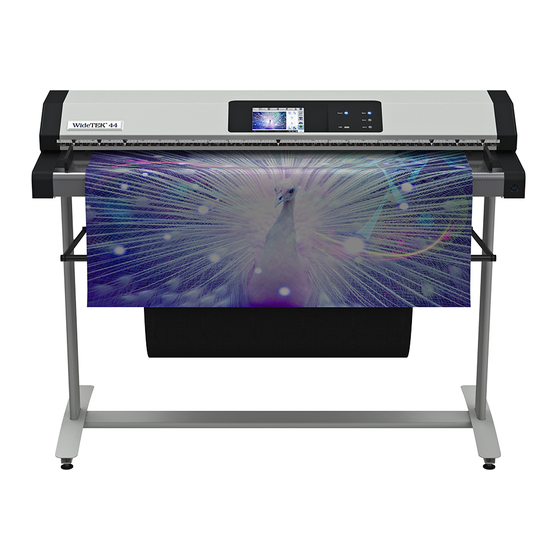
Description WideTEK 44 Overview Name Document transport Touchscreen Power button Main switch Transport guides The WideTEK 44 scanner can be extended to a WideTEK 48 by purchasing a software option. -
Page 13: Widetek 48 Overview
Description WideTEK 48 Overview Name Document transport Touchscreen Power button Main switch Transport guides... -
Page 14: Rear View
Description Rear View The following diagram shows the rear view of the WideTEK® 36 model. Name USB connector Network connector HDMI connector 24 V DC connector for external power supply Foot switch connector Recovery key connector... -
Page 15: Setup Menu Overview Screen
Description Setup Menu Overview Screen Name Buttons and parameters Menu name Display the online help Button to leave the setup menu to the start screen Button to drive the document forward in the scanner Button to drive the document backward in the scanner (rewind). Firmware version IP address Serial number... -
Page 16: Rating Plate
Description Rating Plate The rating plate is attached to the back of the scanner. The following figure shows the WideTEK® 36 rating plate. - Page 17 Description The following figure shows the WideTEK® 44 rating plate.
- Page 18 Description The following figure shows the WideTEK® 48 rating plate.
-
Page 19: Prepare For Setup
Prepare for Setup Prepare for Setup Connect the Power Supply WARNING Risk of electric shock due to incorrect connection. Ensure that the power receptacle intended for the connection is properly grounded. Ensure that the power receptacle intended for the connection of the scanner is properly fused. -
Page 20: Positioning The Scanner On The Optional Floor Stand
Prepare for Setup To establish the network connection, proceed as follows: Connect one plug of the enclosed network cable to the network connector socket on the back of the scanner. Connect the second plug to the network socket of an existing network. Positioning the Scanner on the Optional Floor Stand CAUTION The scanner weighs between 41 kg and 53 kg, depending... -
Page 21: Connect The Optional Monitor
Prepare for Setup Connect the Optional Monitor CAUTION Incorrect laying of the connection cables can cause tripping. Fractures, contusions and bruises can be the result. Place the connecting cables so that nobody can trip over them. To connect the optional monitor, proceed as follows: ... -
Page 22: Connect The Optional Touchscreen
Prepare for Setup Connect the Optional Touchscreen CAUTION Incorrect laying of the connection cables can cause tripping. Fractures, contusions and bruises can be the result. Place the connecting cables so that nobody can trip over them. To connect the optional touchscreen, proceed as follows: ... -
Page 23: Switch On The Scanner
Prepare for Setup Switch On the Scanner To switch on the scanner, proceed as follows: Press the MAIN SWITCH (1) to the "I" position. The following diagram shows the scanner model WideTEK® 36. The scanner is in standby mode. The power switch is illuminated in red. - Page 24 Prepare for Setup To start the scanner from standby mode, proceed as follows: Press the red illuminated power button. The power button lights up in blue. The scanner performs a system test. After a short wait, the "Start screen" is displayed in English.
-
Page 25: Switch Off The Scanner
Prepare for Setup Switch Off the Scanner To switch the scanner to standby mode after performing the setup, proceed as follows: On the "Start screen" screen tap on SHUTDOWN (1). Confirm with YES. The scanner shuts down. This process can take up to 40 seconds. The power button lights up red. - Page 26 Prepare for Setup Alternatively, switch the scanner into the standby mode as follows: Press the blue illuminated power button and hold it for six seconds. The scanner shuts down. This process can take up to 40 seconds. The power button lights up red. The scanner is in standby mode. To switch off the scanner for longer periods, proceed as follows: ...
-
Page 27: Perform Setup
Perform Setup Perform Setup Change the Menu Language To change the menu language, proceed as follows: Tap the LANGUAGE (1) button. - Page 28 Perform Setup A window for selecting the language appears. To display more languages, slide the scroll bar (1) downward. Tap the desired language. The window for selecting the language is closed. The "Start screen" is displayed.
-
Page 29: Activate The Setup Menu
Perform Setup Activate the Setup Menu To activate the setup menu, you have to log in on the scanner. Proceed as follows: Tap the GEAR SYMBOL (1). - Page 30 Perform Setup The login window appears. In the login window, enter the login credentials. To enter the credentials, tap with your finger on the corresponding input field. The screen keyboard is displayed. Enter the word "Poweruser" in the fields "Username" (1) and "Password"...
- Page 31 Perform Setup To complete the log in, press OK (1).
- Page 32 Perform Setup The "Setup Menu" screen is displayed. White Balance: Display the "White Balance" submenu Test Suite: Display the "Test Suite" submenu IP Address: Display the "IP Address" submenu User Settings: Display the "User Settings" submenu Time and Date: Display the "Time and Date" submenu Touchscreen Test: Display the "Touchscreen Test"...
-
Page 33: Perform White Balance
Perform Setup Perform White Balance On the "Setup Menu" screen, tap on WHITE BALANCE (1). - Page 34 Perform Setup The "White Balance" screen is displayed. Calibrate: Start white balance Delete White Delete existing white balance data Balance Data: The white balance is used to ensure the quality of the scan results. The white balance will be carried out using a test target. The test targets are marked as follows: ...
- Page 35 Perform Setup Before beginning the white balance procedure, remove the transport guides. To remove the transport guides, proceed as follows: Lift the transport guides (1) approximately 5 mm (1.). Pull the transport guides (1) inwards (2.). The following diagram shows the scanner model WideTEK® 36.
- Page 36 Perform Setup ATTENTION! Impairment of the scan quality can occur if an improper test target for the white balance is used. Make sure that the test target is free from wrinkles, discolorations, cracks or other damage. Store the test target for the white balance in a safe place protected from daylight.
- Page 37 Perform Setup Tap on CALIBRATE (1).
- Page 38 Perform Setup Tap on NEXT STEP (1).
- Page 39 Perform Setup The white balance starts and the calibration is performed. During the white balance, a rotating icon appears. The test target is transported forward and returned. The entire white balance sequence takes about 50 seconds. Then, the white balance result is displayed as shown on the example below.
- Page 40 Perform Setup To perform the white balance again, tap NEW VALUES (2). To return to the previous submenu, tap BACK (1). To return to the "Start screen", tap EXIT (3).
- Page 41 Perform Setup To delete the stored data of the white balance calibration, tap DELETE WHITE BALANCE DATA (2). After deleting the stored data, run the white balance again, as described. If problems arise during the white balance calibration, contact Image Access technical support, see section Technical Support starting at page ...
-
Page 42: Assign The Ip Address
Perform Setup Assign the IP Address Manually Assign the IP Address To manually assign the IP address, proceed as follows: On the "Setup Menu" screen, tap on IP Address (1). - Page 43 Perform Setup The "IP Address" screen is displayed. Set network Accept the network settings provided settings: Reset to Factory: Reset to factory settings IP Address: Input field for the IP address Subnet Mask: Input field for data on the subnet mask Gateway: Input field for the gateway address IP Configuration...
- Page 44 Perform Setup Tap the "IP Address" (1) field.
- Page 45 Perform Setup The "IP Address" window is displayed. Enter the IP address (1).
- Page 46 Perform Setup To delete a digit, move the cursor to the right, behind the digit to be deleted and tap DEL (1).
- Page 47 Perform Setup The arrow keys left (1) and right (2) next to the number "0" move the cursor within the chosen row. To complete the entry, press OK (3). Perform the settings for gateway and subnet mask in the same way.
- Page 48 Perform Setup To save the network settings, tap SET NETWORK SETTINGS (2). To return to the previous submenu, tap BACK (1). To return to the "Start screen", tap EXIT (3).
- Page 49 Perform Setup Automatically Assign the IP Address To automatically assign the IP address, proceed as follows: On the "Setup Menu" screen, tap on IP Address (1).
- Page 50 Perform Setup In the selection menu "IP Configuration Method", select the "DHCP" (3) entry. To return to the previous submenu, tap BACK (1). To return to the "Start screen", tap EXIT (2).
-
Page 51: Modify User Settings
Perform Setup Modify User Settings On the "Setup Menu" screen, tap on USER SETTINGS (1). - Page 52 Perform Setup The "User Settings" screen is displayed. Configure GUI Open the submenu for setting the application in Selection: the start screen Default: The scanner default settings will be established again Language: Select language Display standby Define the period of inactivity, until an optional after: external monitor and the touchscreen switch to the standby mode...
- Page 53 Perform Setup Select Language To select the language, proceed as follows: Tap the on the selection arrow of the selection menu "Language" to display the list of languages. Tap the desired language (2). To return to the previous submenu, tap BACK (1). ...
- Page 54 Perform Setup Set Standby Times To set the standby times, proceed as follows: Tap the selection arrow of the selection menu. Tap on the desired entry (2). Perform the settings for the screen saver and the device standby in the same way.
- Page 55 Perform Setup Adjust Volume To adjust the volume of the system sounds of the scanner, proceed as follows: Slide the volume control (4) to the desired position. In the "0%" setting, system sounds are not audible. In the "100%" setting the maximum volume is reached.
- Page 56 Perform Setup Configuring the GUI Selection Tap the "User Settings" screen on CONFIGURE GUI SELECTION (1).
- Page 57 Perform Setup The "Configure GUI Selection" screen is displayed. This menu displays the "EasyScan" and "ScanWizard" applications, which are available as a standard selection. If, after system start you want to display only one of the applications, proceed as follows: ...
- Page 58 Perform Setup By default, job mode is defined (disable the checkbox "Single mode enabled"). To start the application in standalone mode, check the checkbox "Single mode enabled" (2). To return to the previous submenu, tap BACK (1). To return to the "Start screen", tap EXIT (3).
-
Page 59: Set The Time And Date
Perform Setup Set the Time and Date On the "Setup Menu" screen, tap on TIME and DATE (1). - Page 60 Perform Setup The screen "Time and Date" appears. Enter new time: Enter hours and minutes with the arrow keys Enter new date: Open a calendar to set the date Store time and Accept the set values date: Time Zone: Select a time zone...
- Page 61 Perform Setup To set the time, proceed as follows: Tap the "Enter new time" field. To set the time later, tap the up arrow (2). To set the time earlier, tap the down arrow (2). To save the modified time, click STORE TIME AND DATE (3). ...
- Page 62 Perform Setup To set the date, proceed as follows: Tap the "Enter new date" field. A calendar (3) is displayed. Select the appropriate date in the calendar (3). To set the month and year, tap the arrow keys (2, 4) at the top of the calendar.
- Page 63 Perform Setup To select the time zone, tap the selection arrow (4). A selection list with available time zones is displayed. Select the appropriate time zone. To save the time zone, click STORE TIME AND DATE (2). ...
-
Page 64: Perform Test Suite
Perform Setup Perform Test Suite On the "Setup Menu" screen, tap on TEST SUITE (1). - Page 65 Perform Setup The "Test Suite" screen is displayed. Information about Display the current values for: the mainboard: Temperature of PCB and CPU cores, fan speed, PCB voltages Information about Inputs will always appear green the inputs: Information on end When the end position switches, foot switch or position switches, the power button is pressed, the display changes foot switch and...
- Page 66 Perform Setup Test the LED Lamps Functionality To check whether the LED lamps work properly, select from the "Lamp" menu the entry "Lamp On" (3). The LED lamps are illuminated. To return to the previous submenu, tap BACK (1). ...
- Page 67 Perform Setup Test the Optional Foot Switch Functionality To check whether the actuation of the foot switch is detected by the system, press down the connected foot switch. The field "Foot Switch" (3) is shown in red. Pressing the foot switch is detected by the system.
- Page 68 Perform Setup Test the Power Button Functionality To check whether pressing the power button is recognized by the system, press and hold the power button for one or two seconds. The field "Start Button" (3) is shown in red. Pressing the power button is detected by the system.
-
Page 69: Touchscreen Test
Perform Setup Touchscreen Test To check the functionality of the touchscreen when touched, proceed as follows: On the "Setup Menu" screen tap on TOUCHSCREEN TEST (1). - Page 70 Perform Setup The "Touchscreen test" screen is displayed. Tap with your finger on the corresponding screen (2). The cross-lines must occupy the same position as the finger. To end the "Touchscreen test", tap STOP TOUCHSCREEN TEST (1). The "Start screen" is displayed.
-
Page 71: Technical Specifications
Technical Specifications Technical Specifications WideTEK® 36/44/48 Scanner Specification Optical System WideTEK® 36 Maximum document size 970 mm / 38,2 inch Scan width 915 mm / 36 inch Scanner resolution 1200 × 1200 dpi (optional 9600 × 9600 dpi interpolated) Optical resolution 1200 ×... - Page 72 Technical Specifications Optical System WideTEK® 44 Maximum document size 1300 mm / 51.2 inch Scan width max. 1118 mm / 44 inch Scanner resolution 1200 × 1200 dpi (optional 9600 × 9600 dpi interpolated) Optical resolution 1200 × 600 dpi Pixel size 9,3 ×...
- Page 73 Technical Specifications Optical System WideTEK® 48 Maximum document size 1270 mm / 50 inch Scan width max. 1219 mm / 48 inch Scanner resolution 1200 × 1200 dpi (optional 9600 × 9600 dpi interpolated) Optical resolution 1200 × 600 dpi Pixel size 9,3 ×...
-
Page 74: Ambient Conditions
Technical Specifications Ambient Conditions Ambient temperature during +5 to +40 °C operation Storage temperature 0 to +60 °C Relative humidity 20 to 80% (non-condensing) Noise development ≤ 35 dB(A) (Scanning) ≤ 25 dB(A) (Standby) Electrical Data External Power Supply Input voltage 100–240 Vac Frequency 47–63 Hz... -
Page 75: Document Specifications
Technical Specifications Power consumption WideTEK® 44/48 Sleep mode ≤ 0,5 W Standby mode ca. 6,5 W Ready to scan < 60 W Scanning < 120 W Document specifications Document length up to 500 m / 20.000 inch Paper weight Document thickness 2,5 mm / 0,1 inch max. -
Page 76: Dimensions And Weight Widetek® 44/48
Technical Specifications Dimensions and Weight WideTEK® 44/48 Scanner (H x W x D) 228 x 1425 x 507 mm Scanner with floor stand 1070 x 1425 x 507 mm (H x W x D) Scanner weight 53 kg Floor stand weight / including the 20/22 kg paper catch Transport box (H x W x D)
Need help?
Do you have a question about the WideTEK 36 and is the answer not in the manual?
Questions and answers