Sign In
Upload
Manuals
Brands
Image Access Manuals
Scanner
WideTEK 36
Image Access WideTEK 36 Manuals
Manuals and User Guides for Image Access WideTEK 36. We have
7
Image Access WideTEK 36 manuals available for free PDF download: Setup Manual, Operation Manual, Instruction Manual, Setup Instructions, Setup And Assembly Manual
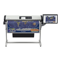
Image Access WideTEK 36 Setup Manual (155 pages)
Brand:
Image Access
| Category:
Scanner
| Size: 15 MB
Table of Contents
Table of Contents
7
Introduction
4
About the Manual
5
Version History
6
Table of Contents
7
Table of Contents
13
A Safety Notes
18
Safety Notes
18
Marking of Safety Notes
18
Certification
18
Safety Precautions
19
A.3 Safety Precautions
19
In General
20
Maintenance
20
Surfaces
20
Touchscreen
20
Repair
20
A.4 in General
20
Device Location
21
Picture 1: Minimum Distances
21
A.7 Device Location
21
B Transport Box
22
Widetek ® 36
22
Picture 2: Widetek ® 36 Transport Box
22
Picture 3: Transport Box Opened
22
Picture 4: Scanner with Accessories and Floor Stand
23
Picture 5: Widetek 48 and Accessories in Transport Box
24
Widetek ® 48
24
Keeping the Transport Box for Later Use
25
Picture 6: Transport Box Elements Ready to Store
25
Scanner Dimensions
26
Without Floor Stand
26
With Floor Stand
26
B.4 Scanner Dimensions
26
Picture 7: Widetek 36 Front View
26
Picture 8: Scanner in Combination with Floor Stand and Monitor
26
B.5 Connectors
27
Connectors
27
Main Power Switch
27
Picture 10: USB Connector
27
Picture 9: Main Power Switch
27
USB Connector
27
Back Side Left
28
Back Side Right
28
Picture 11: Connectors at Left Back Side
28
Picture 12: Connectors at Left Back Side
28
Picture 13: Floor Stand Box Opened
29
Picture 14: Assembling Material
29
Picture 15: Parts of Floor Stand
30
C.1.2 Dimensions of Floor Stand Parts
31
C.1.3 List of Assembling Material and Tools
32
Picture 16: Assembly Steps
33
Picture 17: Lower Crossbeam Combined with Foot and Vertical Leg
33
C.2 Assembling the Floor Stand
33
Picture 18: Drawing "Detail C
34
Picture 19: Inserting Screws with Washer
34
Picture 20: Bottom and Side Components Assembled
34
Picture 21: Upper Longitudinal Foot on Vertical Leg
35
Picture 22: Upper Crossbeam Inserted
35
Picture 23: Inserting the Rod
36
Picture 24: Floor Stand Complete
36
C.3 Securing the Scanner at the Floor Stand
37
Picture 25: Parts of Monitor Mount
38
Picture 26: Base Plate with Marking „TOP
38
C.4 Monitor Mount
38
Picture 27: Assembling the Base Plate to the Vertical Leg
39
Picture 28: Base Plate Fastened with Hexagon Head Screws
39
C.4.2 Assembling the Monitor Mount
39
Picture 29: First Step Monitor Mount on Base Plate
40
Picture 30: Final Position of Monitor Mount at Base Plate
40
C.4.2.2 Monitor Mount Fastening on Base Plate
40
Picture 31: Fixing the Monitor Mount
41
Picture 32: Floor Stand with Monitor Mount
41
Picture 33: Viewer & Job Control Screen
42
Picture 34: Setup Menu Items
42
D Setup and Adjustments
42
Picture 35: Setup Menu, Start Screen
43
D.1 White Balance
43
Picture 36: IP Address Mask
44
D.2 IP Address
44
Picture 37: User Settings Menu
45
D.3 User Settings
45
Picture 38: Selectable Presets
47
Picture 39: Presets Selection Screen
47
D.3.1 Change GUI
47
D.3.3 Show Application Menu
48
Picture 40: Time and Date
49
Picture 41: Testsuite Screen
50
D.5 Testsuite
50
Picture 42: User Preset Screen
51
D.6 User Preset
51
Picture 43: Keyboard on the Touchscreen
52
D.6.1 Preset Selection – Create Preset
52
Picture 44: Selecting the Preset Content
53
D.6.2 Preset Selection – Configure Preset
53
D.6.2.2 Saving the Preset Functions
54
D.6.3 Preset Selection – Delete Preset
55
Picture 45: Scan2Net Start Screen
56
E Poweruser Level
56
Picture 46: Login Level Screen
57
E.1 Setup Menu
57
Picture 47: Main Menu Poweruser Level
58
E.2 Main Menu
58
E.2.1.1 Navigating through the Menus
59
Picture 48: Device Info
60
Picture 49: Operation Info
60
E.3 Device Information
60
Picture 50: Language Selector
61
E.4 Base Settings
61
Picture 51: File Name
62
Picture 52: List of Wildcard Characters
62
E.4.1.2 File Name
62
Picture 53: Power Saving
63
E.4.1.3 Power Saving
63
Picture 54: Transport Speeds
64
E.4.1.4 Transport Speed
64
Picture 55: Volume Level
65
E.4.1.5 Volume
65
Picture 56: Start Button Timeout
66
Picture 57: Display Parameters
67
E.4.1.7 Display
67
Picture 58: Guide Plate Middle
68
Picture 59: List of Available Erasing Methods
69
E.4.1.9 Secure File Erasing
69
Picture 60: Kiosk App Selection
70
E.4.1.10 Kiosk App
70
Picture 61: Show Warnings Selector
71
Picture 62: Validate Certificates Selector
71
E.4.1.11 Show Warnings
71
Picture 63: IP Configuration Method
72
E.4.2 Network Configuration
72
Picture 64: Settings of Ipv4 (Network Interface 0)
73
Picture 65: Settings of Ipv4 (Network Interface 1)
74
Picture 66: Domain Name Server Parameters
76
Picture 67: SMB Settings
77
E.4.2.5 SMB Settings
77
Picture 68: Firewall Settings
78
E.4.2.6 Firewall
78
Picture 69: Wireless LAN Basic Settings
79
E.4.2.7 Wireless LAN (Basic Settings)
79
Picture 70: Wireless LAN (LAN Interface)
80
Picture 71: Wireless LAN (Security)
81
Picture 72: Wireless LAN (DHCP)
82
E.4.3 Adjust Time & Date
83
Picture 73: Time Format
84
E.4.3.1 Time Format
84
Picture 74: Time Zone Screen
85
E.4.3.2 Time Zone
85
Picture 75: Manual Adjustment
86
E.4.3.3 Manual Adjustment
86
Picture 76: NTP Server Setting
87
E.4.3.4 NTP Server
87
Picture 77: Set Volume
88
E.4.4 Sound System
88
Picture 78: Sound Files List
89
Picture 79: Upload New Sound Files
89
E.4.4.2 Sound Files
89
Picture 80: Link Events List
90
E.4.4.3 Link Events
90
Picture 81: Options List
91
E.4.5 Installed Options
91
Picture 82: Server Certificate Information
92
E.4.6 Certificates
92
Picture 83: Selector for Name, Privacy and Owner
93
E.4.7 Templates
93
Picture 84: Excluded Wildcard Characters
94
E.4.7.1 Exclusion of Wildcard Characters for Jobmode Scanning
94
Picture 85: Template List for Remote Printer
95
E.4.7.2 Remote Printer
95
Picture 86: Remote Printer Parameters
96
Picture 87: Template List for FTP Server
100
Picture 88: FTP Server Parameters
100
E.4.7.3 FTP Server
100
Picture 89: Template List for Mail Server
102
E.4.7.4 Mail Server
102
Picture 90: Mail Server Parameters
103
Picture 91: Template List for SMB Configuration
105
Picture 92: SMB Configuration Parameters
105
E.4.7.5 SMB Configuration
105
Picture 93: Template List for Web Service Configuration
107
Picture 94: Web Service Parameters
108
Picture 95: Template List for USB Device
111
Picture 96: USB Device Parameters
111
E.4.7.7 USB Device Configuration
111
Picture 97: Template List for Metadata
113
E.4.7.8 Metadata
113
Picture 98: Metadata Parameters
114
Picture 99: Template List for PDF Document
115
E.4.7.9 PDF Document
115
Picture 100: PDF Document Parameters
116
Picture 101: LDAP Directory Service Templates
117
Picture 102: LDAP Directory Parameters
118
Picture 103: Update Scanner Firmware
119
Picture 104: Scanner Profile
121
E.5.2 ICC Profiles
121
Picture 105: Available Color Spaces
122
Picture 106: ICC Profile Information
122
Picture 107: Printer Profile Status Message
123
Picture 108: Printer Profiles
123
E.5.2.2 Printer Profiles
123
Picture 109: ICC Profile Information
124
Picture 110: Touchscreen Screensaver
125
E.5.3 Touchscreen / Desktop
125
Picture 111: Desktop Screensaver List
126
Picture 112: Preview of Desktop Image
126
E.5.3.2 Desktop Screen
126
Picture 113: Lock Screen Screensaver List
127
E.5.3.3 Lock Screen
127
Picture 114: Java Apps
128
E.5.4 Java Apps
128
Picture 115: Status Message
129
Picture 116: PDF Cover Sheet
129
Picture 117: Adjustment Main Screen
130
E.6 Adjustments & Support
130
Picture 118: White Reference Target on Document Table
131
E.6.1.1 White Balance
131
Picture 119: Streak Compensation
132
E.6.1.2 Streak Compensation
132
Picture 120: Brightness Correction Factor List
133
E.6.1.4 Brightness Correction
133
Picture 121: Transport Speed Fine Tuning
134
E.6.1.5 Transport Speed
134
Picture 122: Stitching Start Screen
135
Picture 123: Display of Cut Outs (WT36)
135
E.6.1.6 Stitching
135
Picture 124: Display of Cut Outs (WT48)
136
Picture 125: Log Files Overview, Software Version 6.X
137
E.6.2 Log Files
137
Picture 126: Selection Box at the Bottom of the Screen
138
E.6.2.2 Stitching Log Enabled
138
Picture 127: Available Test Target
139
Picture 128: Example for Test Target Position
139
E.6.3 Scan Test Targets
139
Picture 129: Request after Scanning the Test Target
140
Picture 130: UTT Test Target on Glass Plate
141
Picture 131: IT8 Test Target on Glass Plate
141
E.6.3.2 Scan UTT Test Target
141
Picture 132: Hardware Test Suite Start Screen
142
Picture 133: Network Analyzer Menu Items
142
Picture 134: Network Analyzing Parameters
143
Picture 135: Measured Time
144
Picture 136: Packet Statistics Values
144
Picture 137:WLAN Module Successful Installed
145
E.7 Additional Hardware
145
Picture 138: Wake up Remote Host
146
E.8 Administrative Settings
146
Picture 139: Change Password Menu
147
E.8.2 Change Password
147
Picture 140: Small Window at Bottom Line with Inquiry for Action
148
E.8.3 Backup Settings
148
Picture 141: Restore Setting from ZIP File
149
Picture 142: Message after Restoring
149
E.8.4 Restore Settings
149
Picture 143: Enter Password to Lock the User Interface
150
E.8.5 Lock Web App
150
E.9 Resets & Default Values
151
F.1 Scanner Specifications
152
F.2 Document Specification
153
F.3 Electrical Specifications
154
F.4 Dimensions and Weight
155
Advertisement
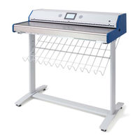
Image Access WideTEK 36 Instruction Manual (124 pages)
WideTEK 36
Brand:
Image Access
| Category:
Scanner
| Size: 9 MB
Table of Contents
Introduction
4
About this Manual
5
Version History
6
Table of Contents
7
About this Manual
7
Version History
7
Technical Data
10
Manual Page
11
Manual Page
13
A Hardware
14
Safety Notes
14
Marking of Safety Notes
14
Certification
14
General Notice
14
Safety Precautions
15
A.4 Safety Precautions
15
Connecting to the Power Source
16
Device Location
17
Picture 1: Minimum Distances to the Scanner
17
A.6 Device Location
17
Maintenance
18
Touchscreen
18
Surfaces
18
Glass Plate
18
Repair
18
A.7 Maintenance
18
Content on Delivery
19
Picture 2: Transport Box Opened
19
A.9 Content on Delivery
19
Connectors on the Scanner
20
Picture 3: Connectors at Widetek 36
20
A.11 Adjusting the Middle Guide Plate
21
Picture 4: Middle Guide Plate
21
Picture 5: allen Head Screw in Slot Hole
22
Picture 6: Removing the Middle Guide Plate
22
Picture 7: Self Locking Nut on the Bottom Side of Middle Guide Plate
23
Paper Transport Wings
24
Picture 8: Black Paper Transport Wing
24
Picture 9: Snap Lock on Left Side of the Housing
24
How to Insert the Paper Transport Wings
25
Picture 10: Bending the Paper Transport Wing
25
Picture 11: Inserting at the Front
25
Picture 12: Position of Paper Transport Wings
26
Picture 13: Position for Light Paper Weights
26
Position of the Paper Transport Wings
26
Scanning Documents on Light, Thin Paper Material
26
Picture 14: Inserting at the Back
27
Picture 15: Position for Normal and High Paper Weights
27
Scanning Documents on Normal or Heavier Paper
27
Connecting an External Monitor
28
Picture 16: Position of VGA Connector
28
Picture 17: VGA Connector Beside Gap
28
Picture 18: Guiding into the Scanner
28
Picture 19: Guiding the Cable to the Connector
29
Picture 20: VGA Connector Inserted
29
Powering up the Widetek 36
30
Widetek 36 Touch Panel
30
Starting the Widetek 36 from Stand-By Mode
30
Picture 21: Start Menu Screen
30
Turning-Off the Widetek 36
31
The Help Function
31
Picture 22: Touch Panel While Shut down in Progress
31
Navigating through the Screens
32
How to Enter or Change Values
32
Picture 23: Keyboard with Capital Letters
32
Picture 24: Keyboard with Lower Case Letters
32
Self Test Mode
33
Picture 25: Self Test 1
33
Picture 26: Self Test 2
33
A.17.1 IP Address
34
IP Address
34
Picture 27: Network Setup
34
Picture 28: Numeric Key Pad
34
Picture 29: Confirm Changes
34
A.17.2 White Balance
35
Picture 30: Insert Control Sheet
35
Picture 31: Results of White Balance
35
White Balance
35
A.17.5 Touch Adjust
36
Picture 32: Testing the Touch Screen
36
Manual Page
37
Picture 33: Stitch Test Screen
37
A.17.9 Sensor Test
38
Picture 34: Sensor Status
38
Picture 35: Start Menu Screen
39
Picture 36: Document Transport Controls
39
A.19 Output Control Screens
40
Picture 37: Output Control 1
40
Picture 38: Viewer Control
40
A.19.1.2 Email Address
41
Picture 39: E-Mail Address Parameters
41
A.19.1.3 FTP Server
42
Picture 40: Ftp Server 1
42
Picture 41: Ftp Server 2
43
A.19.1.4 Windows Network
44
Picture 42: Network Parameters
44
Picture 43: Input a Network Address
44
A.19.2 Output Control 2
45
Picture 44: Output Control 2
45
Picture 45: System Events and Sound Files
45
A.20 Image Control Screen
46
Picture 46: Image Control 1
46
A.20.1.4 Sharpness
47
A.20.2 Image Control 2
48
Picture 47: Image Control 2
48
A.20.2.4 Stitching
49
A.20.3 Image Control 3
50
Picture 48: Image Control 3
50
A.21 Format Control Screen
51
Picture 49: Format Control 1
51
A.21.2 Format Control 2
52
Picture 50: Format Control 2
52
A.21.3 Format Control 3
53
Picture 51: Format Control 3
53
A.22 File Control Screen
54
Picture 52: File Control
54
A.22.2 Tiff
55
A.22.4 Pdf
56
A.23 Transport Control Screen
57
Picture 53: Transport Control
57
A.23.4 Feeder Delay
58
A.24 Job
59
Picture 54: List of Available Jobs
59
Picture 55: Keyboard of Input Screen
59
Picture 56: Creating a Job
60
Picture 57: Entering the Password
60
Picture 58: Number of Password Elements
60
A.24.2 Selecting a Job
61
Picture 59: Selecting a Job from the List
61
Picture 60: Request for Password
61
A.24.3 Deleting a Job
62
Picture 61: Confirming to Delete the Job
62
Picture 62: Enter Password to Delete Job
62
A.25 Software Option: Scan2Vga
63
Picture 63: Touchpanel after Scanning
63
B Software
64
Picture 64: Start Screen
64
B.2 the Main Screen
65
Picture 65: Main Screen
65
Picture 66: Shutdown Confirmation
66
B.2.1 the Options Screen
67
Picture 67: Options Screen
67
B.2.2 the Properties Screen
69
Picture 68: Properties Screen
69
Picture 69: 24Bit Color, File Format: PNM
70
Picture 70: Binary, File Format: TIFF with G4 Compression
70
Picture 71: Format List
72
Picture 72: Additional Margin/Auto Density Slider
72
Picture 73: Set Deskew Angle
73
Picture 74: Document Edges
73
B.2.3 the Camera Screen
74
Picture 75: Camera Screen
74
Picture 76: Exposure Control Slider
75
B.2.3.1 Threshold Dynamic / Threshold Fixed
76
Picture 77: Threshold Method Selector
76
Picture 78: Despeckle Function
76
B.2.4 the Settings Screen
77
Picture 79: Settings Screen
77
Table of Pictures, Part 3
78
Picture 80: Available Skins
78
Picture 81: Scan Status Window
78
B.2.5 the Format Screen
79
Picture 82: Format Screen
79
Picture 83: Rectangle Dragged with Mouse
80
Picture 84: "Zoom In" Result
80
Picture 85: List of Available Clip Size Formats
80
B.3 Output Options
81
Picture 86: Output Options
81
Picture 87: Output Option Save
82
Picture 88: Example for File Name
82
Picture 89: Output Option Show
83
Picture 90: Output Options in Scan Window
83
Picture 91: Output Option Multipage
84
Picture 92: Pop-Up Window to Select Images for the "Container
85
Picture 93: Output Option Print
86
Picture 94: Available List of Printers for Option Print
86
Picture 95: Output Option Copy
87
B.3.5.2 Printing Enhancement
89
B.3.5.3 Accounting
90
B.3.5.4 Extended Print Parameters with Ipf Option Installed
91
B.3.5.5 Printing Enhancements with Ipf Option Installed
92
Picture 96: Output Option FTP Upload
93
Picture 97: Output Option Mail
95
Manual Page
97
Picture 98: Parameters for Transaction Mode "Interactive
97
Picture 99: Recipient Address List Opened
97
Picture 100: Output Option Network
98
B.3.8.1 SMB Configuration
99
Picture 101: Output Option Web
100
B.3.9.1 Web Service Configuration
101
Picture 102: Output Option USB
102
Picture 103: USB Stick Inserted in USB Connector
102
B.3.10.1 USB Storage Device
103
B.4 Information
104
Picture 104: Information
104
B.5 the Setup Screen
105
Picture 105: Login Screen
105
B.5.2 Access Level User
106
Picture 106: User Screen
106
Picture 107: Device Info Screen
107
Picture 108: Operation Info Screen
108
B.5.2.3 User Settings Screen
109
Picture 109: Available User Settings
109
B.5.2.3.1 Language Selector
110
Picture 110: Language Selector Screen
110
B.5.2.3.2 Power Saving
111
Picture 111: List of Power down Times
111
B.5.2.3.3 Volume
112
Picture 112: Volume Level
112
B.5.2.3.4 Foot Pedal
113
Picture 113: Foot Pedal Settings
113
Picture 114: Splitting Start Page
114
Picture 115: Guide Plate Middle
115
C Tests and Troubleshooting
116
C.2 Error Codes
117
C.3 Warnings
119
D Technical Data
120
D.3 Electrical Specifications
121
D.5 CE Declaration of Conformity
122
D.6 FCC Declaration of Conformity
123
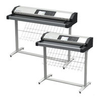
Image Access WideTEK 36 Operation Manual (129 pages)
Brand:
Image Access
| Category:
Scanner
| Size: 11 MB
Table of Contents
Introduction
4
About this Manual
5
Version History
6
Table of Contents
7
A Safety Notes
16
General Notice
16
Safety Notes
16
Marking of Safety Notes
16
Certification
16
Safety Precautions
17
A.4 Safety Precautions
17
B Hardware
18
Content on Delivery
18
Picture 2: Transport Box Opened
19
Keeping the Transport Box for Later Use
20
Device Overview
21
Front Side Elements
21
B.2 Device Overview
21
Rear Side Connectors
22
Main Power Switch
22
Connecting to the Power Source
23
Powering up the Scanner
24
Starting the Scanner from Standby Mode
24
Switching the Scanner to Standby Mode
24
Device Location
25
B.5 Device Location
25
Maintenance
26
Touchscreen
26
Surfaces
26
Glass Plate
26
Repair
26
B.6 Maintenance
26
Table of Content, Part 2
27
C Touchscreen Operation
27
C.1 Select Application Screen
28
C.1.1 Document Transport Settings
29
C.1.1.4 Scan Mode
30
C.1.1.5 Document Output
31
C.2 Scanwizard Application
32
C.2.1 Size
34
C.2.1.2 Mirror
36
C.2.2 Quality
37
C.2.2.2 Color Space
38
C.2.2.5 Dpi
39
C.2.2.7 Illumination
40
C.2.3 Enhancement
41
C.2.3.4 Exposure
42
C.2.3.5 Threshold
43
C.2.4 Transport
44
C.2.4.3 Transport Speed
45
C.2.5 Transfer
46
C.2.5.1 Modifying an Entry of the Transfer Target
47
C.2.5.2 Usb
48
C.2.5.3 Smb
49
C.2.5.4 Ftp
50
C.2.5.5 Default
51
C.2.5.6 Mail
52
C.2.5.7 Remote Printer
53
C.2.5.8 File Format
54
C.2.5.10 File Type
55
C.2.5.11 PDF Document
56
C.2.5.12 Embedded Metadata
57
C.2.6 Job Mode in Scanwizard Application
58
Picture 50: Startscreen Job Mode
59
C.2.6.1 Job Mode, Move Image
60
C.2.6.4 Job Mode, Deleting an Image
61
C.2.7 Zonal OCR
62
Picture 54: Resulting Text of the OCR Process
63
C.2.8 Return to Select Application Screen
64
C.3 Scan2Net® Start Screen
65
C.3.1 Control Fields of the Touchscreen
66
C.4 Touchscreen – Document Source
67
C.4.1 Dpi
68
C.4.2 Splitting
69
C.4.3 Scan Mode
70
C.4.4 Auto Density
71
C.4.5 Exposure
72
Picture 66: Sliders to Set the Values
73
C.4.6 Format
74
C.4.6.2 Auto
75
C.4.6.4 Din
76
C.4.7 Transport Speed
77
C.4.8 Color Space
78
C.4.9 Additional Margin
79
C.4.10 Stitching
80
C.5 Touchscreen – Image Quality
81
C.5.1 Color Mode
82
C.5.2.2 Tiff
83
C.5.3 Brightness
84
C.5.6 Image Rotation
85
C.6 Touchscreen – Viewer&Job Control
86
C.6.1 Zonal OCR
88
Picture 93: Rectangle Defines the Area for OCR Function
89
Picture 95: Selected Area Magnified
90
C.6.2 Job Mode
91
Picture 99: Disclaimer When Staring the Job Mode
92
C.6.2.1 Navigating through the List of Images
93
C.6.2.2 Moving an Image to Another Position
94
C.6.2.6 Finalizing the Job Mode
95
C.7 Touchscreen – Send to
96
C.7.1 Changing a File Name or Other Entries
97
C.7.2 USB Options
98
C.7.3 Copy Options
99
C.7.4 FTP Options
100
C.7.5 Network Options
101
C.7.6 Mail Options
102
C.7.6.1 Transaction Modes
103
Table of Content, Part 5
104
D the User Interface Scanwizard Web
104
D.1 the Scanwizard User Interface
105
Picture 117: Online Help
106
D.2 Information
107
E the Setup Level
108
E.1 Access Level User
109
E.1.1 Device Info
110
E.1.2 Operation Info
111
E.2 User Settings
112
E.2.1.1 Language Selector
113
E.2.1.2 File Name
114
E.2.1.3 Power Saving
115
E.2.1.4 Transport Speed
116
E.2.1.5 Volume
117
E.2.1.6 Guide Plate Middle
118
E.2.1.7 Ocr
119
F Tests and Troubleshooting
120
G Technical Data
121
G.2 Electrical Specifications
124
G.3 Document Specification
125
G.5 Dimensions and Weight
126
G.6 CE Declaration of Conformity
127
G.7 FCC Declaration of Conformity
128
Advertisement
Image Access WideTEK 36 Setup And Assembly Manual (69 pages)
Brand:
Image Access
| Category:
Scanner
| Size: 3 MB
Table of Contents
Table of Content, Part
2
Introduction
4
About this Manual
5
Version History
6
Table of Contents
7
A Hardware Setup
14
Content on Delivery
14
Picture 1: Transport Box Opened
14
Contents of Floor Stand Box
15
List of Assembling Material and Tools
15
Picture 2: Floor Stand Box Opened
15
Picture 3: Assembling Material
15
Floor Stand Overview
16
Picture 4: Technical Drawing of Floor Stand
16
Parts of Floor Stand
17
Picture 5: Floor Stand Components
17
Assembling the Floor Stand
18
Picture 6: Side Pillar in Foot Profile
18
Picture 7: Traverse Inserted into Foot Bracket
18
Picture 8: Inserting Screws with Washer
19
Picture 9: Bottom and Side Components Assembled
19
Picture 10: Top Bracket on Vertical Leg
20
Picture 11: Upper Traverse Inserted
20
Combining Floor Stand and Scanner
21
Picture 12: Inserting the Rod
21
Picture 13: Two Persons Lifting the Scanner out of the Transport Box
21
Picture 14: Lift the Scanner to Remove the Foam Rubber Element
22
Picture 15:Removing Foam Rubber Element and Cardboard Element
22
Picture 16: Bottom Side, Front Side Left
23
Picture 17: Bottom Side, Back Side Left
23
Picture 18: Fastening the Scanner Onto the Floor Stand
23
Picture 19: Widetek 36 Placed on Floor Stand, Ready to Use
24
Connecting to the Power Source
25
Connectors at the Scanner
26
Picture 20: Connectors at Widetek 36
26
Powering up the Widetek 36
27
Widetek 36 Touch Panel
27
Starting the Widetek 36 from Stand-By Mode
27
Picture 21: Start Menu Screen
27
Turning-Off the Widetek 36
28
The Help Function
28
Picture 22: Touch Panel While Shut down in Progress
28
Navigating through the Screens
29
How to Enter or Change Values
29
Picture 23: Keyboard with Capital Letters
29
Picture 24: Keyboard with Lower Case Letters
29
IP Address Setup
30
IP Address Setup by Touch Panel
30
Picture 25: Self Test 1 Menu
30
Picture 26: Network Setup
31
Picture 27: Numeric Key Pad
31
Picture 28: Confirm Changes
31
Optical Adjustment
32
White Balance
32
Helpful Information about the White Balance Adjustment
32
Table of Pictures, Part 2
33
Performing the White Balance Adjustment
33
Picture 29: White Balance Screen
33
Picture 30: Progress Indicator
33
Picture 31: White Balance Result
33
B Software Setup
34
Start Screen of the Scan2Net User Interface
34
Picture 32: Start Screen
34
Setup Menu
35
Selecting the Login Level
35
Picture 33: Login Level Screen
35
Poweruser Login Level
36
Picture 34: Poweruser Main Menu
36
Picture 35: Network Parameters of the Scanner
37
Setup Network IP Address
37
Adjust Time & Date
38
Picture 36: Adjust Time and Date Screen
38
Picture 37: Sound System Screen
39
Sound Control
39
Picture 38: Volume Level Displayed
40
Set Volume
40
Picture 39: List of Sound Files
41
Wave Files
41
Link Events
42
Picture 40: Link Sounds to Events Screen
42
Firmware Update
43
Picture 41: Firmware Update
43
Picture 42: Summary of Successful Firmware Update
44
Install ICC Profiles
45
Picture 43: ICC Profile Screen
45
Picture 44: Upload ICC Profile Screen
46
Picture 45: Embed ICC Profile
46
Install Option
47
Picture 46: Install Option Screen
47
Picture 47: Click the Marked Button
48
Picture 48: Select „White Balance
48
White Balance
48
Picture 49: White Reference Target on Document Table
49
Brightness Correction
50
Picture 50: Selecting "Brightness Correction
50
Picture 51: Selecting the Correction Factor
50
C Cleaning, Test and Troubleshooting
51
Cleaning the Transport Drums
51
Picture 52: Self Test 1
51
Picture 53: Transport Drums at Front and Back
52
Cleaning the Glass Plate
53
Replacing the Glass Plate
53
Picture 54: Hexagon Screws at WT 36 Backside
53
Picture 55: Hexagon Head Screw at Left Side of Housing
53
Picture 56: Lifting the Main Cover
54
Picture 57: Placing the Main Cover
54
Picture 58: Audio Connector
54
Picture 59: Sensor Connector
54
Table of Pictures, Part 3
55
Picture 60: Controller Connector
55
Picture 61: Cable Connector
55
Picture 62: Screw at Back, Left Side
56
Picture 63: Screw at Back, Right Side
56
Picture 64: Screw at Front, Left Side
56
Picture 65: Screw at Front, Right Side
56
Picture 66: Holding the Glass Plate Rack
57
Picture 67: Removing the Glass Plate Rack
57
Scan Test Targets
58
Scan CSTT Test Target
58
Picture 68: Position of CSTT Target on the Document Table
58
Scan IT8 Test Target
59
Picture 69: Position of IT8 Test Target on the Document Table
59
Network Analyzer
60
Picture 70: Network Analyzer Screen
60
Picture 71: IP Address for Testing
60
Recovery Function
61
Important Notes before Recovering to Factory Defaults
61
Picture 72: Recovery Key
61
How to Recover to Factory Defaults
62
Picture 73: Position of Gap on Right Side
62
Picture 74: Position of Gap on Left Side
62
Picture 75: Moving the Compensator Plate Upwards
62
Picture 76: Compensator Plate on Document Table
63
Picture 77: Compensators Lifted
63
Picture 78: Inserting Recovery Key
63
Picture 79: Connectors on Rear Panel
63
Error Codes
65
Warnings
67
Information
67
Image Access WideTEK 36 Setup Instructions (76 pages)
Brand:
Image Access
| Category:
Scanners
| Size: 4 MB
Table of Contents
Table of Contents
2
Information about the Instructions and the Manufacturer
4
Keep Instructions with the Scanner
4
Design Features in Text
5
Design Features in Pictures
5
Associated Documents
6
Copyright
6
Contact Data of the Manufacturer in Germany
6
Technical Support
6
Contact Data of the Manufacturer in the U.S
6
Safety
7
Intended Use
7
Basic Safety Information
7
Avoiding Property Damage and Malfunctions
8
Responsibility of the Owner
9
Staff Qualifications
9
Design Features of Warning Notices
10
Formatting of Information Regarding Property Damage
10
Description
11
Purpose and Function
11
Widetek 36 Overview
11
Widetek 44 Overview
12
Widetek 48 Overview
13
Rear View
14
Setup Menu Overview Screen
15
Rating Plate
16
Prepare for Setup
19
Connect the Power Supply
19
Establish the Network Connection
19
Positioning the Scanner on the Optional Floor Stand
20
Connect the Optional Foot Switch
20
Connect the Optional Monitor
21
Connect the Optional Touchscreen
22
Switch on the Scanner
23
Switch off the Scanner
25
Perform Setup
27
Change the Menu Language
27
Activate the Setup Menu
29
Perform White Balance
33
Assign the IP Address
42
Modify User Settings
51
Set the Time and Date
59
Perform Test Suite
64
Touchscreen Test
69
Technical Specifications
71
Widetek® 36/44/48 Scanner Specification
71
Ambient Conditions
74
Electrical Data
74
Document Specifications
75
Dimensions and Weight Widetek® 36
75
Dimensions and Weight Widetek® 44/48
76
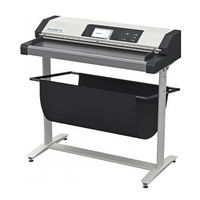
Image Access WideTEK 36 Setup Instructions (46 pages)
Brand:
Image Access
| Category:
Scanner
| Size: 1 MB
Table of Contents
Table of Contents
2
Revision History
4
Information about the Instructions and the Manufacturer
5
Keep Instructions with the Scanner
5
Design Features in Text
6
Design Features in Pictures
7
Associated Documents
7
Copyright
8
Contact Data of the Manufacturer in Germany
8
Technical Support
8
Contact Data of the Manufacturer in the U.S
8
Safety
9
Intended Use
9
Basic Safety Information
9
Avoiding Property Damage and Malfunctions
10
Responsibility of the Owner
11
Staff Qualifications
11
Design Features of Warning Notices
12
Formatting of Information Regarding Property Damage
12
Description
13
Purpose and Function
13
Widetek® 36/44/48 Overview
14
Rear View
16
Setup Menu Overview Screen
17
Rating Plate
18
Serial Number
20
User Interfaces
20
Device Location
21
Environment
21
Prepare for Setup
22
Connect the Power Supply
22
Establish the Network Connection
23
Positioning the Scanner on the Optional Floor Stand
23
Connect the Foot Switch
23
Connect the Optional Monitor
24
Connect the Optional Touchscreen
25
Switch on the Scanner
26
Switch off the Scanner
28
Perform Setup
30
Setup Wizard
30
Performing the Adjustments
32
Activate the Setup Menu
32
System Restore
35
Solid State Disk Software Failure
35
Restore Points
35
System Restore to Factory Settings
36
System Restore to User Settings
37
Cleaning
38
Technical Specifications
39
Optical System Widetek® 36
39
Optical System Widetek® 44
40
Optical System Widetek® 48
41
Document Specification
41
Electrical Specifications
42
Dimensions and Weight Widetek® 36
43
Dimensions and Weight Widetek® 44/48
44
Ambient Conditions
44
Image Access WideTEK 36 Setup Instructions (44 pages)
Brand:
Image Access
| Category:
Scanner
| Size: 1 MB
Table of Contents
Table of Contents
2
Revision Overview
4
Notes on the Instructions and the Manufacturer
4
Keep Instructions Available
4
Design Features in the Text
5
Design Features in Illustrations
6
Associated Documents
6
Copyright
7
Contact Details of the Manufacturer in Germany
7
Technical Support
7
Contact Details of the Manufacturer in the USA
7
Device Safety
8
Intended Use
8
Basic Safety Instructions
9
Avoid Material Damage or Malfunctions
10
Responsibility of the Operator
10
Personnel Qualification
10
Design Features of Warnings
11
Design Features of Notices of Damage to Property
11
Description
12
Task and Function
12
Overview Widetek® 36/44/48
13
Overview Back Side
15
Overview Screen Page for the Setup Menu
16
Rating Plate
17
Serial Number
19
User Interfaces
19
Installation Site
20
Environmental Conditions
20
Prepare Setup
21
Connecting the Power Supply
21
Establish Network Connection
22
Place the Scanner on the Optional Base
22
Connecting the Foot Switch
23
Connecting the Optional Monitor
23
Connect Optional Touch Screen
24
Switch on Scanner
25
Switch off Scanner
27
Perform Setup
29
Setup Wizard
29
Perform Calibrations
31
Activate Setup Menu
31
System Restore
34
Solid State Disk Software Error
34
Recovery Points
34
System Restore to Factory Defaults
35
System Recovery of User Settings
36
Cleaning
37
Technical Data
38
Optical System Widetek® 36
38
Optical System Widetek® 44
39
Optical System Widetek® 48
40
Document Specification
40
Electrical Specification
41
Dimensions and Weight Widetek® 36
42
Dimensions and Weight Widetek® 44/48
43
Environmental Conditions
43
Advertisement
Related Products
Image Access WideTEK 36 DS
Image Access WideTek 36C
Image Access bookeye 3
Image Access WideTEK 36CL
Image Access WideTEK 36ART
Image Access WideTEK 36CL-600
Image Access WideTEK 36ART-600
Image Access WideTEK 25
Image Access WideTEK 25-600
Image Access WideTEK A2
Image Access Categories
Scanner
Printer
Monitor
Racks & Stands
Scanners
More Image Access Manuals
Login
Sign In
OR
Sign in with Facebook
Sign in with Google
Upload manual
Upload from disk
Upload from URL