Table of Contents
Advertisement
Quick Links
Introduction
This user manual provides a hardware description of both versions of the STR9 Dongle:
STEVAL-IFD001V1 (full version)
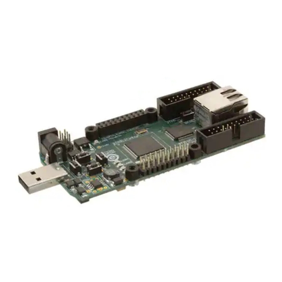
STEVAL-IFD001V2 (lite version)
Figure 1.
This document contains all the necessary assembly information to designers interested in
using STR9 Dongle including the block diagram, board schematics, footprints and PCB
layouts as well as the bill of materials and any additional assembly instructions.
June 2007
STR9 DONGLE (STEVAL-IFD001V2)
STR9 Dongle hardware description
Rev 3
UM0282
User manual
www.st.com
1/19
Advertisement
Table of Contents

Related Manuals for STMicroelectronics STR9 Series


Summary of Contents for STMicroelectronics STR9 Series
- Page 1 UM0282 User manual STR9 Dongle hardware description Introduction This user manual provides a hardware description of both versions of the STR9 Dongle: STEVAL-IFD001V1 (full version) STEVAL-IFD001V2 (lite version) Figure 1. STR9 DONGLE (STEVAL-IFD001V2) This document contains all the necessary assembly information to designers interested in using STR9 Dongle including the block diagram, board schematics, footprints and PCB layouts as well as the bill of materials and any additional assembly instructions.
-
Page 2: Table Of Contents
Contents UM0282 Contents STR9 Dongle ..........3 Block diagram . -
Page 3: Str9 Dongle
UM0282 STR9 Dongle STR9 Dongle Block diagram This board is based on an microcontroller STR912FAW34, STR912FAW42 or STR912FAW44 which provides calculation power up to 90MIPS. STR912FAW34, STR912FAW42 and STR912FAW44 are referred to STR912FAWxx throughout the document. Figure 2. STR9 Dongle block diagram 3.3V ANALOG_CONNECTOR Power... -
Page 4: Schematics
STR9 Dongle UM0282 Schematics Figure 3. Schematics 1 of 4 4/19... - Page 5 UM0282 STR9 Dongle Figure 4. Schematics 2 of 4 5/19...
- Page 6 STR9 Dongle UM0282 Figure 5. Schematics 3 of 4 Note: Refer to Section 1.2.1 on page 8 for pin connections of CN3, CN4 and CN5 connectors. 6/19...
- Page 7 UM0282 STR9 Dongle Figure 6. Schematics 4 of 4 7/19...
-
Page 8: Pin Connections
STR9 Dongle UM0282 1.2.1 Pin connections The following tables show the pin connections for the three connectors ANALOG_CON (CN5), DIGITAL_CON (CN4) and EXTENDED_CON (CN3). These are shown in Figure 5 on page Table 1. Analog connector, ANALOG_CON (CN5) GPIO UART In/Out ADC0 In/Out... -
Page 9: Suppliers
UM0282 STR9 Dongle Table 3. Extended connector, EXTENDED_CON (CN3) GPIO UART In/Out In/Out In/Out In/Out In/Out UART0_RX In/Out UART2_TX In/Out UART2_RX In/Out UART0_TX In/Out EXINT2 UART1_RX In/Out EXINT3 UART1_TX In/Out In/Out EXINT4 SSP0_SCLK - In/Out In/Out EXINT5 SSP0_MISO - In/Out EXINT6 SSP0_MOSI - In/Out... -
Page 10: Used Footprints
STR9 Dongle UM0282 Used footprints www.koala.cz: MC-146 www.koala.cz: CM5032 www.coilcraft.com: 0603PS-332KLC 10/19... -
Page 11: Pcb Layout
UM0282 STR9 Dongle PCB layout Figure 7. Top view 11/19... - Page 12 STR9 Dongle UM0282 Figure 8. Bottom view 12/19...
-
Page 13: Bill Of Materials
UM0282 STR9 Dongle Bill of materials Table 4. Chips Part Package Detail description Order code ST: STR912FAW34x6, STR912FAW34, STR912FAW42, LQFP128 STR912FAW42x6, STR912FAW44 STR912FAW44x6 TQFP64 Ethernet physical layer ST: STE100 or STE101 SOT23-6L DALC208 diode protection ST: DALC208SC6 Farnell: 501-1954 CAN transceiver (3V) (SN65HVD230-232) Table 5. - Page 14 STR9 Dongle UM0282 Table 7. Resistors Part Package Detail description Order code R709, R20 0603 GM: R0603-0R R62-R63 0603 GM: R0603-36R R707, R708 0603 GM: R0603-51R R710 0603 GM: R0603-100R 0603 GM: R0603-120R R714, R716 0603 GM: R0603-240R 0603 GM: R0603-240R R82, R83, 0603 GM: R0603-300R...
- Page 15 UM0282 STR9 Dongle Table 9. Power Part Package Detail description Order code (reference) = 3.3 V, ST: E-L5973D PW01 SO8cool typ. 200 mA, max. 500 = 35 V, Imax = 2.5 A, Rth = 40 C/W INmax Use external supply 5-24V) = 1.8 V, ST: LF18xDT PW02...
-
Page 16: Assembling Instructions
STR9 Dongle UM0282 Assembling instructions Table 14. JTAG with IAR Part Assembled Configuration / Comment Position 1-2 R24, R25 Position 2-3 R27, R28 Table 15. Configuration with STE101P Part Assembled Configuration / Comment R710 R707. R708 R709 R721-R725 Position 1-2 R726-R729 Position 2-3 1.7.1... -
Page 17: Assembling Instructions For Lite Version
UM0282 STR9 Dongle Assembling instructions for lite version CAN transceiver U9 – not assembled Connectors CN3, CN4, CN5, CN9 – not assembled Crystal X2 – use this one GM: 131-082 (Q32.768KHZM) Application hints 1.9.1 Ethernet interface Clock input The clock is provided directly by the STR912FAWxx device. It is mandatory to enable this feature on pin P52 before starting. -
Page 18: Revision History
Revision history UM0282 Revision history Table 16. Document revision history Date Revision Changes 19-Jan-2007 Initial release. 24-May-2007 Section 1.9: Application hints added. Figure 1: STR9 DONGLE (STEVAL-IFD001V2) updated. Root part numbers changed from STR912FW42xx and 19-June-2007 STR912FW44x to STR912FAW34, STR912FAW42 and STR912FAW44 throughout the document. - Page 19 Please Read Carefully: Information in this document is provided solely in connection with ST products. STMicroelectronics NV and its subsidiaries (“ST”) reserve the right to make changes, corrections, modifications or improvements, to this document, and the products and services described herein at any time, without notice.
Need help?
Do you have a question about the STR9 Series and is the answer not in the manual?
Questions and answers