Table of Contents
Advertisement
Quick Links
Advertisement
Table of Contents

Related Manuals for OCULUS Myopia Master Advanced


Summary of Contents for OCULUS Myopia Master Advanced
- Page 1 ® ® OCULUS Myopia Master INSTRUCTION MANUAL...
- Page 2 Our service team will gladly assist. OCULUS Optikgeräte GmbH OCULUS is certified according to DIN EN ISO 13485, setting high standards of quality for the development, manufacture, quality assurance and service of the entire range of products.
-
Page 3: Table Of Contents
Table of Contents Table of Contents Scope of Delivery.........................1 Graphic Symbols..........................2 Structure of the Documentation ....................3 Safety Instructions........................4 About this Manual ......................4 4.1.1 Pictograms Used in this Manual ..............4 Safety Instructions for Use ..................5 Intended Use..........................11 Transport to Installation Location..................12 Device Description ........................ - Page 4 Table of Contents 12.4 AR + K measurement and results................37 12.5 P + AR + K measurement and results..............39 12.6 PARK + AXL and results .....................41 12.7 Axial length and results .....................43 12.8 Printing and Saving Examinations................44 12.8.1 Printing......................45 12.8.2 Saving an examination................45 12.9 Complete measurement .....................46 13 Chronology of Different Measuring Processes..............47...
- Page 5 Table of Contents 22 Terms of Warranty and Servicing ..................76 22.1 Terms of Warranty ...................... 76 22.2 Assumption of Liability for Functions and Damage .......... 76 22.3 Manufacturer and Service Address ................ 77 23 Technical Data .......................... 78 24 Annex............................82 24.1 Electromagnetic Compatibility................
- Page 6 Table of Contents v / v Instruction Manual Myopia Master® (G/68100/EN Rev04 0820)
-
Page 7: Scope Of Delivery
1 Scope of Delivery Scope of Delivery Products and accessories Order number Version 68100 Myopia Master® Advanced, with chin and head rest, with Scheimpflug camera (fully equipped) 68110 Myopia Master® Advanced, without chin and head rest, with Scheimpflug camera 68120 ... -
Page 8: Graphic Symbols
2 Graphic Symbols Note We reserve the right to change the scope of delivery in line with ongoing technical development. Software versions The instruction manuals describe the following Software Set version: 1.1r2 Graphic Symbols Symbols equipment Symbols packaging Manufacturer Protection class Keep dry Date of IP XX... -
Page 9: Structure Of The Documentation
3 Structure of the Documentation Additional Symbols and abbreviations on power adapter Indoor use only Testing center Aquivalent to RoHS Conform to US and Nemkos symbol Chinese Standard Canadian standards Sign Meets German Polarity of safety requirements DC connector Fig. 2-1: Name plate (example) There are no temporarily fixed markings on the device. -
Page 10: Safety Instructions
4 Safety Instructions Safety Instructions About this Manual Carefully read through the Instruction Manual. Keep the Instruction Manual in good condition near the device. Observe the legal regulations with regard to accident prevention. 4.1.1 Pictograms Used in this Manual Warning Identifies a potentially dangerous situation which may cause irreversible injury. -
Page 11: Safety Instructions For Use
who can guarantee proper handling due to their knowledge, training and practical experience. who have been instructed by OCULUS staff or an authorized dealer before the initial operation. Transport and Storage Instructions Refer to the notes in sec. 20, page Instructions for Setup and Connection ... - Page 12 If you find damage to the plug connector, have the damage corrected by our service department. Establish an USB connection only with the OCULUS USB FS MED- Isolator (Nr. 01 56920 00 010). Note that an output voltage of maximum 5.5 V DC is supplied by a device connected via USB.
- Page 13 Before first use: Let OCULUS or an authorized dealer train you in the operation of the Myopia Master®. Only operate the device if you have understood the operating instructions.
- Page 14 4 Safety Instructions Do not put any heavy objects onto the unit or the cables. Do not put the Myopia Master® down onto devices that produce heat, heaters (e.g. radiators), microwaves or similar. Make sure that the device cannot tip over by leaning against it or sitting on it.
- Page 15 Only use the power adapter listed in the packing list. Establish an USB connection only with the OCULUS USB FS MED- Isolator (Nr. 01 56920 00 010). Use only a computer that meets the specifications given in this instruction manual, sec.
- Page 16 4 Safety Instructions Cybersecurity Do not use the Myopia Master® with wireless technology, for example with wireless USB To ensure cyber security in order to the usage of the device, the following security measures should be considered. Contact your computer administrator: Precautions for access control of the computer ...
-
Page 17: Intended Use
5 Intended Use Intended Use The Myopia Master® is designed to photograph the eye and take Scheimpflug images of the anterior segment to evaluate the thickness of the cornea. The integrated keratometer measures the central radii of the cornea. The integrated ophthalmic refractometer measures the refractive power of the eye. -
Page 18: Transport To Installation Location
6 Transport to Installation Location Transport to Installation Location The transport and storage conditions see sec. 20, page Wait approx. 3-4 hours after transport before operating the Myopia Master®. Extreme temperature changes from cold areas to warm rooms can cause condensation on the optical components. Note Equipment damage due to incorrect transport and improper storage ... -
Page 19: Device Description
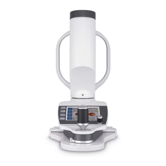
7 Device Description Device Description Overview of Device Components Gauge head Control Wheel Function keys Printout slot Sliding plate Display Joystick Fig. 7-1: Device components Instruction Manual Myopia Master® (G/68100/EN Rev04 0820) 13 / 92... - Page 20 7 Device Description Head rest On/Off Switch USB port Marking for the eye height Control LED Chin rest Pachycam camera glass cover Mains connection Measuring ocular / Patient eyepiece with Keratometer ring Fig. 7-2: Device components 14 / 92 Instruction Manual Myopia Master® (G/68100/EN Rev04 0820)
-
Page 21: Mode Of Operation Of The Myopia Master
7 Device Description Mode of Operation of the Myopia Master® The Myopia Master® combines different measuring functions in one unit. Auto-Refractometer An infrared light source projects measuring light onto the retina of the eye from where it is reflected back to the shutter location. Sensitive sensor chips, or CCD cameras now register the deviation of the reflected light from the shutter location. - Page 22 7 Device Description Applied parts 1 Head rest 2 Chin rest Fig. 7-3: Applied parts 16 / 92 Instruction Manual Myopia Master® (G/68100/EN Rev04 0820)
-
Page 23: Set Up And Connection
Before first use, make sure the installation and connection of the "Myopia Master®" examination station are completed by our service team or by a professional authorized by OCULUS. Note Do not expose the Myopia Master® to any vibrations, shocks, contaminants, moisture, or high temperatures. - Page 24 8 Set up and Connection If you use a multiple socket outlet to connect the Myopia Master®: Use a multiple socket outlet that complies with the requirements of IEC 60601-1. Do not place the multiple socket outlet on the floor. ...
-
Page 25: Integrate Into It Network For Service Purposes
If your computer is already integrated into an IT network, the following information will apply. Caution Risk of incorrect measurements/equipment damage due to unauthorized personal Ensure that only an expert, authorized by OCULUS connects the computer. updates the firmware. Risk of incorrect measurements/equipment damage due to incorrect connection Each connection of a Myopia Master®... -
Page 26: Operation
9 Operation Operation Wait approx. 3-4 hours after transport before operating the Myopia Master® for the first time. Extreme temperature changes from cold areas to warm rooms can cause condensation on the optical components. Switching On Turn on the Myopia Master® with the On/Off Switch (position I). The LED lights up green. -
Page 27: Functions Of The Control Pad
10 Functions of the Control Pad 10 Functions of the Control Pad Joystick button Joystick with turning handle Display Compound slide Control wheel Functions assigned to buttons Fig. 10-1: Functions on the control pad Component Function Operation Functions assigned Activates the adjacent keypad, de- Press the desired button. -
Page 28: Touch Screen
10 Functions of the Control Pad 10.1 Touch Screen If the function is not activated: Enable the checkbox in "Setting 2/5"(sec. 15.2, page 54), In addition to the function keys, you can now also use the buttons on the screen, for example you can enable the respective button by gently pressing it on the touch screen. -
Page 29: Preparing Patients Data
11 Preparing Patients Data 11 Preparing Patients Data Use the patient data management if you want to assign the examinations to a patient or want to save them long-term. In that case, enter the patient’s name and date of birth before you conduct the measurement. -
Page 30: Entering New Patients (Touch Screen Deactivated)
11 Preparing Patients Data The name of the patient appears in the list. Fig. 11-2: Patient list Press the [Measure] button to switch to measuring mode. 11.2 Entering new Patients (touch screen deactivated) To input a new patient, press the button [Patient] in the patient data menu. -
Page 31: Selecting Existing Patients
11 Preparing Patients Data To correct an incorrect entry: Press the [Delete Char] button to delete one character. Press the [Delete Line] button to delete the whole entry in the field. Alternatively, you can delete the entered text with the control wheel ". -
Page 32: Rename A Patient
11 Preparing Patients Data 11.2.2 Rename a Patient Select the patient that you want to rename. Press the button. Enter the new name in the field "New Name", or enter a new date of birth. Confirm your input. 11.2.3 Delete a Patient or an Examination If you want to delete a patient or an examination:... -
Page 33: Load An Examination
11 Preparing Patients Data 11.2.4 Load an Examination Fig. 11-5: Load an Examination All examinations can be reloaded and print out at a later date. If two examinations have already been printed out together, these are also automatically saved together (R+L) and in turn, they are also reloaded together. -
Page 34: Measuring Procedure
12 Measuring Procedure Caution Risk of incorrect measurement due to incorrect use Before first use: Let OCULUS or an authorized dealer train you in the operation of the Myopia Master®. A measuring procedure consists of the following steps: ... -
Page 35: Preparing A Measurement
12 Measuring Procedure Press the [Mode] button to change the combination of measuring functions for the individual measurement. The other parameters that have been selected in "Settings" remain active (sec. 15, page 52). The eye that is being measured is shown at the bottom right, [R] for right or [L] for left. - Page 36 12 Measuring Procedure Note When "Eye-tracking" is active, height adjustment takes place automati- cally. What to say to the patient: "Look into the eyepiece. You will see a balloon. Relax and look at its center". Adjust the compound slide until the image of the patient’s eye is sharply focussed on the display.
- Page 37 12 Measuring Procedure Note In the measuring procedure described here, the relative measuring func- tions „Myopia“ are activated. First the central corneal radii are measured, then the refraction is per- formed followed by the axial length measurement. Furthermore, "Eye-tracking" and "Auto-release" are standardly activated. At the bottom of the screen, you can see whether measurements have already been taken and saved for the respective eye.
-
Page 38: Myopia Measurement And Results
12 Measuring Procedure 12.3 Myopia measurement and results The measurement mode is preset to "Myopia". Fig. 12-4: Measuring mode These steps belong to a complete myopia measurement central cornea radii (K) objective refraction (ARK) axial length (AXL) 12.3.1 Myopia Overview Display The measured values of the myopia examination are displayed in the... -
Page 39: Myopia Results
12 Measuring Procedure Press the button to change to the prognosis display. 12.3.2 Myopia Results After performing the measurement the following display appears. 1 Patient and examination data 4 Risk assesment 2 Colour for examined eye 5 Measurement values of the patients 3 Type of notation 6 Progressive representation of axial lengths and objective refraction... - Page 40 12 Measuring Procedure The following display appears. 1 Patient and examination data 2 Further risk factors Fig. 12-7: Risk factors display The questionnaire gives you a brief risk assessment. The risk is classified according to scientific studies. Ask the patient about his/her: ethnicity ...
-
Page 41: Refraction Results
12 Measuring Procedure 12.3.3 Refraction Results After performing the measurement the following display appears.. 1 Patient and examination data 3 Keratometer 2 Refraction values 4 Scheimpflug images Fig. 12-8: AR + K overview display Refraction Values (2) The sphere, cylinder, axis position and quality values are displayed in this field. -
Page 42: Axial Length Results
12 Measuring Procedure critical; repeat the measurement, if necessary. If the field has a red background ( 6) - repeat the measurement. Camera image (4) The cornea or the edge of the iris is marked in the camera image. 12.3.4 Axial length results After performing the measurement the following display appears. -
Page 43: Ar + K Measurement And Results
12 Measuring Procedure 12.4 AR + K measurement and results The AR + K values can be measured independently. Select the mode AR + K. Fig. 12-10: Measuring mode AR + K The measurement AR + K is executed for both eyes. The following screen appears. - Page 44 12 Measuring Procedure Refraction Values (2) The sphere, cylinder, axis position an quality values are displayed in this field. The refraction values are measured three times. The mean value is displayed in the fourth line. Q-value: If the field has a white background (9-8) - the measuring results are good. If the field has a yellow background (7-6) - the measuring results are critical;...
-
Page 45: P + Ar + K Measurement And Results
12 Measuring Procedure 12.5 P + AR + K measurement and results If your device is equipped with a pachymeter the corneal thickness can be measured additionally. Select the mode P + AR + K. Fig. 12-12: Measuring mode P + AR + K If the measurement mode was executed, the following overview screen appears for the examination of the right eye. - Page 46 12 Measuring Procedure Pachymeter values (3) P. Apex: Corneal thickness at the apex P. Min: Corneal thickness at the thinnest point Q-value: If the field has a white background (9-8) - the measuring results are good. If the field has a yellow background (7-6) - the measuring results are critical;...
-
Page 47: Park + Axl And Results
12 Measuring Procedure 12.6 PARK + AXL and results If your device is equipped with a pachymeter the corneal thickness can be measured additionally. Select the PARK + AXL mode. Fig. 12-14: Measuring mode PARK + AXL If the measurement mode were executed, the following overview screen appears for the examination of the right eye: 1 Patient and examination data 3 AXL images and values... - Page 48 12 Measuring Procedure Refraction Values (2) The sphere, cylinder, axis position and quality values are displayed in this field. SEQ: Spherical equivalent Q-value: If the field has a white background (9-8) - the measuring results are good. If the field has a yellow background (7-6) - the measuring results are critical;...
-
Page 49: Axial Length And Results
12 Measuring Procedure 12.7 Axial length and results To measure the axial length of the eye only select the AXL mode. Select the AXL mode. Fig. 12-16: Measuring mode AXL If the measurement mode were executed, the following overview screen appears for the examination of the right eye: 1 Patient and examination data 3 SNR values... -
Page 50: Printing And Saving Examinations
12 Measuring Procedure 12.8 Printing and Saving Examinations After performing the measurement of the myopia the following display appears.: Fig. 12-18: Display with print button 44 / 92 Instruction Manual Myopia Master® (G/68100/EN Rev04 0820) -
Page 51: Printing
12 Measuring Procedure 12.8.1 Printing Press the [Print] button to print out the examination results. Note The measurement is automatically saved if you entered a new patient (sec. 11.1, page 23) prior to starting the measuring process. When printed out, each measurement is automatically temporarily saved to the exam nr. -
Page 52: Complete Measurement
12 Measuring Procedure Saving data by Exam no. memory After printing, each examination is automatically saved in the exam no. memory and can be retrieved from there later. A maximum of 100 examinations can be stored in the exam nr. memory, after which the first measurement that was saved is overwritten again. -
Page 53: Chronology Of Different Measuring Processes
13 Chronology of Different Measuring Processes 13 Chronology of Different Measuring Processes The chronology of three different measuring processes is outlined briefly below. You enter a patient in the patient data management and then con- duct the measurement. The examination data are automatically saved under the newly entered patient’s name (sec. -
Page 54: Saving An Examination Retroactively
13 Chronology of Different Measuring Processes 13.2 Saving an Examination Retroactively Start the measuring operation directly. The following screen appears: Fig. 13-1: Start a new measurement Select "Start a new measurement anyway“. Conduct the measurement (sec. 12, page 28). -
Page 55: Measuring Without Saving The Patient Data
13 Chronology of Different Measuring Processes You can enter a new a patient and save the conducted measure- ment under that patient's name. You must first exit the patient list. The patient data management is already opened (fig. 11-1, page 23). -
Page 56: Reference Measurement
after changing the position of the Myopia Master® The first reference measurement is performed during setup by OCULUS or an authorized dealer. OCULUS recommends performing a reference measurement once each month. The reference measurement can be performed easily and quickly using the reference tool. - Page 57 14 Reference Measurement Fig. 14-2: Example: Result on reference tool The system is now ready for operation. Instruction Manual Myopia Master® (G/68100/EN Rev04 0820) 51 / 92...
-
Page 58: Settings
15 Settings 15 Settings Choose the default settings for your individual measuring mode. 15.1 Settings 1 Fig. 15-1: Settings 1 Measuring Mode You can preset the measuring function combinations here. Myopia Contr.: Myopia measurement AR + K: Refraction+Keratometry P + AR + K: Pachymetry+Refraction+Keratometry PARK + AXL: Pachymetry+Refraction+Keratometry+axial length AXL: axial length measurement You also activate or deactivate the functions "Eye-tracking"... - Page 59 15 Settings Cyl mode Select whether plus or minus cylinders are to be used. When the program is started, this preselected cylinder type is then always active. K-Value Style Select the mode for determining how the central radii are to be displayed. Rh Rv: horizontal / vertical radius K1 K2: Flat radius / Steep radius K-Value Unit...
-
Page 60: Settings 2
15 Settings 15.2 Settings 2 On the "Settings 1" screen, press the button [Next Page]. Fig. 15-2: Settings 2 Clock - Date Format In these two fields, you set the time and the date by turning and pressing the rotary knob. Display You can adjust the brightness of the display here. - Page 61 15 Settings Interface You can deactivate the interfaces. With the GDT interface, you can link the Myopia Master® to an existing office software and can thus import and export data. If you want to connect a phoropter that is supported by PARK (fig.
-
Page 62: Settings 3
15 Settings 15.3 Settings 3 On the "Settings 3" screen, you set the communication parameters for the respective phoropter: Fig. 15-4: Settings 3 Examples of communication parameters of phoropters that are supported by Myopia Master® (Status: December 2019): Manufacturer Phoropter Baud rate Parity Stop bits... -
Page 63: Settings 4
15 Settings 15.4 Settings 4 Fig. 15-6: Settings 4 On the "Settings 4" screen, you can individually configure the printout. Print AR Details Print AR Details: activated Print AR Details: activated Print Keratometer Details Print single line K-Values: activated Instruction Manual Myopia Master® (G/68100/EN Rev04 0820) 57 / 92... - Page 64 Enter the appropriate information in the lines provided for that purpose and activate the checkboxes in front of each line. OD/OS According to the settings R (right) and L (left) is printed out or OD (oculus dexter) and OS (oculus sinister). 58 / 92...
-
Page 65: Settings 5
15 Settings 15.5 Settings 5 Fig. 15-7: Settings 5 Instruction Manual Myopia Master® (G/68100/EN Rev04 0820) 59 / 92... -
Page 66: Display Options
16 Display Options 16 Display Options In addition to the overview of the measuring results for an eye (fig. 12-5, page 32), you can also select other display settings. To access the available, press the [Display] button repeatedly. Examination results for both eyes: Refraction and Keratometry Fig. - Page 67 16 Display Options Display of Pachymetry 1 Scheimpflug image 2 Corneal thickness range (Measuring range: horizontal 4mm section through the apex) Fig. 16-2: Overview Pachymetry Press in the "Corneal thickness progression" field on the touch screen. The device shows you the exact location of the cornea at the selected spot.
-
Page 68: Calculated Correction Of Tonometrically Measured Iop
17 Calculated correction of tonometrically measured IOP 17 Calculated correction of tonometrically measured IOP Independent studies have shown that tonometric measurements of intraocular pressure (IOP) are influenced by the thickness and curvature of the cornea in its center. This systematic measurement error can only be eliminated by calculation. -
Page 69: Post-Lasik Iop Correction
17 Calculated correction of tonometrically measured IOP The diagram below shows the progression of the correction summand over a range of corneal thickness as given by the three formula: Fig. 17-1: Progression-diagram Each formula gives a different way of calculating the IOP correction summand, as follows: Ehlers: IOP change = 0.071 * (545 µm - corneal thickness... -
Page 70: Iop Correction Based On Central Corneal Thickness And Corneal Curvature
17 Calculated correction of tonometrically measured IOP 17.3 IOP correction based on central corneal thickness and corneal curvature The formula developed by Orssengo and Pye considers not only the corneal thickness but also the corneal curvature in calculating the corrected IOP. This yields a factor with which the true IOP can be estimated from the measured IOP. -
Page 71: Performing Iop Correction With The Myopia Master
17 Calculated correction of tonometrically measured IOP 17.4 Performing IOP correction with the Myopia Master® Select an IOP-Table in the menu "Settings 1" (sec. 15.1, page 52). Perform a P+AR+K or a PARK + AXL measurement (sec. 12, page 28). -
Page 72: Save The Iop Data
17 Calculated correction of tonometrically measured IOP Note By default, the IOP correction is calculated by the correction formula, which was selected in the settings. If another formula should be used (for example myopic post-LASIK), you can select it on the screen of the IOP correction. ... -
Page 73: Cleaning, Disinfection And Maintenance
18 Cleaning, Disinfection and Maintenance 18 Cleaning, Disinfection and Maintenance This chapter describes how to clean, disinfect, and maintain the Myopia Master®. Sterilization is not required. Always pay attention to the product descriptions and instruction manuals of any materials or products that you use to care for, clean, and disinfect the device and/or its accessories. - Page 74 18 Cleaning, Disinfection and Maintenance 1 Head rest Chin rest 2 Protective glass covers Abb. 18-1: Cleaning Cleaning head rest and chin rests The Myopia Master®can be switched on for cleaning the head rest and chin rest. During the measuring process, sweat, cosmetics, etc. from the patient can get on the head and chin rest.
-
Page 75: Disinfection
18 Cleaning, Disinfection and Maintenance Protective glass covers for the optics The openings in the housing for the optics are covered by protective glass covers which must be kept dust- and dirt-free. If they are dirty, clean the lens protection glass with a lint-free cloth moistened with alcohol. -
Page 76: Maintenance
If a fault occurs that you cannot rectify: Label a damaged Myopia Master® as non-operational. Report the damage to OCULUS Service or to your authorised dealer. Only use an undamaged Myopia Master®. Additional measures are not required during preventive maintenance. -
Page 77: Attaching Paper To The Chin Rest
18 Cleaning, Disinfection and Maintenance Caution Risk of personal injury or material damage due to invisible laser radiation The Myopia Master® contains a Class 1 laser according to DIN EN 60825- 1:2015 and DIN EN 60825-1: 2001. It is an encapsulated laser system. When the Myopia Master®... - Page 78 18 Cleaning, Disinfection and Maintenance Flip up the display Fig. 18-3: Display for advancing and reversing the feed roller You can advance and reverse the printer paper by pressing the buttons "Printer Feed" and "Feed Back" accordingly. To change the printer paper: ...
-
Page 79: Troubleshooting
19 Troubleshooting 19 Troubleshooting Caution Risk of personal injury or equipment damage due to improper troubleshooting Do not plug in or pull out any cables while the Myopia Master® is switched on. If an error occurs which you are unable to correct by following the instructions below, label the device as "out-of-order"... -
Page 80: Dismantling, Transport And Storage
20 Dismantling, Transport and Storage 20 Dismantling, Transport and Storage The Myopia Master®, must be properly dismantled and packed before being transported or stored. 20.1 Disassembly End the current session. Switch off the Myopia Master® with the On/Off Switch. ... -
Page 81: Disposal
21 Disposal Do not hold the device by the joystick to carry it. Store the Myopia Master® in compliance with the storage conditions. Avoid placing near heaters and moisture. 21 Disposal In accordance with Directive 2012/19/EC of the European Parliament and the Council, and in accordance with German law governing the marketing, return and environmentally compatible disposal of used electrical and electronic devices, such appliances must be recycled and... -
Page 82: Terms Of Warranty And Servicing
This certification must contain the date of performance and statement of the performing firm, with signature. If requested, OCULUS will provide the service technician with a list of spare parts and additional descriptive material for this purpose. -
Page 83: Manufacturer And Service Address
22 Terms of Warranty and Servicing 22.3 Manufacturer and Service Address Supplemental information is available from our Service Department or from our authorized representatives. Manufacturer and Service address: OCULUS Optikgeräte GmbH Münchholzhäuser Straße 29 35582 Wetzlar GERMANY Tel. +49 641 2005-0 Fax +49 641 2005-295 E-Mail: export@oculus.de... -
Page 84: Technical Data
23 Technical Data 23 Technical Data Measuring modes Myopia, AR + K, P + AR + K, PARK + AXL, AXL Measuring range Distance-pD 20 up to 80 mm (in 1mm steps) Measuring range 10 up to 14 mm (in 0,1 steps) Cornea diameter Measuring range 1 up to 8 mm (in 0,1 steps) - Page 85 23 Technical Data Axial length Axial length 14 — 40 mm Classification according to IEC 60601 - 1 Protection against electric shock: Protection class Insulation of applied parts: Type Type B Protection against foreign objects, contact and IP20 water Ambient operating requirements Temperature +10 —...
- Page 86 23 Technical Data Power adapter Netzteil GSM60B15-P1J (05150725) AC input 80 — 264 VAC Frequency 47 — 63 Hz DC output 15 V DC/4 A, 60 W max. Fuses Integrated overcurrent shut-off General Dimensions height x width x depth 266 x 538 x 493 – 523 mm Weight 12 kg Voltage...
- Page 87 23 Technical Data Classification according to DIN EN 60825-1:2015 and DIN EN 60825-1: 2001 The unit contains a Class 1 laser. Maximum output of the laser radiation 0.7 mW Single pulse duration 510 – 760 ms Pulse count per examination Wavelength 880 nm Instruction Manual Myopia Master®...
-
Page 88: Annex
EMC, and must be installed and operated according to the EMC-Instructions contained in the accompanying paperwork. No special measures need be observed in respect of OCULUS devices and systems. Portable and mobile RF-communications devices can interfere with electrically operated medical devices. - Page 89 24 Annex To be in compliance with the requirements of the IEC 60601-1-2 the following types of equipment, accessories, power adapters and cables must be used. Order number Description Myopia Master® Advanced, 68100 with chin and head rest, with Scheimpflug camera (fully equipped) Myopia Master®...
-
Page 90: Guidance And Manufacturer's Declaration - Electromagnetic Emmisssions And Immunity For The Myopia Master
Guidance and manufacturer´s declaration electromagentic emmissions IEC 60601-1-2: 2015, based to table 1 The OCULUS Myopia Master® is intended for operation in the electromagnetic environment specified below. The user of the Myopia Master® should ensure that it is being used in such an environment. - Page 91 24 Annex Electromagentic immunity, IEC 60601-1-2: 2015, based on table 4 Immunity test IEC 60601 Compliance level Electromagnetic environment - test level guidance Electrostatic discharge ± 8 kV contact ± 8 kV Floors should be made of wood (ESD) ± 15 kV or concrete or covered with ±...
- Page 92 24 Annex Electromagentic immunity, IEC 60601-1-2: 2015, based on table 4, 5 Immunity test IEC 60601 Compliance level Electromagnetic environment - Guidelines test level Portable and mobile RF communications equip- ment should be used no closer to any part of Myopia Master®, including cables, than the re- commended separation distance calculated from the equation applicable to the frequency of...
- Page 93 24 Annex Recommended separation distances between portable and mobile RF communications equipment and the Myopia Master®, IEC 60601-1-2:2007, table 6 The Myopia Master® in intended for use in an electromagnetic environment in which radiated RF disturbances are controlled. The customer or the user of the Myopia Master® can help prevent electromagnetic interference by maintaining a minimum distance between portable and mobile RF communications equipment (transmitters) and the Myopia Master®...
-
Page 94: Description Of The Connection
24 Annex 24.3 Description of the Connection ® Myopia Master Power supply adapter Y cable (05150725) 05200600 USB isolator Computer/PC/Laptop Mains connection 88 / 92 Instruction Manual Myopia Master® (G/68100/EN Rev04 0820) -
Page 95: Data Sheet Gsm60B15-P1J (05150725)
24 Annex 24.4 Data Sheet GSM60B15-P1J (05150725) Instruction Manual Myopia Master® (G/68100/EN Rev04 0820) 89 / 92... - Page 96 24 Annex 90 / 92 Instruction Manual Myopia Master® (G/68100/EN Rev04 0820)
- Page 97 24 Annex Instruction Manual Myopia Master® (G/68100/EN Rev04 0820) 91 / 92...
- Page 98 Manufacturer and Service Address Headquarters: OCULUS Optikgeräte GmbH Münchholzhäuser Straße 29 • 35582 Wetzlar • GERMANY Tel. +49 641 2005-0 • Fax +49 641 2005-295 E-Mail: export@oculus.de • www.oculus.de USA: OCULUS, Inc. 17721 59th Avenue NE • Arlington • WA 98223 Tel.
Need help?
Do you have a question about the Myopia Master Advanced and is the answer not in the manual?
Questions and answers