Table of Contents
Advertisement
Quick Links
INSTRUCTION MANUAL
INSTALLATION | WIRING | COMMISSIONING | MAINTENANCE |
I S O 9 0 0 1
ISO 14001
Q u a l i t é
Environnement
AFNOR CERTIFICATION
AFNOR CERTIFICATION
JBRB ECOWATT
PR
®
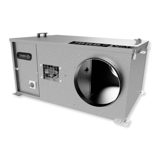
Collective residential building controlled mechanical ventilation
Tertiary premise ventilation 400°C 1/2hr C4 approved
Efectis certificate: EFR-16-002341
NT00000603-JBRB-ECOWATT-PR-AN-191202
Advertisement
Table of Contents

Related Manuals for ViM JBRB ECOWATT PR


Summary of Contents for ViM JBRB ECOWATT PR
- Page 1 INSTRUCTION MANUAL INSTALLATION | WIRING | COMMISSIONING | MAINTENANCE | I S O 9 0 0 1 ISO 14001 Q u a l i t é Environnement AFNOR CERTIFICATION AFNOR CERTIFICATION JBRB ECOWATT ® Collective residential building controlled mechanical ventilation Tertiary premise ventilation 400°C 1/2hr C4 approved Efectis certificate: EFR-16-002341 NT00000603-JBRB-ECOWATT-PR-AN-191202...
-
Page 2: Table Of Contents
CONTENTS GENERAL INFORMATION ........................ 3 Warnings ..........................3 Safety instructions ........................3 Reception - Storage........................3 Warranty ..........................4 PRODUCT PRESENTATION ......................4 Description..........................4 Aeraulic curves ........................7 INSTALLATION ..........................9 Dimensions and weight ......................9 Handling ..........................13 Choice of location ........................ -
Page 3: General Information
GENERAL INFORMATION 1.1 Warnings This product has been manufactured according to rigorous technical rules of safety in conformity with EC standards. The EC declaration may be downloaded from the Internet site (address given on the last page). Before installing and using this product, carefully read these instructions, which contain important indi- cations for your safety and the user’s safety during the installation, commissioning and maintenance of this product. -
Page 4: Product Presentation
1.4 Warranty The equipment is covered by a 12-month parts-only warranty from the billing date. The seller undertakes to replace all parts or equipment that it recognises as malfunctioning, to the exclu- sion of any damages or penalties such as operating losses, market injury and other non-material or indirect damage. - Page 5 Operating modes COP mode: Constant pressure control This operating mode is used to maintain constant pressure in the network over the fan’s entire used oper- ating range. Network pressure drops (register opening/closing, dual-flow vents, etc.) modify the pressure in the ventilation unit inlet plenum. This pressure is measured by a sensor built into the RMEC controller.
- Page 6 VAV mode: Variable airflow control according to analogue input In VAV mode, the airflow varies linearly, according to a setting signal (voltage 0-10V or current 4-20mA), between a min. airflow and a max. airflow to be set in the RMEC controller. Each signal value corresponds to an airflow maintained constant irrespective of network pressure drops.
-
Page 7: Aeraulic Curves
2.2 Aeraulic curves JBRB ECOWATT PR 04 COP JBRB ECOWATT PR 06 COP ® ® P (Pa) P (Pa) stat stat 100% 100% Qv (m Qv (m P (W) P (W) 100% 100% Qv (m Qv (m JBRB ECOWATT PR 10 COP JBRB ECOWATT PR 22 COP ®... - Page 8 JBRB ECOWATT PR 30 COP JBRB ECOWATT PR 38 COP ® ® P (Pa) P (Pa) stat stat 100% 100% Qv (m Qv (m 1000 1500 2000 2500 3000 3500 4000 4500 1000 1500 2000 2500 3000 3500 P (W) P (W) 100% 100%...
-
Page 9: Installation
JBRB ECOWATT PR 82 COP JBRB ECOWATT PR 92 COP ® ® P (Pa) P (Pa) P (W) stat stat 2400 100% 100% 2100 1800 1500 1200 Qv (m Qv (m 2000 4000 6000 8000 10000 1000 2000 3000 4000 5000 6000 7000... - Page 10 JBRB ECOWATT PR 48 / 70 / 82 / 92 ® Horizontal discharge - L / M configuration Sense of the air Sense of the air Sense of the air Only available on modular version Model Weight (kg) JBRB ECOWATT PR 48 1165 1,065 ®...
- Page 11 JBRB ECOWATT PR 48 / 82 / 92 ® Horizontal discharge - D configuration Sense of the air Sense of the air Only available on modular version Sense of the air Model Weight (kg) JBRB ECOWATT PR 48 1,490 1,105 ®...
- Page 12 JBRB ECOWATT PR 48 / 70 / 82 / 92 ® Vertical discharge - L / M configuration Sense of the air Sense of the air Only available on modular version Model Weight (kg) JBRB ECOWATT PR 48 1,119 1,065 ®...
-
Page 13: Handling
JBRB ECOWATT PR 48 / 82 / 92 ® Vertical discharge - D configuration Sense of the air Sense of the air Sense of the air Model Weight (kg) JBRB ECOWATT PR 48 1,444 1,105 ® JBRB ECOWATT PR 82 1,767 1,237 1,016 1,032 ®... -
Page 14: Choice Of Location
3.3 Choice of location JBRB ECOWATT PR 04 to 38 JBRB ECOWATT PR 48 to 92 ® ® Leave the height of the unit above the unit and on the door side for device commissioning and mainte- nance. 3.4 Ceiling-mounted installation JBRB ECOWATT PR 04 to 38 Ceiling-mounted installation ®... -
Page 15: Aeraulic Connection
3.5 Accessories assembly Circular connection to discharge Fasten the sealed flat bracket using 6 self-drilling screws (not supplied). Modulable coudé à 90° / For a unit not connected to discharge, add a vent cowl (CP) to enable 360° exhaust air outlet around double aspiration à... -
Page 16: Electrical Connection
ELECTRICAL CONNECTION 5.1 Prior precautions Models 30 to 92: This electronic-switching motor cannot be powered directly by mains power, on pain of destruction. Its power must be supplied by the controller. The device must be turned on and off via the RMEC local con- trol (wiring, see §"6.6 Local On/Off control (factory setting)", page 27) or via the BCCA external On/Off control (wiring, see "5.4 Electrical connection of an external On / Off control", page 17). -
Page 17: Electrical Connection Of An External On / Off Control
JBRB ECOWATT PR 30 to 82 Single-phase ® JBRB ECOWATT PR 30 to 92 Three-phase ® L1 L2 L3 To access the on-off switch terminals, unscrew the door’s 2 M8 screws using a 13mm spanner. Add a cable gland to the power cable and connect it to the on-off switch terminals. 5.4 Electrical connection of an external On / Off control The RMEC controller has a local On-Off control: an external On-Off control can be connected to terminals DI1 and GND. -
Page 18: Relay Electrical Connection - Ventilation Fault
5.5 Relay electrical connection - ventilation fault 5.5.1 Relay electrical connection - Model 04 to 22 Alim 230V 400V power supply PRESSURE SENSORS – – Ventilation fault wiring Open contact - Stop of the fan 5.5.2 Relay electrical connection - Model 30 to 82 single-phase Compacto Relay fault 9 10 11 12 13 14 15 16 17... -
Page 19: Electrical Connection Of Optional Tcom Remote Control
5.5.3 Relay electrical connection - Model 30 to 92 three-phase Invento Relay fault 10 11 12 13 14 15 16 17 18 19 Ventilation fault wiring Open contact - Stop of the fan Unit status Relay status “Normal” operation Power supply shut off On/Off contact - The wheel is stationary but the conductor is powered up Phase loss - In case of phase loss, the wheel may continue to turn NC check-list... - Page 20 Permanent connection: • Required when permanently installed on the system. • An extra HE13 quick connector is supplied with the remote control (self-crimping Comatel 478 se- ries). • It must be connected with a 0.2mm²-section (AWG 22 or 24 gauge), 3-conductor cable, maximum length: 100 metres.
-
Page 21: Electrical Connection Of A 2V Bcca
230V 5.7 Electrical connection of a 2V BCCA power supply PRESSURE SENSORS – – 0 LS HS BCCA 2V Illustration of the 2V BCCA contacts in low-air volume “on” position (minAV), LS position. To set the 2 airflow settings, please refer to § "6.10 CAV: Constant airflow – 2 settings", page 29 21/48 NT00000603-JBRB-ECOWATT-PR-AN-191202... -
Page 22: Electrical Connection Of A Sensor (Optional Accessory)
5.8 Electrical connection of a sensor (optional accessory) The unit can operate in VAV mode (air volume control, setting by analogue input). Please refer to the paragraphs “VAV: Sensor-type analogue input air volume control”. For VAV mode, a (SCO2, STEM, SHUR)-type sensor can be connected. SCO2 A/AA: 230V power... -
Page 23: Electrical Connection Of A Potentiometer (Optional Accessory)
For SHUR and STEM sensors, please refer to their respective manuals. Sonde When the sensor transmits a current signal, the switch must be positioned to the right. 0-10V ou The switch is located on the electronic board behind the connection terminal box. 4-20mA The first switch from the left is the AI1 input switch. -
Page 24: Electrical Connection Of A Cene Power Meter (Optional Accessory)
5.10 Electrical connection of a CENE power meter (optional accessory) 230V power supply PRESSURE SENSORS – – – Power meter The power meter connection depends on the model. See the manual of the product used. COMMISSIONING 6.1 Description of RMEC controller keys Home page Function access keys Défilement/sélection... -
Page 25: Access Levels
6.3 Access levels 2 access levels are available: a user level and an installer level. USER level enables: • checking of the active system operating mode, • control of the fan’s On and Off settings (in the absence of a priority command), •... -
Page 26: Setting Of Date And Time
6.4 Setting of date and time This step if necessary to use the clock function (see § "6.13 Clock function", page 36), and timestamp- ing in case of an alarm. Modification possible at user or installer access level SYSTEM CONFIGURATION 1 - CONFIGURATION CLOCK P100 CLOCKTIME... -
Page 27: Local On/Off Control (Factory Setting)
To check the active operating mode, follow the following instructions: Checking of the active mode - User or installer access level PRESSURE/VENTILATION Default screen AIRFLOW SYSTEM OFF SYSTEM ON LOCAL CONTROL SYSTEM ON EXTERNAL CONTROL SYSTEM ON CLOCK CONTROL SYSTEM ON SMOKE EXTRACTION 6.6 Local On/Off control (factory setting) -
Page 28: Cop: Constant Pressure
6.8 COP: Constant pressure This operating mode is used to maintain constant pressure in the network over the fan’s entire active op- erating range. The factory pressure setting is 140 Pa. To modify this setting, follow the following instructions: This setting is possible at installer level only (§ "6.3 Access levels", page 25). PRESSION ...PA AIRFLOW ...M3/H COP PRESSURE... -
Page 29: Cav: Constant Airflow - 2 Settings
6.10 CAV: Constant airflow – 2 settings This operating mode is used to maintain a constant airflow despite network pressure drop changes. 2 set- tings can be configured, called minAV and aveAV. To switch from one setting to another, a 2V BCCA 3-position switch must be wired (see § "5.7 Electrical connection of a 2V BCCA", page 21) Operating logic: •... -
Page 30: Vav: Sensor-Type Analogue Input Airflow Control
RMEC controller. Each sensor measurement point corresponds to an airflow maintained constant irrespective of network pressure drops. The sensor measurement range can be set. Example with a VIM SCO2 0-2,000ppm sensor In the example, below, the user requires: • the extraction airflow to be 360m /h when the CO2 level measured is equal to or lower than 400ppm, •... - Page 31 6.11.1 Select the type of sensor used Type of sensor that can be used: • SCO2 – CO2 sensor – Measurement in ppm • SHUR – Hygrometry sensor – Measurement in % • STEM – Temperature sensor – Measurement in °C SYSTEM CONFIGURATION 5 - SENSOR CONFIG...
- Page 32 The previous example is given for a voltage signal. If a current signal is used, apply the same procedure, replacing screens P522 and P523 with the following: P524 ANALOG.1 min CURRENT VAL ANALOG. INPUT 1 min: Set the min. current transmitted by the 4.0mA sensor ANALOG.
- Page 33 6.11.5 Select the sensor’s desired measurement range SYSTEM CONFIGURATION 5 - SENSOR CONFIG ANALOGUE INPUTS P526 ANALOG.1 min. CO2 RANGE ANALOG. INPUT 1 min.: Set the desired value 0ppm ANALOG. INPUT 1 min.: *Example 400ppm* P527 ANALOG.1 max. CO2 RANGE ANALOG.
-
Page 34: Vav : Potentiometer-Type Analogue Input Airflow Control
6.12 VAV : Potentiometer-type analogue input airflow control In VAV mode, the airflow varies linearly, according to the voltage transmitted by the potentiometer, be- tween a min. airflow and a max. airflow to be set in the RMEC controller. Each voltage point transmitted by the potentiometer corresponds to an airflow maintained constant irrespective of network pressure drops. - Page 35 6.12.2 Select the desired voltage range SYSTEM CONFIGURATION 5 - SENSOR CONFIG ANALOGUE INPUTS P534 ANALOG. 1 min. POTENTIOMETER RANGE ANALOG. INPUT 1 min.: Set the desired value 0.0V ANALOG. INPUT 1 min.: *Example 2.0V* P534 ANALOG. 1 max. POTENTIOMETER RANGE ANALOG.
-
Page 36: Clock Function
6.13 Clock function Clock mode is used to manage the main operating mode. This mode is used to select an operating mode and/or specific settings. Example: • Main mode is COP at 150Pa • Clock mode is CAV with: /h (off) between midnight and 6 a.m., set to 1,000m3/h between noon and 2 p.m. and set Set to 0m to 500m3/h between 6 p.m. - Page 37 6.13.2 Step 2: by cycle, setting of type of operation in clock mode For each cycle, the possible main mode and clock mode combinations are: Main mode Possible clock modes Comment COP or CAV and Off* in CAV, air volume MUST be measured by LP sensor CAV or COP and Off* in COP, pressure MUST be measured by AP sensor VAV or COP and Off*...
- Page 38 CYCLE1-SLOT1END: Set desired hour 00:00 CYCLE1-SLOT1END: Set desired minutes 18:00 CYCLE1-SLOT1END: *Example 18:45* *Repeat this process for the other slots. If there are overlapping time slots: Slot 1 has priority over slots 2 and 3 / Slot 2 has priority over slot 3 6.13.4 Step 4: by cycle, setting of set point by slot Cycle 1 Setting number...
-
Page 39: Power Meter Configuration
6.14 Power meter configuration After connecting the power meter to the power supply (see § "5.10 Electrical connection of a CENE pow- er meter (optional accessory)", page 24), configure as follows: Settings possible at installer level only (§ "6.3 Access levels", page 25). 6.14.1 Configuration of power meter DI4 input SYSTEM CONFIGURATION... -
Page 40: List Of Faults Reported By The R1 Contact Output In Alarm Function
6.15 List of faults reported by the R1 contact output in ALARM function The signal transmitted by the sensor is below the minimum specified in P524. AL1 SENSOR LOW- Check the corresponding sensor, and that the electrical connection between the PRESSURE RMEC and the sensor has not been cut off. - Page 41 7.1.2 Example of writing of the air volume setting in CAV mode (setting 1112) /h = “1F40” in hexadecimal: In case CAV set point to write = 8,000m Sending of setting write command to RMEC: “01 10 04 58 00 02 04 1F 40 00 00 08 BD” •...
-
Page 42: Main Settings / Register Tables
7.2 Main settings / register tables R / W Register Description ModBus value Value range Data length Read/Write number COMMANDS AND INSTRUCTIONS 0 system off (excl. clock) 1 local system “on” 2 external system “on” Operating mode 3 timer-controlled system “on” 1 byte 1072 4 timer-controlled system “off”... -
Page 43: Maintenance
MAINTENANCE 8.1 Prior precautions Shut off the power supply before carrying out any work and make sure that it cannot be accidentally turned back on (+ padlock optional switch-disconnector in OFF position during the entire process). Comment: For models 04 to 22: presence of an auxiliary fan to cool the motor when operating in “fire mode”. “Fire mode”: when a fire breaks out, the C4 unit automatically switches to its maximum rotation speed for smoke extraction. -
Page 44: Electric Fan Replacement
JBRB ECOWATT PR 48 to 92 ® To access all the unit compartments, unfasten the 4 latches, then remove the unit cover using the handles. The inlet, discharge and motor compartments are entirely accessible for cleaning. 8.4 Electric fan replacement 8.4.1 JBRB ECOWATT PR 04 to 22 ®... - Page 45 • Position the new motor turbine set on the 2 stops. • Screw on the 4 M8x20 screws without tightening them. • Screw the 2 M8x80 screws on to the motor bracket, and adjust the housing/wheel play by screwing/ unscrewing these screws. •...
-
Page 46: Waste Management
8.5 Spare parts VIM code Type Quantity Designation 263200 Motor turbine Spare motor turbine for JBRB ECOWATT ® ® 263201 Motor turbine Spare motor turbine for JBRB ECOWATT ® 263202 Motor turbine Spare motor turbine for JBRB ECOWATT 263203 Motor turbine Spare motor turbine for JBRB ECOWATT ®... - Page 47 47/48 NT00000603-JBRB-ECOWATT-PR-AN-191202...
- Page 48 Les prés de Mégy Sud – SOUDAN CS 60120 - 79401 ST MAIXENT L’ECOLE CEDEX Tel.: 05 49 06 60 38 or 05 49 06 60 25 – Fax: 05 49 06 60 36 sav@vim.fr - www.vim.fr 48/48 NT00000603-JBRB-ECOWATT-PR-AN-191202...
Need help?
Do you have a question about the JBRB ECOWATT PR and is the answer not in the manual?
Questions and answers