Table of Contents
Advertisement
Quick Links
TECHNICAL MANUAL
INSTALLATION | CONNECTION| COMMISSIONING | MAINTENANCE |
I S O 9 0 0 1
ISO 14001
Q u a l i t é
Environnement
AFNOR CERTIFICATION
AFNOR CERTIFICATION
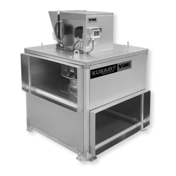
KUBAIR F400 ECOWATT
®
Smoke extract unit F400 - 120 (400°C 120 min)
VENTIDRIVE controllers
1/44
NT00000792-KUBAIR-F400-ECOWATT-VENTDRIVE-AN-220314
ENGLISH
Advertisement
Table of Contents

Related Manuals for ViM KUBAIR F400 ECOWATT


Summary of Contents for ViM KUBAIR F400 ECOWATT
- Page 1 INSTALLATION | CONNECTION| COMMISSIONING | MAINTENANCE | I S O 9 0 0 1 ISO 14001 Q u a l i t é Environnement AFNOR CERTIFICATION AFNOR CERTIFICATION KUBAIR F400 ECOWATT ® Smoke extract unit F400 - 120 (400°C 120 min) VENTIDRIVE controllers 1/44 NT00000792-KUBAIR-F400-ECOWATT-VENTDRIVE-AN-220314 ENGLISH...
-
Page 2: Table Of Contents
5.7 CAV constant airflow mode ....................38 COP constant pressure mode ....................39 MAINTENANCE..........................41 Maintenance frequency ......................41 Spare parts KUBAIR F400 ECOWATT ® ................42 WASTE MANAGEMENT ........................42 Treatment of Packagings and non dangerous wastes ............42 Treatment of a Professional WEEE ..................42... -
Page 3: General
® Smoke extract unit KUBAIR F400 ECOWATT are intended for smoke extraction and ventilation applica- tions in residential buildings, tertiary buildings, industrial buildings and professional kitchens: •... -
Page 4: Product Presentation
In any case, maker is not responsible for transformed material, even partially repaired. PRODUCT PRESENTATION EC Certificate F400 -120 N° 1812-CPR-0040, according to European Standard NF EN 12101-3 Approved F400 120 (400°C 120 min) • KUBAIR F400 ECOWATT CC : complete ® unit with multi-directional suction plenum, with horizontal or vertical axis motor. -
Page 5: Installation
- VENTIDRIVE controller 3 phases power supply 400V 50/60Hz controller input for sizes 500 up to 710. • Thermal protection fitted within the controller. Controller supplied as an accessory for KUBAIR F400 ECOWATT ® • ETDZ A: Stand-alone remote touch ModBus control for controlling 1 unit. -
Page 6: Summary Charts Of Assembly And Accessories
KUBAIR F400 ECOWATT ® Assembly with vertical motor axis(*) (*) The unit with vertical motor axis must not be fitted with motor down. Dimensions (mm) Weight (kg) Size A BH BV BVC C G GC Naked Insulated Naked Insulated 355 627 695 327 645 263 559 606 790 660 31 50 315 102 826 1103 321... - Page 7 KUBZ 03 KUBZ 08 KUBZ 01 MV KUBZ 07 KUBZ 16 ® The TCDZ accessories on the diagram below can be used with the KUBAIR F400 ECOWATT MV with a vertical axis motor: (example below) KUBZ 12 KUBZ 17 KUBZ 12...
- Page 8 KUBAIR F400 ECOWATT ® with vertical axis motor TCDZ03 TCDZ08 TCDZ03 TCDZ 04 TCDZ 07 TCDZ 02 TCDZ 09 Optional accessory according to selection. 8/44 NT00000792-KUBAIR-F400-ECOWATT-VENTDRIVE-AN-220314...
-
Page 9: Accessories (Dimensions In Mm)
3.3 Accessories (dimensions in mm) MSDZ Circular flexible sleeve Ø F MSCZ Rectangular flexible sleeve KUBZ 01 Standard support for horizontal axis motor: This support allows to fix the unit onto the floor with the mo- tor in horizontal axis position. Reposition, on the 2 corners of the unit on the side opposite the motor, 2 of the fixings of the unit and replace the other 2 fixings on the unit by those supplied with the KUBZ01. These 4 fixings are screwed onto the unit with 16 self-drilling screws 4.8x12 supplied. - Page 10 KUBZ 06 Capot KUBAIR The motor cowl is used for external installations. It is screwed (screws supplied) onto the motor support panel. KUBZ 07 KUBZ 08 Rain guard with bird guard These guards are attached after the supplied plain flange (KUBZ 12) has been detached from the casing. KUBZ 11 Double suction plenum To be bolted under the casing, without any accessory...
- Page 11 Dimensions (mm) and weight (kg) MSDZ - MSCZ - KUBZ 02, 08, 12, 16 et 17 Weight KUBZ KUBZ KUBZ KUBZ KUBZ KUBZ Size ØF 559 263 197 194 160 400 670 631 297 216 213 160 450 670 711 326 233 234 160 500 670 768 338 240 249 160 560 670 10,6 10,5...
- Page 12 TCDZ 04 TCDZ 07 Straight, inclined and acoustic upstand According to DTU 43.1, it is possible to attach a TCDZ 03 TCDZ 09 energy-saving component (excluding TCDZ 09) which is placed inside the upstand. For any casing with an acoustic straight upstand (TCDZ 09), provide for a drop in pressure of 80 Pa.
-
Page 13: Handling
Accessory TCDZ 02 TCDZ 03 SILS TCDZ 04 TCDZ 07 (30°) TCDZ 09 TCDZ 08 Size Weight Weight Weight Weight Weight Weight Weight 355/400 23,0 300/500/700 11,0/15,5/20,0 11,2 34,0 450/500 37,0 300/500/700 13,5/19,0/25,0 14,8 51,0 10,5 45,0 300/500/700 20,5/29,5/38,0 24,2 65,5 12,2 11,0... -
Page 14: Electrical Connection
Detaching and re-assembling casing panels The smooth side panels are easy to detach by loosening their screws. They are repositioned in the same way. ELECTRICAL CONNECTION 4.1 Preliminary precautions Give the user the operating instructions for the unit and the installed accessories so that they can be consulted at any time. -
Page 15: Electrical Characteristics
50/60Hz power supply. The switch is used to isolate the unit from the electrical network in case of maintenance operations, not to pilot the unit on/off. Safety switch access The switch is located next to the controller. KUBAIR F400 ECOWATT ® VCHV-A - Pressure or airflow, in Motor controller COP and CAV units... - Page 16 Wiring of version with INTZ safety switch 1V15 Unit size 355 / 400 / 450 Unit size 500 / 630 with one-phase controller with 3 phases controller INTZ 15A INTZ 15 A Wiring of version with INTZ safety switch 1V22 Unit size 710 with 3 phases controller INTZ 22 A 16/44...
-
Page 17: Commissioning And Configuration Of Controllers
COMMISSIONING AND CONFIGURATION OF CONTROLLERS 5.1 Presentation of the VENTIDRIVE controller The ECM motor controller controls the motor according to an adjustment potentiometer on the controller, an external 0-10V signal or a setpoint given by GTC ModBus. 5.1.1 Controller terminal block Running status LED Factory- tted terminal block One-phase... - Page 18 5.1.2 Alarms and operating status indication LED indication An LED is present next to cable glands on the controller. Constant green LED: the supply voltage is connected. Green LED flashing: Modbus communication is active. Constant red LED: at least one critical alarm is active. Flashing red LED: a non-critical alarm is active. Consultation of alarms and operating status of the extractor by the remote controller ETDZ A (optional) The ETDZ A remote control is connected to the Modbus RJ12 "C"...
-
Page 19: Modbus Connection - Connection To A Bms
5.2 Modbus connection - Connection to a BMS In the case of a connection to a BMS, the Modbus connection allows, according to unit versions: – VAV variable airflow driving: ® • KUBAIR F400 ECOWATT - On / Off, - Speed adjustment, - Reading of registers. -
Page 20: Supported Modbus Commands
Communication parameters In the Holding Registers 0x03 : Read 0x06 : Writing a register 0x10 : Write several registers Register Address Function Value Resolution / Option Unit Fault value 4x0017 Modbus ID 1 to 247 Modbus 4x0018 0 to 200 response time 4x0020 Trial number... - Page 21 Register Address Function Range Active state 0x0014 Allow using Brake Chopper 0 - 1 1 = Allow BC 0x0014 Allow using Cooling Fan 0 - 1 1 = Allow Fan 0 = Voltage values from CCF 3 x 230V config 0x0016 0 - 1 1 = Fixed values for 3 x 230V 0 = Start @ 2V 0x0017...
- Page 22 5.3.3 Input Registers Available Input Registers are shown in tables below. Input Registers: 34 (R) 0x04: Read EC-config (PM) FC-config (AC) Register Address Function Range Resolution Unit Resolution Unit 3x0001 Drive Type 1000 - 65535 3x0002 AOC SW version 0 - 65535 0.01 0.01 3x0003...
- Page 23 Register 2Address Function Range Active state Unit 3x8202 8201 Char9 + Char10 0-65535 2 x ACSII Char 3x8203 8202 Char11 + Char12 0-65535 2 x ACSII Char 3x8204 8203 Char13 + Char14 0-65535 2 x ACSII Char 3x8205 8204 Char15 + Char16 0-65535 2 x ACSII Char 3x8206...
- Page 24 Common for EC (PM) & FC (AC) configuration Register Address Function Range / Value Resolution / Option Unit 4x0024 Parity None Even 4x0025 Stop Bits INVALID DigIn1 config 4x0026 Disabled Start/stop AlarmReset MB_IDs_2 Invert 0-10V (open = inverted) Rotation Firemode Motor Overheat Invert 0-10V (open = not inverted) Motor output off...
- Page 25 Common for EC (PM) & FC (AC) configuration Register Address Function Range / Value Resolution / Option Unit DigIn3 config (IOM) 4x0031 Disabled Start/stop AlarmReset Disabled Invert 0-10V (open = inverted) Rotation Firemode Invert 0-10V (open = not inverted) Motor output off Modbus Disable DigIn4 config (IOM) 4x0032 Disabled...
- Page 26 Common for EC (PM) & FC (AC) configuration Register Address Function Range / Value Resolution / Option Unit IO_Opt2 config (IOM) 4x0034 Disabled RunningStart Output AlarmOut Output RunningSpin Output Set output status via coil Output stat 24 Single Error Alarm Output Disabled Start/Stop Input AlarmReset...
-
Page 27: Relay Operation
5.4 Relay operation Max 1 A at 30 VDC and 24 VAC. The Output 1 relay is a run relay. The relay switches when the run signal is given. Output 2 is a fault relay. The relay switches when the motor stops after 5 restart attempts. CONTROLLER TERMINALS Fault or power o indicator... -
Page 28: Smoke Extraction Operation
5.5 Smoke extraction operation The KUBAIR F400 ECOWATT® is approved for extraction of hot gases and smoke in the event of a fire. This mode of operation is automatic and does not require any setting: In the case of extraction of gas at a temperature > 200°C, the roof fan will automatically switch to high speed with its internal thermal protec- tions inhibited. -
Page 29: Vav Variable Airflow Mode
• By a SMTD switch (Min. speed/Speed 1/Speed 2/High speed with speeds 1 and 2 adjustable), • Airflow driven by Modbus BMS. Example of VAV slaving according to external temperature measurement: VAV slave according to outside temperature measurement VAV curve Extraction fan KUBAIR F400 ECOWATT® Sensor signal Air ow 1080 Q mini Q maxi T°... - Page 30 Factory wired Accessory wiring - ON/OFF CONTROLLER TERMINALS CONTROLLER TERMINALS +10V BCCA 1V POTENTIOMETER 0-10V Accessory not provided +10V Factory wired 0-10V Placed inside the controller terminal block SHUNT ON/OFF Instead of Factory wired the shunt Accessory wiring - Speed control CONTROLLER TERMINALS CONTROLLER TERMINALS Instead of the...
- Page 31 5.6.3 Speed adjustment Correspondence table between the fan speed and the input signal in VAV mode: KUBAIR F400 ECOWATT ® Input signal speed in rpm Potentiometer Voltage (V) at Value in the Modbus register 400/450 graduation terminal 5 Holding Registers 0...
- Page 32 5.6.4 Control of several KUBAIR ECOWATT ® From 1 to 32 KUBAIR ECOWATT® can be controlled from a single touch-sensitive remote control. Remote control reference: ETDZ R 692101. Modbus address configuration It is imperative to configure a unique Modbus address for each KUBAIR that will be controlled by the ETDZ R. To do this, use the ETDZ R touch screen remote control by wiring it to the RJ12-C port. Follow the instructions below: Menu USER SETTINGS...
- Page 33 Modbus connection between each KUBAIR ECOWATT and the touchscreen remot control ETDZ R ® to each other and to the remote control, use Modbus flat cable / To connect each KUBAIR ECOWATT ® telecommunication cable, 6 conductors, 30AWG/0.066 mm², with RJ12 connectors at each end. The RJ12 connector is on the back of the remote control. A rectangular notch in the blue cover of the controller allows the passage of flat cables.
- Page 34 CONTROL MODE START COMMAND ALARM RELAY Manual Manual Disabled Analog in > 1 V Analog in > 1V DV Relay 1 Analog in > 2 V Analog in > 2V DV Relay 2 Digital in Digital in Select Disabled, and then press the Select Manual, and then press the Select Manual, and then press the right arrow key...
- Page 35 Starting up the system To set a speed setpoint and turn on the system, follow the instructions below: Select a speed setpoint: ENTER VALUE SETPOINT RANGE : 0-100% Setpoint 0% Operation mode Const. speed Current speed _ _ _ % Current speed _ _ _ RPM Press on 0%...
- Page 36 Consultation of alarms The ETDZ R remote control provides precise information on the type of alarm. You can view and reset an alarm via the ETDZ R by following the instructions below: Warnings & alarms DV 3 Warnings & alarms RESET ALL RESET ALL WARNING/ALARM...
- Page 37 MODBUS SETTINGS CONNECTION Connection 2/2 DEVICES CONNECTED DV 1 DV 2 Press on Connection View connection status Login Ok Lost connection Return to the home screen by pressing the arrow in the upper left corner 3 times. Viewing the system status: Using the touchscreen remote control, you can check the system status.
-
Page 38: Cav Constant Airflow Mode
5.7 CAV constant airflow mode 5.7.1 Description In constant airflow operation, the VCHV-A located to the right of the INTZ safety switch on one side of the unit regulates the motor speed to achieve the desired airflow setpoint. The airflow setpoint is to be entered on the VCHV-A in m /h or m /hx1000 depending on the size of the unit. 5.7.2 Command wiring For Analog/Digital controls use cable with the following characteristics: • Sheath Ø: 6.8mm to 9mm •... -
Page 39: Cop Constant Pressure Mode
Follow the instructions below: SET.1 SET.6 The first digit flashes, press the up or down arrows 1.0.0.0 to enter the desired airflow setpoint. Press OK to move to the next digit SET.6 KUBAIR F400 ECOWATT K* coefficient Setpoint selected in* Max. setpoint ® 4 200 m 5 400 m 8 000 m /h x 1 000... - Page 40 SET.1 SET.3 The first digit flashes, press the up or down arrows 0100 to enter the desired setpoint in Pa. Press OK to move to the next digit SET.3 KUBAIR F400 ECOWATT Setpoint selected in* Max. setpoint ® 520 Pa 460 Pa 550 Pa 700 Pa...
-
Page 41: Maintenance
On / Off via Modbus In Coil Stat Bits 0x01 : Playback 0x05 : Writing a register Register Address Function Value Status 0 - OFF 0x0001 ON/OFF motor 0 - 1 1 - ON MAINTENANCE 6.1 Maintenance frequency Perform a periodical check based on the following indications: Unit/Item At commissioning Every 6 months minimum... -
Page 42: Waste Management
6.2 Spare parts KUBAIR F400 ECOWATT ® Model Code Designation MTTE KUBAIR ECOWATT ® 355 1 phase 230V motor KUBAIR F400 ECOWATT 355 1 phase 230V ® 646890 MTTE KUBAIR ECOWATT ® 400 1 phase 230V motor KUBAIR F400 ECOWATT 400 1 phase 230V ®... - Page 43 43/44 NT00000792-KUBAIR-F400-ECOWATT-VENTDRIVE-AN-220314...
- Page 44 Les prés de Mégy Sud – SOUDAN CS 60120 - 79401 ST MAIXENT L’ECOLE CEDEX Tél. : 05 49 06 60 38 ou 05 49 06 60 25 – Fax : 05 49 06 60 36 sav@vim.fr - www.vim.fr 44/44 NT00000792-KUBAIR-F400-ECOWATT-VENTDRIVE-AN-220314...
Need help?
Do you have a question about the KUBAIR F400 ECOWATT and is the answer not in the manual?
Questions and answers