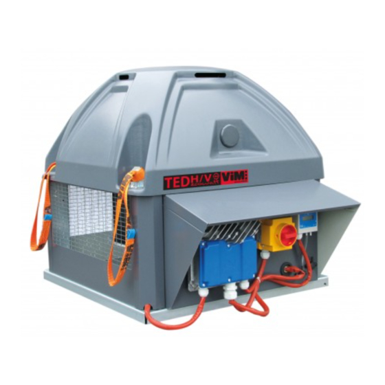
ViM TEDH F400 ECOWATT Technical Manual
Roof fan f400-120 (400c 120 min) ec motor
Hide thumbs
Also See for TEDH F400 ECOWATT:
- Technical manual (48 pages) ,
- Instruction manual (28 pages) ,
- Installation manual (24 pages)
Table of Contents
Advertisement
Quick Links
TECHNICAL MANUAL
INSTALLATION | CONNECTION| COMMISSIONING | MAINTENANCE |
I S O 9 0 0 1
ISO 14001
Q u a l i t é
Environnement
AFNOR CERTIFICATION
AFNOR CERTIFICATION
TEDH F400 ECOWATT
®
TEDV F400 ECOWATT
®
Roof Fan F400-120 (400°C 120 min)
EC Motor
VENTIDRIVE Controller
1/60
NT00000658-TEDH-V-F400-ECOWATT-AN-210609
ENGLISH
Advertisement
Table of Contents

Related Manuals for ViM TEDH F400 ECOWATT


Summary of Contents for ViM TEDH F400 ECOWATT
- Page 1 INSTALLATION | CONNECTION| COMMISSIONING | MAINTENANCE | I S O 9 0 0 1 ISO 14001 Q u a l i t é Environnement AFNOR CERTIFICATION AFNOR CERTIFICATION TEDH F400 ECOWATT ® TEDV F400 ECOWATT ® Roof Fan F400-120 (400°C 120 min) EC Motor VENTIDRIVE Controller...
-
Page 2: Table Of Contents
SUMMARY GENERAL ............................3 Disclaimers ..........................3 Safety instructions ........................3 Acceptance – Storage ......................3 Warranty ........................... 4 PRODUCT PRESENTATION ......................4 INSTALLATION ..........................5 Dimensions and weights......................5 Handling ........................... 6 Summary charts of assembly and accessories ................ 7 Removing the caps ......................... -
Page 3: General
GENERAL 1.1 Disclaimers This product has been manufactured according to rigorous technical rules of safety in conformity with EC standards. The EC declaration may be downloaded from the Internet site (address given on the last page). Before installing and using this product, carefully read these instructions, which contain important indica- tions for your safety and the user’s safety during the installation, commissioning and maintenance of this product. -
Page 4: Acceptance - Storage
• 6 sizes : 355 / 400 / 450 / 500 / 630 / 710 Certification EC Certificate F400-120 No. 1812-CPR-1085, according to European Standard NF EN 12101-3. Approved F400 120 (400°C 120min). Construction • TEDH F400 ECOWATT : horizontal discharge through 2 or 3 sides. ® • TEDV F400 ECOWATT : vertical discharge through 2 or 3 sides. -
Page 5: Installation
INSTALLATION 3.1 Dimensions and weights TEDH F400 ECOWATT TEDV F400 ECOWATT ® ® Ø D Ø D Fixation E Fixation E Model Weight H (kg) Weight V (kg) 289,1 325,8 1051 366,5 1070 407,3 1045 1279 513,1 1089 1223 1489... -
Page 6: Handling
WARNING: Do not leave the slings on the product once it is installed. VIM shall be relieved of any responsibility in case these slings are not properly used. WARNING: Do not lift the product by holding it by the plastic cover cap. -
Page 7: Summary Charts Of Assembly And Accessories
3.3 Summary charts of assembly and accessories TEDH F400 ECOWATT TEDV F400 ECOWATT ® ® KRVT TCDZ 14 TCDZ 15 POPM (TEDH) (TEDV) (TEDH) TDCZ06 TCDZ03 TCDZ05* TCDZ03 TCDZ08 TCDZ01 TCDZ 04 TCDZ 07 TCDZ 02 TCDZ 09 * : Some adaptation plate diameters are not compatible with the following accessories: TCDZ 02, 04, 07 and 08 (see § "3.3.4 Adaptation plate : TCDZ 05", page 9). - Page 8 3.3.1 Standard support: TCDZ 01 This assembly does not allow using an energy save flap or an adaptation plate. Make sure that the duct can withstand the roof fan weight. • Install the 4 angle brackets B and the 2 hose clamps C on the duct. • Install the seal A on the duct’s free edge. • Put the roof fan on the duct by centring it cor- rectly.
- Page 9 3.3.4 Adaptation plate : TCDZ 05 The adaptation plate allows connecting roof fan to a circular duct. Since it is designed to make the air connection, it is not supposed to withstand roof fan weight. This is incompatible with the use of the energy saver flap TCDZ 03 and the roof adapter with sound attenuator TCDZ 09.
- Page 10 • Glue the foam seal on the support. • Position the roof fan on the kit (pay particular Foam attention to the plate’s direction). seal • Screw the 2 HM8x20 screws in the hinge’s crimped nuts. • Tie up the free chain extremity to the roof fan plate with an HM8x16 bolt supplied.
- Page 11 3.3.7 Horizontal and inclined roof adapters : TCDZ 04, TCDZ 07 ou 09 It is possible to associate an energy save flap TCDZ 03 or an adaptation plate TCDZ 05 (except for TCDZ 09) placed inside the insert. For roof fan with acoustic straight insert (TCDZ 09), take into account a 80Pa pressure drop. TCDZ 04 TCDZ 07 TCDZ 09 Weight (kg) Accessory Unit size...
- Page 12 3.3.9 Overpressure flaps TCDZ 12, TCDZ 14, TCDZ 15 Overpressure flaps. Ensure a good air tightness and water tightness when the unit is stopped. TCDZ 12 : fitted option on the TEDV unit delivered. Use as much TCDZ 12 as exhaust sides. TCDZ 14 : accessory to set on a TEDV unit already delivered. Use as much TCDZ 14 as exhaust sides. TCDZ 15 : accessory to set on a TEDH unit already delivered. Use as much TCDZ 15 as exhaust sides. Setting of a TCDZ 15 on a TEDH Setting of a TCDZ 14 on a TEDV •...
-
Page 13: Removing The Caps
3.4 Removing the caps To remove the caps : • Raise the cap slightly upward. • Pull the cap outward. The plastic top cap does not have to be removed. 3.5 Mounting the roof fan The support surface, which will support the roof fan base, must also be as flat as possible (embedding frame or roof adapter supplied on request). A foam seal, or equivalent (not supplied), is recommended between the support surface and the roof fan base. -
Page 14: Mounting The Roof Fan Deflectors
3.6 Mounting the roof fan deflectors 3.6.1 Vertical discharge kit KRVT ® Allows transforming a horizontal roof fan TEDH F400 ECOWATT into a vertical roof fan TEDV F400 ® ECOWATT It is recommended to wear protective gloves to handle the various elements. -
Page 15: Electrical Connection
3.6.2 A discharge surface closing plate kit POPM On TEDH and TEDV F400 ECOWATT ® , allows to prevent the discharge of air and direct splashings on the wall. Take into account pressure drops here below: PdC 1 POPM (Pa) Qv (m 4000 8000... -
Page 16: Electrical Characteristics
Use in smoke extraction Refer to standard NF S 61-932 for connection and installation. Use high temperature cable type CR1-C1. The cable must be protected against UV radiation. Electrical cables and accessories must be dimensioned in accordance with article 433-3. of standard NF C 15-100: "the cross-section of the conductors of the line is determined by a current admissible equal to 1.5 times the nominal motor current". -
Page 17: Wiring Of Intz Safety Switch
4.3 Wiring of INTZ safety switch Safety switch delivered factory wired and mounted. Note: the safety switch is sized to be used in smoke extract application for a 400V three-phases or 230V single-phase 50/60Hz power supply. The switch is used to isolate the unit from the electrical network in case of maintenance operations, not to pilot the unit on/off. - Page 18 Wiring of version with INTZ safety switch 1V15 Unit size 355 / 400 / 450 Unit size 500 / 630 with compacto controller with Invento S controller INTZ 15A INTZ 15 A Wiring of version with INTZ safety switch 1V22 Unit size 710 with Invento S controller INTZ 22 A 18/60...
-
Page 19: Commissioning And Configuration Of One-Phase Controllers Sizes 355/400/450
COMMISSIONING AND CONFIGURATION OF ONE-PHASE CONTROLLERS SIZES 355/400/450 5.1 Presentation of the VENTIDRIVE single-phase controller The ECM motor controller controls the motor according to an adjustment potentiometer on the controller, an external 0-10V signal or a setpoint given by GTC ModBus. 5.1.1 Controller terminal block Running status LED Factory- tted terminal block... - Page 20 5.1.2 Alarms and operating status indication LED indication An LED is present next to cable glands on the controller. Constant green LED: the supply voltage is connected. Green LED flashing: Modbus communication is active. Constant red LED: at least one critical alarm is active. Flashing red LED: a non-critical alarm is active. Consultation of alarms and operating status of the extractor by the remote controller ETDZ A (optional) The ETDZ A remote control is connected to the Modbus RJ12 "C"...
-
Page 21: Modbus Connection - Connection To A Bms
5.2 Modbus connection - Connection to a BMS In the case of a connection to a BMS, the Modbus connection allows, according to unit versions: – VAV variable airflow driving: ® • TEDH/V F400 ECOWATT - On / Off, - Speed adjustment, - Reading of registers. – Adjustment to CAV constant airflow or COP constant pressure: ®... -
Page 22: Supported Modbus Commands
Communication parameters In the Holding Registers 0x03 : Read 0x06 : Writing a register 0x10 : Write several registers Register Address Function Value Resolution / Option Unit Fault value 4x0017 Modbus ID 1 to 247 Modbus 4x0018 0 to 200 response time 4x0020 Trial number... - Page 23 Register Address Function Range Active state 0x0014 Allow using Brake Chopper 0 - 1 1 = Allow BC 0x0014 Allow using Cooling Fan 0 - 1 1 = Allow Fan 0 = Voltage values from CCF 3 x 230V config 0x0016 0 - 1 1 = Fixed values for 3 x 230V 0 = Start @ 2V 0x0017...
- Page 24 5.3.3 Input Registers Available Input Registers are shown in tables below. Input Registers: 34 (R) 0x04: Read EC-config (PM) FC-config (AC) Register Address Function Range Resolution Unit Resolution Unit 3x0001 Drive Type 1000 - 65535 3x0002 AOC SW version 0 - 65535 0.01 0.01 3x0003...
- Page 25 Register 2Address Function Range Active state Unit 3x8202 8201 Char9 + Char10 0-65535 2 x ACSII Char 3x8203 8202 Char11 + Char12 0-65535 2 x ACSII Char 3x8204 8203 Char13 + Char14 0-65535 2 x ACSII Char 3x8205 8204 Char15 + Char16 0-65535 2 x ACSII Char 3x8206...
- Page 26 Continued table Common for EC (PM) & FC (AC) configuration Register Address Function Range / Value Resolution / Option Unit 4x0017 Modbus ID 1 - 247 4x0018 ModbusResponseDelay 0 - 200 4x0020 Number of retries -1 - 100 4x0022 CommTimeout 0 - 240 Sec.
- Page 27 Common for EC (PM) & FC (AC) configuration Register Address Function Range / Value Resolution / Option Unit DigIn3 config (IOM) 4x0031 Disabled Start/stop AlarmReset Disabled Invert 0-10V (open = inverted) Rotation Firemode Invert 0-10V (open = not inverted) Motor output off Modbus Disable DigIn4 config (IOM) 4x0032 Disabled...
- Page 28 Common for EC (PM) & FC (AC) configuration Register Address Function Range / Value Resolution / Option Unit IO_Opt2 config (IOM) 4x0034 Disabled RunningStart Output AlarmOut Output RunningSpin Output Set output status via coil Output stat 24 Single Error Alarm Output Disabled Start/Stop Input AlarmReset...
-
Page 29: Relay Operation
5.4 Relay operation Max 1 A at 30 VDC and 24 VAC. The Output 1 relay is a run relay. The relay switches when the run signal is given. Output 2 is a fault relay. The relay switches when the motor stops after 5 restart attempts. CONTROLLER TERMINALS Fault or power o indicator... -
Page 30: Smoke Extraction Operation
5.5 Smoke extraction operation The TEDH/V F400 ECOWATT® is approved for extraction of hot gases and smoke in the event of a fire. This mode of operation is automatic and does not require any setting: In the case of extraction of gas at a temperature > 200°C, the roof fan will automatically switch to high speed with its internal thermal protec- tions inhibited. -
Page 31: Vav Variable Airflow Mode
5.6 VAV variable airflow mode 5.6.1 Description In variable speed operation, the controller pilots the speed of the roof fan linearly. The controller will vary the speed of the roof fan between 200 rpm (min. speed), and its maximum speed in proportion to the signal sent by the external sensor. If the display is present on the roof fan, it will show you the airflow in m The speed adjustment can be done in different ways: •... - Page 32 Factory wired Accessory wiring - ON/OFF CONTROLLER TERMINALS CONTROLLER TERMINALS +10V BCCA 1V POTENTIOMETER 0-10V Accessory not provided +10V Factory wired 0-10V Placed inside the controller terminal block SHUNT ON/OFF Instead of Factory wired the shunt Accessory wiring - Speed control CONTROLLER TERMINALS CONTROLLER TERMINALS Instead of the...
- Page 33 5.6.3 Speed adjustment Correspondence table between the fan speed and the input signal in VAV mode: TEDH/V F400 ECOWATT ® Input signal in rpm Potentiometer Voltage (V) at Value in the Modbus register 400/450 graduation terminal 5 Holding Registers 0 2 000 4 000 1180...
- Page 34 5.6.4 Control of several single-phase TEDH/V ECOWATT single-phase VAV ® From 1 to 32 TEDH/V ECOWATT ® can be controlled from a single touch-sensitive remote control. Remote control reference: ETDZ R 692101. Modbus address configuration It is imperative to configure a unique Modbus address for each TEDH/V that will be controlled by the ETDZ R. To do this, use the ETDZ R touch screen remote control by wiring it to the RJ12-C port. Follow the instructions below: Menu USER SETTINGS...
- Page 35 Modbus connection between each TEDH/V ECOWATT and the touchscreen remot control ETDZ R ® to each other and to the remote control, use Modbus flat cable / To connect each TEDH/V ECOWATT ® telecommunication cable, 6 conductors, 30AWG/0.066mm², with RJ12 connectors at each end. The RJ12 connector is on the back of the remote control. A rectangular notch in the blue cover of the controller allows the passage of flat cables.
- Page 36 CONTROL MODE START COMMAND ALARM RELAY Manual Manual Disabled Analog in > 1 V Analog in > 1V DV Relay 1 Analog in > 2 V Analog in > 2V DV Relay 2 Digital in Digital in Select Disabled, and then press the Select Manual, and then press the Select Manual, and then press the right arrow key...
- Page 37 Starting up the system To set a speed setpoint and turn on the system, follow the instructions below: Select a speed setpoint: ENTER VALUE SETPOINT RANGE : 0-100% Setpoint 0% Operation mode Const. speed Current speed _ _ _ % Current speed _ _ _ RPM Press on 0%...
- Page 38 Consultation of alarms The ETDZ R remote control provides precise information on the type of alarm. You can view and reset an alarm via the ETDZ R by following the instructions below: Warnings & alarms DV 3 Warnings & alarms RESET ALL RESET ALL WARNING/ALARM...
- Page 39 MODBUS SETTINGS CONNECTION Connection 2/2 DEVICES CONNECTED DV 1 DV 2 Press on Connection View connection status Login Ok Lost connection Return to the home screen by pressing the arrow in the upper left corner 3 times. Viewing the system status: Using the touchscreen remote control, you can check the system status.
-
Page 40: Cav Constant Airflow Mode
5.7 CAV constant airflow mode 5.7.1 Description In constant airflow operation, the VCHV-A located to the right of the INTZ safety switch on one side of the unit regulates the motor speed to achieve the desired airflow setpoint. The airflow setpoint is to be entered on the VCHV-A in m /h or m /hx1000 depending on the size of the unit. 5.7.2 Command wiring For Analog/Digital controls use cable with the following characteristics: • Sheath Ø: 6.8mm to 9mm •... -
Page 41: Cop Constant Pressure Mode
5.7.3 Adjusting the airflow setpoint The airflow setpoint setting is to be set on the VCHV-A controller present on the right side of the controller. The VCHV-A is mounted and wired at the factory. The adjustment keys of the VCHV-A are located inside the housing under the cover. Press the snap lock under the housing next to the pressure taps to open the case. - Page 42 For Modbus control use cable with the following characteristics: • On terminal block terminals 1,2,3: - Sheath Ø: 6.8mm to 9mm • Strand cross-section: 0.7mm² to 1mm² • Recommended minimum stripping: 10mm On RJ12 connectors: • Telecommunication cable/flat cable, 6-core, unshielded, 30 AWG/0.066 mm² Maximum recommended length for Modbus communication: 100m, for longer lengths see § "5.2 Modbus connection - Connection to a BMS", page 21 Factory wired Accessory wired - ON/OFF...
-
Page 43: Commissioning And Configuration Of Three-Phases Controllers Sizes 500/630/710
On / Off via Modbus In Coil Stat Bits 0x01 : Playback 0x05 : Writing a register Register Address Function Value Status 0 - OFF 0x0001 ON/OFF motor 0 - 1 1 - ON COMMISSIONING AND CONFIGURATION OF THREE-PHASES CONTROLLERS SIZES 500/630/710 6.1 Presentation of the INVENTO three-phases controller The ECM motor controller controls the motor according to an adjustment potentiometer on the controller,... - Page 44 Terminal strip for control connection The various control functions are described in the manual Factory-made motor connection terminal block It is imperative that the order of the U-V-W cables is observed Factory- tted INTZ safety switch terminal strip Three-phases Terminal block accessible KUBAIR 500 under the cover by 6 TX20 screws KUBAIR 630...
-
Page 45: Modbus Connection - Connection To A Bms
This state is normal during controller operation and should always be present. When disconnecting the controller from power, wait until the LEDs stop flashing before reconnecting. Controller operating instructions can be provided by VIM Service. Troubleshooting In the event of a fault, an initial restart operation after a 5-minute power failure may allow the controller to reset itself. - Page 46 Linear network topology Invento 01 Invento 02 Invento 03 5 6 7 8 5 6 7 8 5 6 7 8 Derivation RX / TX + Converter USB - RS485 RX / TX - Termination 120Ω 1 nF Segment BUS network topology Invento 01 Invento 02 Invento 03...
- Page 47 Speed tr/min Power Input An1 0,01 Input An2 0,01 The communication protocol and the Modbus exchange table are available on our website www.vim.fr NT00000673-KUBAIR-TED-REGULATION. For all other information on the setting of Modbus, contact the After-Sales service department. 47/60 NT00000658-TEDH-V-F400-ECOWATT-AN-210609...
-
Page 48: Relay Operation
6.3 Relay operation Replaces the use of a BDEZ type pressure switch Ventilation fault TEDH/V F400 ECOWATT three-phases ® INVENTO Relay fault 17 18 19 Ventilation fault Normal running indicator light indicator light Power supply Regardless of the principle of operation of the roof fan, the relay operates in the following manner: Unit status Relay status** Invento... -
Page 49: Vav Variable Airflow Mode
6.5 VAV variable airflow mode 6.5.1 Description In variable speed operation, the controller pilots the speed of the roof fan linearly. The controller will vary the speed of the roof fan between 200 rpm (min. speed), and its maximum speed in proportion to the signal sent by the external sensor. If the display is present on the roof fan, it will show you the airflow in m The speed adjustment can be done in different ways: •... - Page 50 Factory wired Accessory wiring - ON/OFF CONTROLLER TERMINALS CONTROLLER TERMINALS 9 10 11 Instead of BCCA 1V the shunt Accessory not provided SHUNT ON/OFF Factory wired POTENTIOMETER Factory wired Placed inside the controller terminal block Accessory wiring - Speed control CONTROLLER TERMINALS CONTROLLER TERMINALS *24Vdc -...
-
Page 51: Cav Constant Airflow Mode
6.5.3 Speed adjustment Correspondence table between the fan speed and the input signal in VAV mode: TEDH/V F400 ECOWATT in rpm Input signal ® Potentiometer Voltage (V) at Value in the Modbus register graduation terminal 10 Holding Registers 0 2 000 4 000 6 000 1240... - Page 52 6.6.2 Wiring of controls For Analog/Digital controls use cable with the following characteristics: • Sheath Ø: 6mm to 12mm • Strand cross-section: 0.7mm² to 1mm². • Recommended minimum stripping: 10mm • Maximum recommended length: 30m For Modbus control use cable with the following characteristics: •...
- Page 53 6.6.3 Airflow setpoint setting By potentiometer, remote control type CVF or 0-10V source. The potentiometer placed inside the controller allows you to modify the airflow setpoint. The setpoint can be given by the remote control type CVF or a 0-10V source. The display shows you the measured airflow. The display shows m /h x 1000. Airflow (m Potentiometer graduation 3950...
-
Page 54: Cop Constant Pressure Mode
TEDH/V F400 ECOWATT TEDH/V F400 ECOWATT TEDH/V F400 ECOWATT ® ® ® Setpoint register 0 1000 3 950 m 6 770 m 7480 m 2000 5 590 m 9 570 m 10 580 m 3000 6 850 m 11 720 m 12 950 m 4000 7 910 m... - Page 55 Factory wired CONTROLLER TERMINALS CONTROLLER TERMINALS 9 10 11 12 13 14 15 16 9 10 11 12 13 14 15 16 Shunt ON/OFF Shunt ON/OFF Factory wired Factory wired Potentiometer Potentiometer PTHV-A Factory wired Factory wired Factory wired Yellow Black 1 2 3 4 SW1 Green...
- Page 56 6.7.3 Adjusting the pressure set point By potentiometer, CVF type remote control or 0-10V output. By default the roof fan is set to obtain the pressure in bold in the table. The potentiometer in the controller allows you to change the pressure set point. The set point can be given by the CVF type remote control or a 0-10V output.
-
Page 57: Maintenance
MAINTENANCE 7.1 Maintenance frequency Perform a periodical check based on the following indications: Unit/Item At commissioning Every 6 months minimum Check the direction of rotation and the absence Clean if necessary, check the absence of of friction between the moving parts and the fixed Turbine friction between the moving parts and the fixed parts parts Check the connections, especially those to earth Retighten the terminals if necessary, check... -
Page 58: Spare Parts
7.2 Spare parts Model Code VIM Designation ® TEDH/V F400 ECOWATT 355 & 400 071312 Cap TED 355-400 RAL 7024 ABS-PMMA ® TEDH-V F400 ECOWATT 450 & 500 071313 Cap TED 450-500 RAL 7024 ABS-PMMA ® TEDH/V F400 ECOWATT 071314 Cap TED 560-630 RAL 7024 ABS-PMMA ®... -
Page 59: Waste Management
WASTE MANAGEMENT 8.1 Treatment of Packagings and non dangerous wastes The packagings (unconsigned pallets, cartons, films, wooden boxes) and other non dangerous wastes must be made reusable by an approved service provider. It is strictly prohibited to burn, bury or dump them in nature. 8.2 Treatment of a Professional WEEE This product must not be dumped or treated with household refuse, but must be deposited in an appro- priate collection point for waste electrical and electronic equipment (WEEE). - Page 60 Les prés de Mégy Sud – SOUDAN CS 60120 - 79401 ST MAIXENT L’ECOLE CEDEX Tél. : 05 49 06 60 38 ou 05 49 06 60 25 – Fax : 05 49 06 60 36 sav@vim.fr - www.vim.fr 60/60 NT00000658-TEDH-V-F400-ECOWATT-AN-210609...
Need help?
Do you have a question about the TEDH F400 ECOWATT and is the answer not in the manual?
Questions and answers