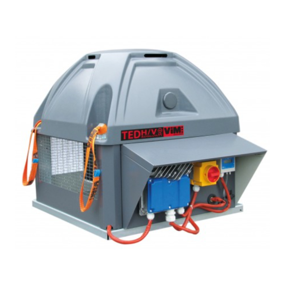
ViM TEDH F400 ECOWATT Technical Manual
Roof fan f400-120 (400 c 120 min) ec motor
Hide thumbs
Also See for TEDH F400 ECOWATT:
- Technical manual (60 pages) ,
- Instruction manual (28 pages) ,
- Installation manual (24 pages)
Table of Contents
Advertisement
Quick Links
T EC HNIC A L M A NU A L
INST A LLA T IO N | C O NNEC T IO N| C O M M ISSIO NING | M A INT ENA NC E |
I S O 9 0 0 1
ISO 14001
Q u a l i t é
Environnement
AFNOR CERTIFICATION
AFNOR CERTIFICATION
®
T ED H F 4 0 0 EC O W A T T
®
T ED V F 4 0 0 EC O W A T T
Roof Fan F400-120 (400°C 120 min)
EC Motor
NT-50905701-TEDH-TEDV-F400-ECOWATT-AN-191025
Advertisement
Table of Contents

Related Manuals for ViM TEDH F400 ECOWATT


Summary of Contents for ViM TEDH F400 ECOWATT
- Page 1 T EC HNIC A L M A NU A L INST A LLA T IO N | C O NNEC T IO N| C O M M ISSIO NING | M A INT ENA NC E | I S O 9 0 0 1 ISO 14001 Q u a l i t é...
-
Page 2: Table Of Contents
SOMMAIRE GENER A L ............................3 Disclaimers .......................... -
Page 3: Gener A L
® ® The TEDH F400 ECOWATT and TEDV F400 ECOWATT centrifugal backward roof fans are intended for smoke extraction and ventilation applications in residential buildings, tertiary buildings, industrial buildings and professional kitchens: •... -
Page 4: Acceptance - Storage
The equipment is warranted for twelve (12) months – Parts only – from date of manufacture. VIM agrees to replace parts or the equipment whose operation is recognised defective by our departments, excluding all damages or penalties, such as operating losses, commercial prejudice, or other intangible or indirect losses. -
Page 5: Inst A Lla T Io N
T ED EC O W A T T ® t y p e R u n n i n g m o d e El e c t r i c a l a c c e s s o r i e s * V A V Manual - Internal potentiometer Included in the controller... -
Page 6: Handling
W A R NING: Do not leave the slings on the product once it is installed. VIM shall be relieved of any responsibility in case these slings are not properly used. W A R NING: Do not lift the product by holding it by the plastic cover cap. -
Page 7: Mounting Roof Fan Accessories
3 . 3 M o u n t i n g r o o f f a n a c c e s s o r i e s T ED H F 4 0 0 EC O W A T T ®... - Page 8 3 . 3 . 1 St a n d a r d s u p p o r t : T C D Z 0 1 This assembly does not allow using an energy save flap or an adaptation plate. Make sure that the duct can withstand the roof fan weight. • Install the 4 angle brackets B and the 2 hose clamps C on the duct.
- Page 9 3 . 3 . 4 A d a p t a t i o n p l a t e : T C D Z 0 5 The adaptation plate allows connecting roof fan to a circular duct. Since it is designed to make the air connection, it is not supposed to withstand roof fan weight.
- Page 10 • Glue the foam seal on the support. Foam • Position the roof fan on the kit (pay particular seal attention to the plate’s direction). • Screw the 2 HM8x20 screws in the hinge’s crimped nuts. • Tie up the free chain extremity to the roof fan plate with an HM8x16 bolt supplied.
- Page 11 3 . 3 . 7 Ho r i z o n t a l a n d i n c l i n e d r o o f a d a p t e r s : T C D Z 0 4 , T C D Z 0 7 o u 0 9 It is possible to associate an energy save flap TCDZ 03 or an adaptation plate TCDZ 05 (except for TCDZ 09) placed inside the insert.
- Page 12 3 . 3 . 9 Overpressure flaps TCDZ 12, TCDZ 14, TCDZ 15 Overpressure flaps. Ensure a good air tightness and water tightness when the unit is stopped. TCDZ 12 : fitted option on the TEDV unit delivered. Use as much as exhaust sides. TCDZ 14 : accessory to set on a TEDV unit already delivered. Use as much TCDZ 14 as exhaust sides. TCDZ 15 : accessory to set on a TEDH unit already delivered. Use as much TCDZ 15 as exhaust sides. Se t t i n g o f a T C D Z 1 5 o n a T ED H Se t t i n g o f a T C D Z 1 4 o n a T ED V •...
-
Page 13: Removing The Caps
3 . 4 R e m o v i n g t h e c a p s To remove the caps : • Raise the cap slightly upward. • Pull the cap outward. The plastic top cap does not have to be removed. 3 . -
Page 14: Mounting The Roof Fan Deflectors
3 . 6 . 1 V e r t i c a l d i s c h a r g e k i t K R V T ® Allows transforming a horizontal roof fan TEDH F400 ECOWATT into a vertical roof fan TEDV F400 ®... -
Page 15: Elec T R Ic A L C O Nnec T Io
3 . 6 . 2 A d i s c h a r g e s u r f a c e c l o s i n g p l a t e k i t P O P M ®... -
Page 16: Electrical Characteritics
4 . 2 El e c t r i c a l c h a r a c t e r i t i c s P . No m I. No m . ( A ) I. No m . ( A ) El e c t r i c a l p r o t e c t i o n M o d e l INT Z... -
Page 17: C O M M Issio Ning A Nd Set T Ing
W i r i n g o f v e r s i o n w i t h INT Z s a f e t y s w i t c h 1 V 2 2 U n i t s i z e 7 1 0 w i t h In v e n t o S c o n t r o l l e r INTZ 22 A C O M M ISSI O NING A N D SE T T ING 5 . -
Page 18: Controllers
*If the control unit detects a fault more than once, notably a phase problem twice, the roof fan will not restart automatically. (**) NO.: normally open, NC: normally closed. Switch off the power supply for 5 min and restart the roof fan. If the problem persists, it is possible to identify the nature of the problem in the registers of the Modbus. The controller operating manual is avail- able for more information on www.vim.fr. 18/48 NT-50905701-TEDH-TEDV-F400-ECOWATT-AN-191025 ENGLISH... - Page 19 1 = Stop (motor stop) temperature of the controller reached power HW over current 1 = IGBT software current protection 1 = Weakening of the active field FLW enabled System error 1= Machine error Refer to the controller operating manual if necessary (available on www.vim.fr). 19/48 NT-50905701-TEDH-TEDV-F400-ECOWATT-AN-191025 ENGLISH...
- Page 20 5 . 2 . 4 M o d b u s c o n n e c t i o n - C o n n e c t i o n t o a B M S In the case of a connection to a BMS, the Modbus connection, present in standard, allows: Single phase or 3-phase - Control of the VAV variable flow rate: •...
- Page 21 Compacto 1 Compacto 2 Compacto 3 20 21 22 23 20 21 22 23 20 21 22 23 RX / TX + Terminaison 120Ω 1 nF Convertisseur USB - RS485 RX / TX - Segment Invento 01 Invento 02 Invento 03 Dérivation RX / TX + Convertisseur USB - RS485...
- Page 22 P a r i t y NONE * For additional information refer to the roof fan controller manual (available on www.vim.fr). 5 . 2 . 6 In p u t r e g i s t e r t a b l e The "Input Register"...
-
Page 23: Operation For Smoke Extraction
5 . 3 O p e r a t i o n f o r s m o k e e x t r a c t i o n The TED F400 ECOWATT® is approved for extraction of hot gases and smoke in the event of a fire. This mode of operation is automatic and does not require any setting: In the case of extraction of gas at a tem- perature >... - Page 24 Example of slaving and VAV regulation according to measurement of the outside temperature: V A V s l a v e d a c c o r d i n g t o m e a s u r e m e n t o f t h e o u t s i d e V A V w i t h r e g u l a t i o n a c c o r d i n g t o t h e d e v i a t i o n b e t w e e n t e m p e r a t u r e t h e s e t p o i n t / e x t e r n a l m e a s u r e m e n t...
- Page 25 W i r i n g f o r a c c e s s o r i e s n o t s u p p l i e d MODBUS BDRA Controller Controller 16 17 20 21 Factory tted Thermo switch and wired ON / OFF...
- Page 26 W i r i n g f o r m a n u a l t w o - s p e e d c o n t r o l 0 - LS- HS i n s t a l l a t i o n d i a g r a m , w i t h a d j u s t a b l e LS The LS is defined by the potentiometer of the controller, and the HS is the speed of the roof fan on a control signal of 10V.
- Page 27 W i r i n g f o r r e g u l a t i o n a c c o r d i n g t o t h e d e v i a t i o n b e t w e e n t h e s e t p o i n t / e x t e r n a l m e a s u r e m e n t 0 - 10V OUTPUT Controller Controller...
-
Page 28: Single-Phase - Cav Constant Flow Rate Control
Sp e e d a d j u s t m e n t 0 / LS / HS ( a d j u s t a b l e LS) The adjustment can be done by a BCCA type 2S 0 / LS / HS switch. The low speed is adjusted with the controller potentiometer. - Page 29 5 . 6 . 1 W i r i n g CAV type factory assembly and wiring. C o n n e c t i o n o f t h e p o w e r s u p p l y t o t h e INT Z s w i t c h t o b e d o n e b y t h e c u s t o m e r .
- Page 30 5 . 6 . 2 Adjusting the flow rate set point, B y p o t e n t i o m e t e r , C V F t y p e r e m o t e c o n t r o l o r 0 - 1 0 V o u t p u t . Adjustment of the flow rate set point by potentiometer, CVF type remote control or 0-10V output.
- Page 31 ® 5 . 7 T ED F 4 0 0 EC O W A T T Si n g l e - p h a s e - C O P c o n s t a n t p r e s s u r e c o n t r o l During operation at constant pressure, the controller regulates the speed of the roof fan to obtain the set pressure.
- Page 32 W i r i n g f o r a c c e s s o r i e s n o t s u p p l i e d When the pressure set point is given by the CVF type remote control or the 0-10V output, the factory-fit- ted potentiometer in the controller must be disconnected. When the speed set point is given by the MODBUS BMS the factory-fitted potentiometer in the controller must be disconnected, a s w e l l a s t h e s h u n t b e t w e e n t e r m i n a l s 1 3 a n d 1 5 .
- Page 33 Pressure measurement B y M o d b u s B M S The pressure set point can be given by a Modbus BMS set point. To find the Modbus connection set- tings, refer to § "5.2.4 Modbus connection - Connection to a BMS". After you have wired your Modbus link: Turn on the power to connect yourself to the controller. The roof fan wheel must be stopped. Modbus register table: St e p s R e g i s t e r n u m b e r s...
-
Page 34: Ted F400 Ecowatt ® 3-Phases - Vav Variable Flow Rate Control
3-phases - VAV variable flow rate control ® 5 . 8 T ED F 4 0 0 EC O W A T T V A V - Sl a v i n g t o a n e x t e r n a l s i g n a l In variable speed operation, the controller pilots the speed of the roof fan linearly. - Page 35 5 . 8 . 1 W i r i n g VAV type factory assembly and wiring, with or without display. C o n n e c t i o n o f t h e p o w e r s u p p l y t o t h e INT Z s w i t c h t o b e d o n e b y t h e c u s t o m e r .
- Page 36 W i r i n g f o r a c c e s s o r i e s n o t s u p p l i e d MODBUS BDRA Controller Controller Factory tted Thermo switch and wired ON / OFF Controller Controller...
- Page 37 W i r i n g f o r m a n u a l t w o - s p e e d c o n t r o l - 0 - LS- HS i n s t a l l a t i o n d i a g r a m , w i t h a d j u s t a b l e LS The LS is defined by the potentiometer of the controller, and the HS is the speed of the roof fan on a control signal of 10V.
- Page 38 W i r i n g f o r r e g u l a t i o n a c c o r d i n g t o t h e d e v i a t i o n b e t w e e n t h e s e t p o i n t / e x t e r n a l m e a s u r e m e n t 0 - 10V OUTPUT Controller Controller...
-
Page 39: Ted F400 Ecowatt
After you have wired your Modbus link: Turn on the power to connect yourself to the controller. The roof fan wheel must be stopped. St e p s R e g i s t e r n u m b e r s V a l u e t o b e e n t e r e d 1 - Access to Level 1 2 - Change in the operating mode of the controller... - Page 40 When the flow rate set point is given by the CVF type remote control or the 0-10V output, the factory-fit- ted potentiometer in the controller must be disconnected. When the speed set point is given by the MODBUS BMS the factory-fitted potentiometer in the controller must be disconnected, a s w e l l a s t h e s h u n t b e t w e e n t e r m i n a l s 1 4 a n d 1 6 . 0 - 10V OUTPUT MODBUS Controller...
- Page 41 B y M o d b u s B M S The flow rate set point can be given by a Modbus BMS set point. For the Modbus connection settings, refer to § "5.2.4 Modbus connection - Connection to a BMS". After you have wired your Modbus link: Turn on the power to connect yourself to the controller. The roof fan wheel must be stopped. St e p s R e g i s t e r n u m b e r s V a l u e t o b e e n t e r e d...
-
Page 42: 3-Phases - Cop Constant Pressure Control
® 5 . 1 0 T ED F 4 0 0 EC O W A T T 3 - p h a s e s - C O P c o n s t a n t p r e s s u r e c o n t r o l During operation at constant pressure, the controller regulates the speed of the roof fan to obtain the set pressure. - Page 43 W i r i n g f o r a c c e s s o r i e s n o t s u p p l i e d When the pressure set point is given by the CVF type remote control or the 0-10V output, the factory-fit- ted potentiometer in the controller must be disconnected. When the speed set point is given by the MODBUS BMS the factory-fitted potentiometer in the controller must be disconnected, a s w e l l a s t h e s h u n t b e t w e e n t e r m i n a l s 1 4 a n d 1 6 .
- Page 44 If the roof fan has a display, the display will show you the pressure measured at the roof fan plate (see diagram below). Pressure measurement Note: After each adjustment wait 1 minute for the fan speed to stabilize. B y M o d b u s B M S The pressure set point can be given by a Modbus BMS set point.
-
Page 45: M A Int Ena Nc
M A IN T EN A N C E The frequency of maintenance depends on the operating conditions. If the air is heavily loaded in dust, the time between two services will need to be shortened. CAUTION: Before any maintenance operation, switch off the electricity supply upstream of the roof fan and make sure that it cannot be switched on again during the operation (locking out). The motors used do not require any particular maintenance. They are fitted with sealed lifetime-greased bearings. -
Page 46: Spare Parts
6 . 3 Sp a r e p a r t s M o d e l V IM c o d e D e s i g n a t i o n ® TEDH/V F400 ECOWATT 355 & 400 071312 Top cap TED 355-400 RAL 7024 ABS-PMMA TEDH-V F400 ECOWATT... - Page 47 47/48 NT-50905701-TEDH-TEDV-F400-ECOWATT-AN-191025 ENGLISH...
- Page 48 Document not contractual. Constantly concerned about improving his equipment, the manufacturer re- serves the right to make all technical changes without notice. V IM Le s p r é s d e M é g y Su d – SO U D A N C S 6 0 1 2 0 - 7 9 4 0 1 ST M A IX ENT L’...
Need help?
Do you have a question about the TEDH F400 ECOWATT and is the answer not in the manual?
Questions and answers