Table of Contents
Advertisement
INSTALLATION
Notes for Generac
Air-Cooled Generators
Date of Publication: November 1, 2015
© Better Power, Inc., 2015
DISCLAIMER: Only Generac's official documents for the correct model and serial number of the equipment
you are installing should be relied upon. These technical notes are intended to be helpful as a secondary
source when you are out in the field.
1
Advertisement
Table of Contents

Subscribe to Our Youtube Channel
Related Manuals for Generac Power Systems PowerPact 6561


Summary of Contents for Generac Power Systems PowerPact 6561
- Page 1 INSTALLATION Notes for Generac Air-Cooled Generators Date of Publication: November 1, 2015 © Better Power, Inc., 2015 DISCLAIMER: Only Generac’s official documents for the correct model and serial number of the equipment you are installing should be relied upon. These technical notes are intended to be helpful as a secondary source when you are out in the field.
-
Page 2: Table Of Contents
Table of Contents: Page Number Permits & Applications Generac Equipment and Accessories Pick Up and Delivery Site Selection and Preparation Fuel Requirements & Pipe Sizing Transfer Switches Basics of How the System Works ... -
Page 3: Permits & Applications
Do NOT modify any equipment. Do NOT install anything that is not to code. Any $$ you think you will save on your install by modifying equipment, NOT following the recommended installation procedures, or going against local code, may be a safety issue for your customer, may void warranties, and may not pass required inspections. -
Page 4: Generac Equipment And Accessories
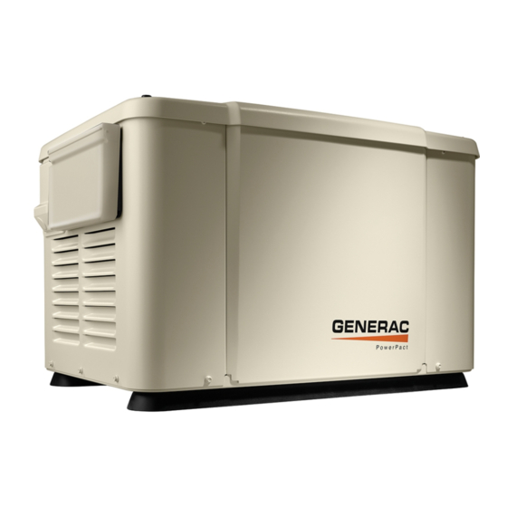
Equipment Generators: PowerPact Models - 6561, 6518, & 6519 6kW on NatGas, 7kW on LP. It has a Steel Housing, good for 18” install. We stock the PowerPact with an 8-circuit 50 Amp switch - NO whips. It is also available with a whip, and without a switch. - Page 5 Transfer Switches The Whole-House Transfer Switch amperage must be equal to or greater than the generator output or service amperage, whichever is greater. Air-cooled Generators 6 to 22kW will put out 25 to 91.6 Amps. Generac’s are smart generators with dumb switches. ...
- Page 6 RTSJ200A3 Switch This switch is basically a combination of the RTSY200A3 and the RTG16EZA1 switches. It's a 200-Amp Whole House Service Entrance Switch that load sheds to a 16-circuit priority load center. This Switch will become obsolete in 2015.
-
Page 7: Pick Up And Delivery
Optional Items You May Purchase from Better Power Starting Battery, Warning Stickers, Cold Weather Kit, Remote Monitors, Brownout Kit, PMM Kit and Modules, also SymCom Timers SMM Smart Management Modules & Smart AC Modules ... -
Page 8: Site Selection And Preparation
Site Selection and Preparation This section can be found on page 10 of the Installation Guidelines for Air-cooled Generators. Location of Generator •Air-cooled generators should be located as close as possible to the transfer switch and fuel supply. •There must be 5 feet of clearance around the gas meter. •Leave adequate room around the area for service access (check local code), •Place high enough to keep rising water from reaching the generator. - Page 9 Generac doesn't recommend a wood box platform. Why waste a perfectly good pallet? HPS found this one - Nice Pad.
- Page 10 And the internet say’s - The shed that this generator is mounted in greatly reduces the noise level. NO…..NO……NO!!!!!!! Another one found by HPS - Needs more air flow That's better...
- Page 11 Wood Deck- Not recommended Allow sufficient room on all sides of the generator for maintenance and servicing. DO NOT install under wooden decks or structures unless there is at least four (4) feet of clearance above the generator, three (3) feet of clearance on sides and front, and 18 inches of clearance at back of unit.
- Page 12 I guess Koehler's don't need air flow. DO NOT install under wooden decks or structures unless there is at least four (4) feet of clearance above the generator, three (3) feet of clearance on sides and front, and 18 inches of clearance at back of unit.
- Page 13 Install the unit • where rain gutter down spouts, roof run-off, landscape irrigation, water sprinklers or sump pump discharge does not flood the unit or spray the enclosure, including any air inlet or outlet openings. Here they used ceramic floor tiles for a border, gutter downspout, and a window.
- Page 14 The genset must be installed on a level surface. The base frame must be level within 1/2 inch all around (Nexus manual says 2”). The generator is typically placed on pea gravel or crushed stone. Pea gravel - must be 4" (102mm) deep, compacted and level. You may build a frame around the area that you want to install the generator.
- Page 15 Looks nice but pavers eventually get out of level, and the generator will walk if it’s not bolted down. Not a good idea. Wood deck and bolted down with shipping straps.
- Page 16 Very small concrete pad. Now that’s a Pad!
- Page 17 I hope this isn’t PVC ??? And NEMA-3R Switch? See the Generator Clearance handout for more details 18 inches (457mm) from the back side of the generator to a stationary wall or building. For adequate maintenance and airflow clearance, the area above the generator should be at least 4 feet with a minimum of 3 feet at the front and ends of the enclosure.
- Page 19 DO NOT Install Inside the House! Installing the Optional Fascia Kit Screw the four rubber bumpers into the threaded holes on the inside ends of the fascia. Snap one of the end pieces on to the front Fascia and the other end piece on to the rear fascia. ...
-
Page 20: Fuel Requirements & Pipe Sizing
Gaseous Fuel Requirements and Installation This section can be found in: Page 16 thru 21 in the Installation Guidelines Air-cooled Generators Page 7 thru 9 in the Generac Generator Sizing Guide Most Generators using gaseous fuels have a higher kW rating on Propane vs Natural Gas. ... - Page 21 Fuel Consumption Chart from Sizing Guide (Also see the Spec Sheet for the Generator) PowerPact Fuel Specs Special Situations to Consider Prior to installation, consult local fuel suppliers and/or the fire marshal to check codes and regulations for proper installation. Local codes will mandate the correct routing of gaseous fuel line piping around gardens, shrubs, and other landscaping.
- Page 22 Converting from NatGas to LP •The Guardian Series Air-cooled Generators are configured at the factory for NatGas. •To switch over to LP, turn the orange fuel conversion knob towards the marked fuel source arrow until it stops (clockwise). • If needed, push in and use pliers to break free in the correct direction of the arrow. •...
- Page 23 PowerPact – Use pliers to squeeze clamp and remove hose from fuel inlet Remove the NatGas Jet and insert the Propane Jet, reinstall the hose. Basic Requirements for Gas Piping All pipe sizing construction and layout must comply with NFPA 54 for NatGas and NFPA 58 for LP. ...
- Page 24 Gas Pipe Sizing Gas pipe under-sizing is one of the most commonly made mistakes. A properly sized gas pipe is critical to the proper operation of the generator. Gas line connections should be made by a certified plumber familiar with local codes. ...
- Page 25 PowerPact NatGas 5-7" WC PowerPact NatGas 3.5-5" WC Synergy 20kW NatGas Charts...
- Page 26 PowerPact Propane Synergy 20kW Propane...
- Page 27 Gas Regulator Issues The Primary Regulator for the propane supply is NOT INCLUDED with the generator. Note: LP Pipe sizes given in the manual are using a second stage regulator. When sizing a secondary regulator for LP or High Pressure NatGas, be sure to note the Maximum individual load capabilities which will be lower than the total capacity.
- Page 28 The Demand regulator on the 8kW single cylinder generator only has one side. The twin cylinder 11 - 20kW units have a two sided regulator. Plumbing the Generator The Generator must be plumbed directly from the source, NOT off the end or tee of an existing system.
- Page 29 Pipe elbows, tees, drip legs, etc. - ADD 2.5 feet (.76m) per EACH elbow, tee, etc. to the overall calculated distance from the source to the generator. (Some local codes require you to add 5 feet.) Do NOT install Street Elbows, they restrict the gas flow thru the pipe. ...
- Page 30 Don't bend the flex hose!! The flex hose is used for vibration and ground movement, NOT to go around corners or change direction of the gas line. Flex hose must be horizontal NOT vertical. Do NOT attach directly to the Generator!
- Page 31 Test for Leaks and Pressure Check the installation for leaks by spraying all connection points with a soap solution made of dishwashing soap and water. You should not see the solution being blown away of form bubbles. (A gas installer may have better leak test procedures) ...
-
Page 32: Transfer Switches
Transfer Switches GenReady Info: This section can be found in the GenReady Load Center and Transfer Switch Owner’s Manual, Page 5 and 6. RTG-EZ Switch Info: This section can be found in the Installation Guide For Pre-wired Automatic Switch/Load Center Models, pages 4 and 5. - Page 33 RTG-EZ Switches The RTG-EZ Switches are NEMA-1 and must be mounted inside next to the main Panel The 50A 10 & 12 Circuit Switches can be flush mounted The NEW RTG16EZA3 Switch is NEMA-3R and has No whips. PowerPact RTG8 - 50A 8 circuit switch GenReady Advanced ...
-
Page 34: Basics Of How The System Works
RTSR/P /C Non-Service Switch The RTSR/P/C Switches are NEMA-3R and can be used inside or outside All of RTS and GenReady switches are compatible with any Generac Air-cooled permanent standby generator (depending on sizing requirements) - except the for the RTG switches - the 7/8kW is compatible with 10, 12, and 16 circuit switches, 10/11kW is compatible with 12, and 16 circuit switches, 16/16kW is compatible with the 16 circuit switch. - Page 35 Generac Control Cable is 18AWG 7 conductor TFFN 600V 90degC dry, 75degC wet, UL Listed Type TC-ER UL1277 Probably requires 300-600V rated wire. Thermostat wire will not meet code. N1, N2, & T12 are 120V. Must meet local code. Also available two sizes of Generac Power /Control Cable. Power wires &...
- Page 36 Typical Transfer Switch diagrams – 120/240V 1ph...
- Page 39 Three possible configurations with On Grid Solar/Wind Systems. Consult with a Solar/Wind Installer for the exact configuration. The Solar/Wind Inverter MUST be installed so it does NOT see the Generator when the Generator in online.
-
Page 40: How To Wire Switches
How to wire Transfer Switches All Generac Transfer Switches have the same basic wiring. See the Manuals, Install Guides, and Handout for detailed instructions. Utility & Generator Power wiring – GenReady, RTSY/T/W,B, & RTSJ,& RTSR/P/C/I (as Service Entrance Switch) Contact the Utility to turn off the power before attempting to connect the utility side of the switch. - Page 41 (RTSR/P/C, RTSI) The RTG Switches customer load leads are prewired.
- Page 43 Control Wires Control wires between the switch and the generator consist of: Utility voltage sensing wires N1 and N2, Operating control wires #23,and 15B or 194 and 0, And don't forget T1 120VAC for the Battery charger. GenReady ...
- Page 47 Multiple RTS Switches You may run into a situation where you need to switch two panels from a single generator. You can run two RTSY/T/W/R/P/C switches together with no additional equipment. On rare occasions you may need more than two switches. ...
- Page 48 Two RTS Transfer Switch - Wiring...
- Page 49 Three to Ten RTS Transfer Switch Wiring...
-
Page 50: How To Wire The Genset
Wiring the Generator This section can be found in the Installation Guidelines for Air-cooled Generators, page 21 thru 23. •Do Not Install the Battery until the Switch and Generator installation is complete. •The Generator Control board requires 12VDC to operate when the Generator is off. •If you don’t have T1 (120V) from the switch (live) to the Generator Control board. - Page 51 RTSY/T/W, RTSR/P/C, RTSB, RTSI, RTSJ, and GenReady Switches Run the A/C main wires (E1, E2, Neutral, and Ground as well as the control wires N1, N2, T1, 23, 0, and 15B or 194) through the proper conduit to the generator. All Switches ...
- Page 52 Your wiring will come into the unit just above the gas manifold.
- Page 53 The main A/C Standby Source wires go into the Breaker panel on the side of the generator. E1 and E2, remove the two cap plugs behind the breaker door to the right of the main breaker. Insert into the bottom lugs and torque to spec. ...
- Page 54 Neutral Bonding For installations that require the neutral to be bonded to the ground, this is to be done on the customer connections terminals inside the generator. Connect a suitably sized wire from the neutral bar to the ground bar. ...
- Page 61 Common Alarm Relay On the low voltage side of the terminal block there is a common alarm relay connection. This can be used to connect to a home security system to send a signal that the generator has failed and needs service.
- Page 62 Installing the Battery The Required Battery for Generac Air-cooled generators is a Group 26R 525CCA or greater. Use of a • smaller battery may void the warranty. (PowerPact Group U1 300CCA or greater) Before installing the battery, complete the following steps: •...
- Page 63 Control Panel/Activation-Registration This section can be found in the Installation Guidelines, Air-cooled Generators, page 24 through 27. Control Panel Interface WARNING: With the Auto button pushed in, the engine may crank and start at any time without warning. Automatic starting occurs when utility power source voltage drops below a preset level or during the normal exercise cycle.
- Page 64 Control Panel LCD Display The Home page is the default page that will be displayed if no keys are pressed for five minutes. This page normally shows the “current status” message and date and time. The highest priority alarm and/or warning will also be posted on this page. ...
- Page 65 Entering the Activation Code Use the arrow keys to scroll to the desired language. Press enter to select Press enter to begin the activation process If you already have the activation code - wait 3 - 5 seconds. Use the arrow keys and scroll to the first number of your activation code.
-
Page 66: Activation
Activation is complete when all the numbers are entered and the display shows - Select Hour (0-23) Installation Wizard The maintenance intervals will be initialized when the exercise time is entered. The Factory set exercise time is Wednesday at 1:00pm. The exercise time can be changed at any time via the edit menu. -
Page 67: Initial System Tests
When the sequence is entered correctly all the LEDs will scroll from bottom to top 5 times. The Off button will light. The Generator is ready to operate. Setting the Exercise Timer - PowerPact Note: Do not attempt this until the Generator is ready to be started. ... - Page 68 Check Manual Transfer Switch Operation DANGER - DO NOT attempt manual transfer switch operation until ALL power voltage supplies to the transfer switch have been TURNED OFF! Failure to turn off all power voltage supplies to the transfer switch will result in extremely hazardous and possibly fatal electrical shock.
- Page 69 RTSY/T/W, RTSR/P/C, RTSB, & RTSI Switches RTSJ Switch Test GenReady Switches Manual operation must be checked BEFORE the transfer switch is operated electrically. To check manual operation proceed as follows: 1. Put the generator in the OFF mode. 2.
- Page 70 Do Not send power to the house before Electrical checks/tests have been performed! Voltage Checks Turn ON the Utility power supply to the transfer switch using the Mainline circuit breaker (Utility Service Disconnect Breaker). The RTG EZ switch may require the 2-pole transfer switch breaker in the main panel to be turned on also.
- Page 71 RTG, RTSR/P/C, RTSY/T/W, & RTSJ Measure across ATS terminal lugs E1 and E2. Also check E1 to Neutral and E2 to Neutral. GenReady Measure across Generator Supply Switch terminals. Also check each switch terminal to Neutral. a - Frequency - 60-62Hz ...
- Page 72 DANGER - Proceed with Caution, Generator Output Voltage is now being delivered to the transfer switch terminals. The transfer switch is now electrically HOT. Contact with live terminals results in extremely dangerous and possibly fatal electrical shock. Turn on electrical loads to the full rated wattage/amperage of the generator. ...
- Page 73 Loadshedding...
-
Page 74: Loadshedding/Smm Smart Management Modules
SMM Smart Management Modules SMM Modules are designed to prevent an overload on the generator when it is supplying the • customer loads. Up to eight loads can be managed by using SMM Modules. • The SMM Modules manage the loads by shedding the connected loads in the event of a drop in •... -
Page 81: Load Shedding Rtsy/T/W-R/P/C, Rtsb, & I
Load Shed Info and Wiring RTSY,RTSR, RTSB/RTSI There is NO Load Shedding in the RTST & RTSP Switches (there is a set of Aux. Contacts to lock out a load) RTSW & RTSC have the Smart AC Module to Loadshed up to four AC units. They install just like the OPCB Air 1 &... - Page 82 Priorities 1-2, 3-4 Priority 1 and 2 have connections for both 1 air conditioner and 1 contactor (PMM). Both an air conditioner and contactor (PMM) can be used at the same time if desired. To control an air conditioner, no additional equipment is required. Internal relays interrupt the thermostat 24VDC control signal to disable the air conditioner load.
- Page 83 Up to 4 contactors (PMMs) can be controlled by the OPCB (24VDC or 120VAC is supplied through the OPCB to energize each contactor coil).
- Page 84 Generator Overload Condition Generator overload condition is determined by generator frequency. Loads are shed when the frequency is less than 58Hz for 3 seconds or less than 50Hz for 1/2 second (for 60Hz). The OPCB has a test button that forces the unit to act as if an overload has occurred. ...
- Page 85 Air 1 and Air 2 OPCB terminals (A/C1, A/C2, A/C3, A/C4 on the Smart AC Module) Route the thermostat cable (from the furnace to the outside air conditioner unit) to the transfer switch. Route the cable away from High voltage wires. ...
- Page 86 Testing the Overload Prevention Control Board (OPCB) A test push button is provided on the bottom of the OPCB to test the operation of the tested functions. The test button will work when the ATS is in the Utility or Generator position. ...
- Page 87 Synergy Loadshedding The 20kW Synergy must use the RTSB200A3 or RTSI200A3 switch with fast Loadshed. The Synergy Loadshed installs and works exactly like the RTSY/RTSR switch, except when there are any loads greater than 10kW / 2hp motors on LP or 9kW on NatGas ...
-
Page 88: Prolonged Outages
RTSJ Switch Only Test Load Shed Function - Press the Load Shed Reset/Test pushbutton for more than 6 seconds on the outside of the ATS door. Release the pushbutton when the Load shed switch actuates disconnecting the non-essential loads. ... -
Page 89: Cold Weather Kit
6212 Cold Weather Kit Do Not install until unit has completely cooled. Set the generator to OFF. Remove 7.5A fuse and disconnect at the transfer switch any utility inputs to the unit. Remove front panel, remove fasteners securing control panel cover and remover cover. ... -
Page 90: Mobilelink
6463 Mobile Link Verify that there is Cell Phone Texting service available at the generator site. (usually Verizon and AT&T) Do NOT throw out the Box or any packing materials at this time. (You will need some numbers from the box when you activate the unit) ... - Page 91 Evolution controllers the accessory port is located underneath the controller covered with a decal labeled Accessory Port 1. Remove the decal and plug in the harness. The plug will only fit one way. Do Not force. The power wires of the harness go directly to the battery.
-
Page 92: Local Remote Monitor (Basic)
Mobile Link Enrollment/Activation You will need the following information to activate the unit: One to Four E-mail addresses One to Four Cell phone numbers (with texting capabilities) Model Directory Number (MDN) located on the bottom of the Mobile Link of the box it came in. ... - Page 93 Display unit installation Install two AAA non-rechargeable alkaline batteries in the display unit. (The expected life of the batteries is six months.) There is no power switch; the monitor will power up when the batteries are inserted. Low Battery Indicator ...
-
Page 94: Utility Voltage Monitor Timer (Brown Out)
The generator will not start or will be shut down if already running. The Red light will flash every 5 seconds. The internal buzzer will sound once every 5 seconds. The buzzer may be silenced by briefly pressing and releasing the test button (after the buzzer has sounded). -
Page 96: Warning Stickers
Bundle the newly added wires along the existing harness and tie to the harness as needed. Plug the timer relay into the socket. Set up the controls as follows: Post-Installation Test Close the circuit breaker on the generator, and place the generator in the AUTO mode. ... -
Page 97: Bad Installs
Some more Bad Installs... - Page 98 Service Entrance cable to the Generator...
- Page 100 We hope this information will help make your installs safe, easy, and your customers Happy. Also Available from Generac & Better Power QT/RG Series - Liquid-cooled GenSets 22kW - 150kW Single & Three Phase RD Protector Series - Diesel GenSets 15kW - 50kW Single & Three Phase Generac iX, iQ, GP, LP, XG, &...
Need help?
Do you have a question about the PowerPact 6561 and is the answer not in the manual?
Questions and answers