
Related Manuals for MKS 946 Series


Summary of Contents for MKS 946 Series
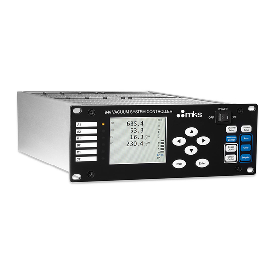
- Page 1 Series 946 Vacuum System Controller Operation and Maintenance Manual Instruction Manual p/n: 100018121 Rev A, June 2020...
-
Page 2: Table Of Contents
Serial Communication Response Format ................... 16 Feature, Control Locations and Dimensions ..........17 Typical Applications for the Series 946 Controller ........19 MKS Series 946 Vacuum System Controller ..........20 Operating the Series 946 Controller ............22 Power ........................ 22 Front Panel Control Lock ................... - Page 3 Installing a Pressure Control Valve ..............74 7.7.1 Installing an Upstream Solenoid Valve ..................74 7.7.2 Installing a Downstream MKS 153 or T3B Throttle Valve ............75 Connecting Relay and Analog Outputs ............. 77 8.1 Connecting 946 Relay Outputs ..................77 8.1.1 Pin Out for the 946 Relay Output ....................
- Page 4 Pressure Control (PC) Module ................. 108 10.4 Mounting the 946 Controller ................109 10.5 AC Power Cord ....................110 Maintenance and Service of MKS Vacuum Sensors ......111 11.1 422 and 431 Cold Cathode Sensor ..............111 11.1.1 Cold Cathode Theory ....................... 111 11.1.2...
- Page 5 Visit our website at: www.mksinst.com Warranty Information MKS Instruments, Inc. provides an eighteen (18) month warranty from the date of shipment for new MKS products. The MKS Instruments, Inc. general terms and conditions of sale provide the complete and exclusive warranty for MKS products. This document is located on our web site at www.mksinst.com, or may be obtained by a contacting an MKS customer service representative.
-
Page 6: Safety Information
Failure to comply with these precautions or with specific warnings elsewhere in this manual violates safety standards for the intended use of the instrument and may impair the protection provided by the equipment. MKS Instruments, Inc. assumes no liability for the customer’s failure to comply with these requirements. - Page 7 Do not substitute parts or modify the instrument. Do not install substitute parts or perform any unauthorized modification to the instrument. Return the instrument to an MKS Calibration and Service Center for service and repair to ensure that all safety features are maintained.
-
Page 8: Specifications
2 Specifications 2.1 Controller Pressure measuring range 1 x 10 to 1.0 x 10 Torr 1 x 10 to 1.3 x 10 mbar 1 x 10 to 1.3 x 10 Relay set point range CC (Cold Cathode) 2.0 x 10 to 5.0 x 10 Torr 2.7 x 10... - Page 9 Storage temperature range -10° to 55°C (14° to 131°F) Relative humidity 80% maximum for temperatures less than 31°C, decreasing linearly to 50% maximum at 40°C Altitude 2000 m (6561 ft) maximum Insulation coordination Installation (Over-voltage) Category II, Pollution Degree 2 Power requirement (nominal) 100 - 240 VAC, 50/60 Hz Mains voltage...
-
Page 10: Pressure, Flow Sensors, & Valves
FC (Mass Flow Controller) MKS G, I, P Series and legacy products with tied internal grounds, MFCs requiring ±15 VDC or +15 to +24 VDC, 0 - 5 VDC set point and standard 15 pin or 9 pin D-sub cable... - Page 11 Air/nitrogen, Argon, Helium Any (gas independent) Nitrogen A fast response (<3 msec) Cold Cathode board is also available. Consult MKS for details. Trailing zeros displayed on LCD screen do not reflect the resolution of the pressure reading. 946 Controller Instruction Manual...
- Page 12 Installation orientation CC, HC, CM, Pirani, FC Any (port down suggested for pressure sensor) Body horizontal only Materials exposed to vacuum may include Series 431 and 422 – SS 304, Al 6061, silver-copper brazing alloy, alumina ceramic, Elgiloy , OFHC copper ®...
- Page 13 10° to 50°C (50° to 122°F) CM & FC 0° to 50°C (32° to 122°F) Maximum Sensor bakeout temperature (without cables) Series 431 – 250°C (482°F) when backshell subassembly removed, 125°C (257°F) otherwise Series 423 – 400°C (752°F) CF flange version only with magnet removed Series 422-versions bakable and operable to 250°C are available.
-
Page 14: Controller Display
Mini BA 1.12X2.37 in (2860 mm) with 2-3/4” CF flange 3.3X1.0 in (83 mm25) with 2-3/4 CF flange, can insert into NW40 tube. Pirani 1.3X4.4 in (34112 mm) 1.6X4.4 in (41112 mm) Types 622A, 623A and 626A - 2.64.8 in. (66121 mm) Type 722A- 1.53.9 in (3899 mm) FC (HWL) 1179A -<5.5<1.53 in (<14.0<3.87.6 mm) -
Page 15: Display Resolutions
RP OFF The sensor power is turned OFF remotely REDETECT Detecting the sensor type for PR/CP _ _ _ _ No Pirani/CP/HC/MFC sensor is detected on the inserted Pirani/CP board NOBOARD No board is detected in the slot, display only last 5 secs N2, AR, He Gas type User calibration... -
Page 16: Serial Communication Response Format
Pressure Range Convection Pirani Pirani Hot Cathode Cold Cathode Default Default Torr PatchZ HighR PatchZ HighR PatchZ Default HighR PatchZ Default HighR X.X0E+03 X.XE+03 X.00E+02 X.X0E+02 X.XE+02 (X=1,2,3,4) X.XE+02 X.X0E+01 X.XE+01 X.X0E+01 X.XE+01 X.X0E+00 X.XE+00 X.X0E+00 X.XE+00 X.X0E-01 X.XE-01 X.X0E-01 X.XE-01 X.X0E-02 X.XE-02... -
Page 17: Feature, Control Locations And Dimensions
Feature, Control Locations and Dimensions Power 946 VACUUM SYSTEM CONTROLLER 1.00E-10 Torr Ctrl Channel System Setup Setup 1.00E-10 Ctrl Pressure Open Control Degas 1.20E-03 Close On/off SP10 3.50E-02 Sensor SP11 Setpoint On/Off SP12 Enter Remote 8.87(225) 9.47(241) Figure 3-1 946 Front Panel Figure 3-2 946 Rear Panel Example 946 Controller Instruction Manual pg. - Page 18 Channel Label LED, Indicating Active Channel Liquid Crystal Display Push Buttons for Menu Navigation Power Switch AIO Module AC Power Inlet RS232/485 Communication Port Relay Output Port Analog Output Port Pressure Control Module Capacitance Manometer Module Mass Flow Control Module Pirani Module Figure 3-3 946 External Dimensions (inches) 946 Controller Instruction Manual...
-
Page 19: Typical Applications For The Series 946 Controller
Typical Applications for the Series 946 Controller • Wide pressure measurement range in vacuum chambers. • Integrated vacuum process control with simultaneous flow, pressure, and valve control. • Pressure control in vacuum systems and process sequencing using relay set points. •... -
Page 20: Mks Series 946 Vacuum System Controller
MKS Series 275 Convectron sensors (up to 6) • MKS Mass Flow controllers (up to 6), Types G, I, P Series with tied grounds and legacy products, requiring +/- 15 to + 24VDC, 0-5 VDC set point and standard 15 pin or 9 pin D-sub cable connection MKS 179A, M100MB Mass Flow Meters (up to 6) •... - Page 21 • Pressure readings for all sensors connected to the controller (up to 6) • Operational status of MFCs and pressure control valve via the front panel • The type of pressure and flow sensor in operation • Mass flow rates for all MFCs connected to the controller (up to 6) •...
-
Page 22: Operating The Series 946 Controller
Operating the Series 946 Controller 6.1 Power 946 Vacuum System Controller can be powered by universal AC voltage (100 to 240 V, 50/60 Hz). The power can be switched ON and OFF using the Power switch on the front panel. It is recommended to power OFF the controller when not in use. - Page 23 10.03 Torr 100.7 SCCM 8.9% 2001 SCCM 50.15 SCCM 2.1% 10.05 1.0E+1 SP10 9.982 SP11 SP12 125% REMOTE Figure 6-1 946 LCD Front Panel Display for Pressure Measurement with either Valve Pressure Control Mode (upper) and MFC Ratio Control Mode (lower). Type of sensor detected (CC = Cold Cathode, HC = Hot Cathode, PR = Pirani, CP = Convection Pirani or Convectron, CM = Capacitance Manometer or 902B Piezo, FC = Mass Flow Controller);...
-
Page 24: Large Font Display
6.3.2 Large Font Display A special large font pressure display of a single channel is also available to ensure the pressure readings can be seen at a distance. To enter this mode: 1. While in the standard display mode, press either the or the key to select the desired channel, as indicated by the green LED. -
Page 25: Display System Setup Parameters
Panel Default Parameter Function Button value range Torr mBar RS232 Pascal RS485 Micron 1 to 253 9600 19200 38400 P UNIT Torr Com Type RS232 57600 115200 Address Baud Rate 9600 Cmd Mode Parity NONE None Even Set Param Enable User cal Enable SYSTEM... -
Page 26: Change And Save A Parameter Value
6.4.3 Change and Save a Parameter Value To change and save a system setup parameter value, use the following procedure: 1. Press any of the keys to move the cursor to the parameter to be changed. Enter Torr 2. Press the key to highlight this parameter value. - Page 27 946. See section 6.7 for more detailed ratio recipe setup. 11. Valve type Several types of MKS valves can be operated by the 946 to control the system pressure. Valve type allows selection of the valve type.
- Page 28 13. Combination Setup Two analog output combination channels are available on the 946. Up to 3 vacuum pressure sensors can be assigned to each combination channel. Refer to section 8.4 for a more detailed discussion of the settings for the combination channels. 14.
- Page 29 When selecting A from the front panel, only multiples of 1, 2, and 5 are allowed. Following are some examples for A corresponding to P max. 1×10 2×10 5×10 1×10 1×10 2×10 5×10 1×10 1.5×10 1E+4 5E+3 2E+3 1E+3 1E-1 5E-2 2E-2 1E-2...
-
Page 30: Channel Setup For Pressure Measurement
6.5 Channel Setup for Pressure Measurement 6.5.1 Overview of 946 Channel Setup Front panel setting of the parameters associated with devices connected to the 946 Controller such as calibration, gas selection, relay set point, control set point, and control channel selection are accomplished using Channel Setup. - Page 31 Gas Type Factory Default Manual Zero Auto Zero Pirani ATM Value Ion gauge Channel and CP ATM Cal Display 2 Relays, Ch# auto detected Relay Relay n Enable ABOVE BELOW BELOW SET SP 1.0E+00 2x10 to 9.5x10 torr for PR Hyst 1.5E+00 2x10...
-
Page 32: Setup For A Capacitance Manometer
Range 1000 0.02 to 20,000 Factory Default Manual Zero Auto Zero Ion gauge Channel Operation Voltage +/- 15V Relay Relay n Display 2 Relays, Ch# auto detected Enable BELOW ABOVE SET SP 1.00E+01 BELOW Hyst 1.50E+01 1% to 95% of its full scale Message Display warning message Channel... - Page 33 3. Range The full-scale pressure range of the capacitance manometer in use needs to be set. Capacitance manometers with full scale (ranges) from 1x10 to 1x10 Torr can be operated. Only 3 selections are available in each decade (1, 2, and 5), except between 1,000 to 10,000 Torr where 1500 Torr is allowed.
- Page 34 Full scale of CM 1000 Torr 100 Torr 20 Torr Table 6-1 Vali d Gaug es f or Autozeroing Capacit ance Mano met ers The Capacitance Manometer and the reference auto-zero sensor must be connected to the same chamber at all times. 6.
-
Page 35: Setup For A Cp (Convection Pirani), Convectron, Or Pr Sensor
11. SET SP displays the entered and saved setpoint trip value. To change the value, scroll to the value to be changed, highlight by pressing Enter, and then adjust to the desired value with the keys. Confirm the change by pressing Enter. The range is 1% to 95% of the manometer’s full scale. - Page 36 Auto-detected Setup Convection Pirani Gauge C2 Sensor Gas Type Auto Zero Manual Zero ATM Value 7.6E+02 ATM Cal Message Relay Enable SET SP Hyst Relay 11 ENABLE ABOVE 1.0E-02 9.0E-03 Relay 12 CLEAR BELOW 3.0E-01 3.3E-01 Auto-detected Figure 6-9 Pirani/Convention Pirani Setup Information Screen 1.
- Page 37 Ensure that the Convection Pirani/PR and the reference auto-zero CC/HC sensor are connected to the same chamber at all times. 5. Manual Zero The Convection Pirani or Pirani sensor can be manually zeroed. To do this, select YES in the box next to Manual Zero and then push ENTER.
-
Page 38: Setup A Cold Cathode Sensor
sensors. The speed of the value change can be increased by continuously pressing the key. 12. Hyst When a set point value is changed, the hysteresis value will be changed automatically. If DIR is set to ABOVE, the hysteresis will automatically be set to 0.5xSet point; if DIR is set to BELOW, the hysteresis is automatically set to 1.5xSet point. - Page 39 Setup CC Gauge A1 U Cal 1.0E+00 AO Delay Fast Relay SP 1.0E-05 Prot SP 5.0E-03 Relay Enable Dir/Ch SET SP Hyst Relay 01 BELOW 1.0E-06 9.0E-07 Relay 02 CLEAR BELOW 3.0E-05 3.3E-05 Relay 03 ENABLE BELOW 2.0E-08 1.8E-09 Relay 04 CLEAR BELOW 5.0E-07...
- Page 40 Once the Protect Set Point is triggered and the sensor turned OFF, the auto control via the Control SP is disabled. The gauge can only be turned back on manually or by serial command. When control mode is used, the Control SP should be set to a pressure lower than the Protect Setpoint to ensure the cold cathode is controlled by the higher pressure sensor.
-
Page 41: Setup A Hot Cathode Sensor
full scale). This prevents the cold cathode from operating at high pressure, extending the service life. The adjustable Control SP range depends upon the sensor used for control. 2x10 to 1x10 Torr for a Convection Pirani or Convectron sensor 5x10 to 1x10 Torr for a Pirani 0.2% of full scale to 2x10... - Page 42 2. Filament Indicates the filament in use. The choices are 1 or 2. Setup HC Gauge A1 Gas Type Filament DG Time Sensitivity 20 uA Protect Setpoint 5.0E-03 Relay Enable Dir/Ch SET SP Hyst Relay 01 BELOW 1.0E-06 9.0E-07 Relay 02 CLEAR BELOW 3.0E-05...
- Page 43 11.3.1. Nominal Sensitivity values are 9 Torr for the MKS Low Power Nude sensor, and 12 Torr the Mini BA sensor. These values will be automatically selected based on the type of sensor detected on power up, if no user-defined sensitivity value has been stored. Sensitivity values from 1 to 50 Torr can be entered from the front panel or over communications.
- Page 44 Refer to Figure 8-1 and Section 8.1.2 for a more detailed description of the direction setting. 10. SET SP SET SP displays the entered and saved setpoint trip value. To change the value, scroll to the value to be changed, highlight by pressing Enter, and then adjust to the desired value with the keys.
-
Page 45: Power Control Of A Pressure Sensor
• SAFE: The filament for a Hot Cathode sensor will be automatically turned OFF by the controlling sensor, but the HC can be turned ON manually. • OFF: The Hot Cathode must be turned ON/OFF manually. Even if a control channel is selected, the HC will not be turned ON or OFF. -
Page 46: Power (Including Degas) Control Of A Sensor Via 37 Pin Aio D-Sub Connector
Up to 3 MKS low power nude or Mini BA sensors can be degassed simultaneously. The pressure must be below 1x10 Torr in order for the degas cycle to begin. If degas is attempted at a higher pressure, the Controller will display HIGH PRES for 10 seconds and will not start a degas. -
Page 47: Channel Setup For Flow Measurement And Mfc Based Pressure Control
Control When an MFC module is installed, the 946 Controller can operate MKS Mass Flow Controllers to control the mass flow rate or operate a mass flow meter to monitor the mass flow rate. Up to six MFCs can be simultaneously operated by one 946. -
Page 48: Setup Mfc Controlling Parameters For Flow Control
The flow set point should be set via the MFC Channel Setup screen as described in section 6.7.2. Due to the limited space, only 3 digit resolution is displayed (for example, a set point of 1350 sccm will be displayed as 1.35E+3). 6.7.2 Setup MFC Controlling Parameters for Flow Control When an MFC is connected to the 946 controller, parameters must be entered and set in order to ensure the proper operation. - Page 49 1.0 to 1.00E+6 SCCM. When MFCs with a flow rate specified in SLM are used, the SLM value needs to be multiplied by a factor of 1000 to convert SLM to SCCM. 3. Zero Before zeroing the MFC, ensure the gas flow through the MFC is zero. This can be done by equalizing the pressure across the MFC.
-
Page 50: Set Mfc(S) For Dynamically Controlling System Pressure
7. Flow Rate SP Flow Rate SP is the entered flow rate set point for MFC set point mode operation. The MFC can be set to close when the set point value is less than 2% of the full scale and to open when the set point value is greater than the full scale (100%). - Page 51 Pressure Control Parameter Setting Recipe PID Ch P Ctrl Ch P Sp 5.0E+2 Prop - Kp CtrlStart 1.0E+1 Integral - Ti Start 1.0E+1 0.0% Derivative - Td 1.5E+0 30.0% Base Ceiling 0.0% 90.0% Direction Preset Upstream GainSchedBand SchedGainCoeff Figure 6-14 Single MFC Control Recipe Setup Screen The Base, Ceiling, Preset, Start and End are the percentage of the full-scale flow rate of the MFC on the assigned PID channel, not the actual flow rate.
- Page 52 c) When a valve is used for pressure control, select Vlv and confirm with Enter. d) NA indicates no method of controlling pressure has been selected. • P Ctrl Ch: This assigns the sensor channel for pressure control and available options are automatically detected.
- Page 53 signal amplifies noise, and may cause instability in the process control if the noise and the derivative gain are sufficiently large. • Ceiling: Ceiling is a control parameter that sets the upper limit of the control signal output. This is expressed as a percent of full scale for a MFC or the percentage of the valve opening for a valve.
- Page 54 b) If Ceiling setting is less than the Start value, the Start will be overridden by Ceiling. The range is from 0 to 100% of full scale for a MFC, or from 0 to 100 % for a control valve. The default setting is 0, and it must be equal or larger than Base parameter value.
- Page 55 Scheduled PID control zone Normal PID control zone Time Figure 6-16 Schematic of a Scheduled PID Control 6.7.3.1.2 Activate PID Pressure Control using Single MFC Once a PID control recipe is properly defined, a PID control can be activated for controlling the system pressure.
- Page 56 399.3 Torr 4.0E+2 10.07 10.01 SCCM 250.0 SCCM 300.5 SCCM 1.300 SCCM Close Figure 6-18 Front Panel Display during PID Control using Single MFC • During PID control process, the active MFC flow reading and corresponding controlling pressure gauge reading are displayed in blue color to identify these channels.
- Page 57 accumulated integral errors will not be reset to zero for the PID control. If resetting of integral error is desired, the PID control must be restarted. 6.7.3.2 Set Ratio Control of System Pressure using Multiple MFCs In some processes, it is necessary to maintain the system pressure with multiple process gases while keeping the gas compositions unchanged.
- Page 58 MFC Ratio Recipe Channel Ref flow Range 1.00E+2 20.0 5.00E+2 0.00E+0 2.00E+2 0.00E+0 1.00E+3 4.00E+2 80.0 1.00E+3 Figure 6-20 Ratio Recipe Setup Screen for Multiple MFC Pressure Control Four (4) ratio recipes (RR1 to RR4) can be defined. While editing a recipe, the ratio recipe is highlighted by the gray background such as the RR2 shown in Figure 6-20.
- Page 59 setpoint is limited to be less than 50% of the full scale. This enables a scaling of 0 to 200% in flow rate for all MFCs during ratio control of system pressure. Because of the range limitation (50% of the full scale) of the reference flow set point and scaling limit (200%) for flow control, the maximum gas flow will never surpass the full scale of the MFC during the dynamic ratio pressure control.
-
Page 60: Pressure Control Using A Control Valve
the active ratio channels and pressures associated with the control will be displayed in blue for identification, as shown in Figure 6-22, when the flow rates are within ±20% of the set point value. If the gas flow rate is >2% of full scale and 20% off the target setting, the flow rate readings will be in red as an alarm. -
Page 61: Valve Type Selection
Following is list of valves that can be operated by the 946 controller: • Valves (MKS 153/T3B): This valve is installed on the vacuum pumping line of a process chamber (also called downstream control valve). With these valves, larger valve openings produce lower chamber pressures. -
Page 62: Valve Control Recipe Setup
System Setup P Unit Torr CommType RS 232 Address Baud Rate 9600 Com Mode Parity None Set Param Enable User Cal Enable PID Recipe Edit Ratio Recipe Edit Valve Type Combination Setup Edit DAC Parameter Setup Edit System FV Infor Display Figure 6-24 Selection of Valve Type using System Setup Screen 6.8.2 Valve Control Recipe Setup... -
Page 63: Activate A Pressure Control With A Valve
2. Press keys to select a desired recipe (R1 to R8) for editing or displaying (highlighted by grey background), then, press to enter the edit mode. Note that the Enter cursor automatically highlights the box beside the PID Ch. 3. Move the cursor to the PID Ch, and set its parameter to Vlv. 4. -
Page 64: Terminate A Pid Pressure Control Using A Valve
The activation of a PID dynamic valve control is identical to activating a PID control using single MFC as described in Section §6.7.3.1.2. The only exception is that Vlv needs to be selected for the PID Ch. See Figure 6-27. Once a proper recipe is selected, PID pressure control is activated by changing the PID Control parameter from OFF to ON. - Page 65 2. Open the Valve: Pressure To Open the valve, press the key until the display is as shown in Figure 6-26, Control move the cursor to the box below OP Mode, and change the parameter to Open, or press button. In either case, press the key afterward to confirm.
-
Page 66: Installing Vacuum Sensors
7 Installing Vacuum Sensors 7.1 Installing Cold Cathode Sensors Veri fy that the vacu um po rt to which the CC senso r is moun ted is electr ically grou nd ed. It is essent ial for person nel safety as well as prope r op eration that the envelop e of the sens or be co nn ected to a facility grou nd . -
Page 67: Connecting The 423 I-Mag Sensor
7.1.5 Connecting the 423 I-Mag Sensor Mount the sensor to a grounded vacuum system. KF 25 or KF 40 flanged sensors must be attached with a conductive, all-metal clamp to ensure the sensor body is grounded. If the I-Mag Sensor has a CF flange, remove the magnet first to allow clearance for bolt installation. To remove the magnet, undo the two Phillips head screws in the center of the magnet housing. -
Page 68: Orienting A Hot Cathode Sensor
This hazard is not unique to this product. MKS sensors are available with either a CF type metal sealed flange, a KF type flange, or tubulation. Mount the sensor to a grounded vacuum system. KF 25 or KF 40 flanged sensors must be attached with a conductive, all-metal clamp to ensure the sensor body is grounded. -
Page 69: Installing Convection Pirani, Convectron, Or Pirani Sensors
Pins 5, 6, and 7 are used for sensor identification. The cable needs to be matched to the type of hot cathode so proper operating parameters like maximum degas power will be selected. Table 7-1 shows the cable pinouts for Low Power Nude and Mini BA sensors. Since high power is required to operate a Hot Cathode, especially, during degas, the maximum allowed cable length is 50 ft (15 m), significantly shorter than for a cold cathode sensor. -
Page 70: Locating The Sensor
The use of a screen or porous filter at the port can be helpful, such as MKS seal and centering ring assembly with screen. 7.3.4 Orienting the Series 317Convection Pirani or Convectron Sensor When measuring pressures greater than 1 Torr, the Series 317 or Convectron sensors must be mounted with their axis horizontal. -
Page 71: Preparing The 317 Sensor For Bakeout
Use an MKS adaptive centering ring (MKS p/n 100315821) to fit a KF 16 port to a KF 10 port. In applications where the system may be subject to large voltage fluctuations, a metal centering ring with a screen should be installed. -
Page 72: Installing Capacitance Manometers - Mks Baratron
The Series 946 Controller supports a number of Capacitance Manometers, including the MKS unheated Baratrons and MKS 45 C heated Baratrons. They are available in full scale ranges from 0.02 to 10,000 Torr, each with a 3-decade range. A CM module operates up to two Capacitance Manometers, and the total combined current requirement of operating sensor(s) must be 1 amp or less. -
Page 73: Series 902B Piezo
5. Leave the power to the instrument on at all times, for optimal performance. 7.6.2 Interface Cables Connect the MFC and 946 Controller using MKS cables. Cables are listed in the Spare Parts and Accessories section. Cables are available with either standard 9 or15 pin D-Sub at one end for connecting to the MFC, and high density 15 pin D-sub at other end for connecting to the 946 MFC module. -
Page 74: Setup
7.7.1.3 Connecting the Valve to 946 Controller Cable part number 100018192 can be used to connect an MKS 148/248/154 upstream valve to the 946 Vacuum System Controller. -
Page 75: Installing A Downstream Mks 153 Or T3B Throttle Valve
If the inlet gas flow rate and system pumping speed are fixed, the system pressure can be effectively controlled by adjusting the flow conductance using a downstream throttle valve such as MKS 153 or T3B control valve. Because the valve is positioned between the vacuum system and the vacuum pump, larger opening of the valve leads to higher conductance and lower system pressure. - Page 76 7.7.2.4 Setting of 153/T3B Valve and 946 Controller The 153 or T3B valve and 946 Controller need to be set as follows: • 153/T3B valve control mode must be switched to Position Control mode. For the T3B, connect pin 5 to pin 24 on the Aux I/O connector. Additionally, ensure that the interlock signal is satisfied by connecting pins 22 and 24 on the Aux I/O connector.
-
Page 77: Connecting Relay And Analog Outputs
8 Connecting Relay and Analog Outputs Relay and analog outputs require 2.5 sec time delay to stabilize after power application. 8.1 Connecting 946 Relay Outputs There are twelve relays available in the 946 Controller which can be used to control the operation of devices associated with a vacuum system. -
Page 78: Proper Setting Of A Relay
8.1.2 Proper Setting of a Relay Several parameters need to be correctly set to properly use the relays in a 946 Controller. Figure 8-1 shows that manner in which these parameters are defined. ABOVE BELOW Setpoint Hysteresis Hysteresis Setpoint Relay Relay Relay Relay... -
Page 79: Relay Inductive Loads And Arc Suppression
the sequence repeating. Such an operation is detrimental to system control and should be avoided. Thus, when direction is set to ABOVE, the hysteresis must be lower than the set point, while when the direction is set to BELOW, the hysteresis must be higher than the set point. When Direction is changed, hysteresis is set to a default value (of about 10%). -
Page 80: Buffered Analog Output
Description Description Buffered Aout A1 Log/Lin Aout C1 Buffered Aout A2 Log/Lin Aout C2 Buffered Aout B1 Combination Aout 1 Buffered Aout B2 Combination Aout 2 Buffered Aout C1 Power A1 Buffered Aout C2 Power A2/Degas A1 Log/Lin Aout A1 Power B1 Log/Lin Aout A2 Power B2/Degas B1... - Page 81 Figure 8-3 Buffered Analog Output for Cold Cathode Sensors (431/422/423) in N 946 Controller Instruction Manual pg. 81...
- Page 82 Pressure, Torr Buffered Vout, V Pressure, Torr Buffered Vout, V 1.0E-11 0.0000 4.0E-07 6.8993 1.5E-11 0.3286 6.0E-07 7.0871 2.0E-11 0.5634 8.0E-07 7.2222 3.0E-11 0.8994 1.0E-06 7.3247 4.0E-11 1.1416 1.5E-06 7.5140 6.0E-11 1.4585 2.0E-06 7.6551 8.0E-11 1.7035 3.0E-06 7.8469 1.0E-10 1.8882 4.0E-06 7.9769 1.5E-10...
- Page 83 Figure 8-4 Buffered Analog Output for Hot Cathode Sensors 946 Controller Instruction Manual pg. 83...
- Page 84 Figure 8-5 Buffered Analog Output for a 345 Pirani Sensor 946 Controller Instruction Manual pg. 84...
- Page 85 Pressure, Torr Buffered N Vout, V Buffered Ar Vout, V Buffered He Vout, V 1.0E-04 0.6323 0.6324 0.6340 1.5E-04 0.6347 0.6339 0.6362 2.0E-04 0.6372 0.6355 0.6384 3.0E-04 0.6420 0.6385 0.6426 4.0E-04 0.6468 0.6414 0.6469 6.0E-04 0.6563 0.6474 0.6553 8.0E-04 0.6656 0.6533 0.6636 1.0E-03...
- Page 86 Range Equation Nitrogen 0.63<V<9.3 V <p <20 Torr 3935 9.3 V< V <9.72 V 8696 ...
- Page 87 Figure 8-6 Buffered Analog Output for the 317 Convection Pirani Sensor or 275 Convectron Sensor 946 Controller Instruction Manual pg. 87...
- Page 88 Pressure, Torr Buffered N Vout, V Buffered Ar Vout, V Buffered He Vout, V 1.0E-04 0.5639 0.5674 0.5654 1.5E-04 0.5650 0.5680 0.5663 2.0E-04 0.5660 0.5687 0.5671 3.0E-04 0.5681 0.5699 0.5688 4.0E-04 0.5702 0.5712 0.5705 6.0E-04 0.5744 0.5737 0.5738 8.0E-04 0.5785 0.5762 0.5771 1.0E-03...
- Page 89 Range Equation Nitrogen 0.56<V<8.3 V <p <40 Torr 3156 8.3 V< V <8.8 V ...
- Page 90 Buffered Capacitance Manometer Analog Output Full Scale Range (Torr) 1000 10,000 0.01 Pressure, Torr Figure 8-7 Buffered Analog Output for Capacitance Manometers 946 Controller Instruction Manual pg. 90...
-
Page 91: Logarithmic/Linear And Combination Analog Output
8.4 Logarithmic/Linear and Combination Analog Output Since most of the buffered analog outputs are non-linear, logarithmically linearized or linear analog outputs are also provided for each individual sensor. However, since the logarithmic/linear analog outputs are processed by the microprocessor, these are updated only every 50 msec, regardless of the number of sensors being connected to the controller. - Page 92 Set Combination Channel Parameter High Middle Enable Combo #1 Enable Combo #2 Disable Figure 8-8 Setup Screen for Setting Combination Channel Parameters Once the combination sensors are selected, enable the combined analog output. If invalid channels are selected, the Enable indicator will stay in the Disabled mode. The following rules may be used to simplify the combination configuration.
-
Page 93: Logarithmic/Linear Analog Output When The Sensor Power Is Turned Off
• Query the gauge combination @254SPC1?;FF and @254SPC2?;FF . • Enable/disable the combined analog output @254EPC1!Enable;FF and @254EPC1!Disable;FF . 8.4.3 Logarithmic/Linear Analog Output when the Sensor Power is Turned OFF The following table shows the expected logarithmic/linear analog output when the sensor power is turned OFF or the combined analog output is disabled. -
Page 94: Rs232/485 Serial Communication Commands
9 RS232/485 Serial Communication Commands 9.1 Serial Communication Wiring Diagram Description RS485(-)/RS232TxD/(B) RS485(+)/RS232RxD/(A) Ground Table 9-1 946 Serial Communication Wiring Diagram 9.2 Communication Protocols Cable length with RS232 signals 50 ft (15 m) Cable length with RS485 signals 4000 ft (1200 m) Baud rate 9600, 19200, 38400, 57600, 115200 Character format... -
Page 95: Pressure Reading Commands
9.3 Pressure Reading Commands Command Function Response Meaning Single Channels Read pressure Pressure in selected units for PR, CP, CC & HC d.d0Eee (n=1 to 6) on Channel n (d,e=0 to 9) Pressure in selected units for CM d.dddEe (d,e =0 to 9) CM, when CM output is negative. -
Page 96: Relay And Control Setting Commands
9.4 Relay and Control Setting Commands Command Parameter Response Function Query or set a set point for relay m, response with the d.dd Eee d.dd Eee (m=1 to 12) current setting value. (d,e=0 to 9) (d,e=0 to 9) If 0 is used as the parameter, the set point will be set as its low limit value. -
Page 97: Capacitance Manometer Control Commands
9.5 Capacitance Manometer Control Commands Command Parameter Response Function RNGn Query or set the full-scale pressure measurement range d.dd Eee d.dd Eee (n=1 to 6) for a capacitance manometer. Valid range is from 0.01 to 10000, and default range is 1000 Torr. CMTn ABS or ABS or... -
Page 98: Cold Cathode Control Commands
9.7 Cold Cathode Control Commands Command Parameter Response Function PROn Query or set protection set point value for sensor on channel d.dd Eee d.dd Eee (n=1, 3, 5) n. The valid PRO range is 1x10 to 1x10 Torr. Use 0.0 to (d,e=0 to 9) (d,e=0 to 9) disable the protect set point control. -
Page 99: Hot Cathode Control Commands
9.8 Hot Cathode Control Commands Command Parameter Response Function PROn Query or set protection set point value for sensor on channel d.dd Eee d.dd Eee (n=1, 3, 5) n. The valid PRO range is 1x10 to 1x10 Torr. Use 0.0 to (d,e=0 to 9) (d,e=0 to 9) disable the protect set point control. -
Page 100: Mfc Control Commands
9.9 MFC Control Commands Command Parameter Response Function Read flow on Query flow reading in SCCM for MFC on Channel n. d.dd0Eee (n=1 to 6) Channel n (d,e=0 to 9) QSFn d.dd d.dd Query or set a scale factor for a MFC on Channel n. Valid (n=1 to 6) (d =0 to 9 (d =0 to 9... -
Page 101: Pid Recipe Setting Commands
9.11 PID Recipe Setting Commands Command Parameter Response Function RCPn Set or query the active recipe number. (n=1 to 8) (n=1 to 8) RDCH?n A1, B1, A2, n:CH Set or query the MFC channel for PID pressure control RDCH!n: B2, C1, C2, (n=1 to 8, associated with recipe n. -
Page 102: Ratio Recipe Setting Commands
Example 1: To query the proportional gain Kp for recipe 3: @001RKP?3;FF) Example 2: To set control setpoint pressure to 50 Torr for recipe 1: @005RPSP!1:5.0E+1;FF) The n: argument in both query and set command may be omitted (@254RPSP!2.5E+2;FF) if you query or set parameters within current active recipe. -
Page 103: System Commands
9.14 System Commands Command Parameter Response Function Query or set controller address (1 to 253) (aaa=001 to (aaa=001 to 254 is reserved for broadcasting. Default = 253. 253) 253) Query or set baud rate (valid # = 9600, 19200, 38400, 57600, 115200), default = 9600. - Page 104 DLTn LIN or LOG LIN or LOG Query or set the type of DAC linear (LIN, V=A*P) of (n=1 to 6) logarithmic linear (LOG, V=A*LogP+B) output. Default setting is LOG. (Only LOG is allowed for combined output) DLAn Query or set the DAC slope parameter A. Default value d.dd Eee d.dd Eee (n=0 to 6)
-
Page 105: Error Codes
9.15 Error Codes When serial commands are used in communicating with 946, an error code will be returned if an invalid command or an invalid parameter is sent. The error code can be displayed in either in TXT or CODE mode, and can be selected by using @254SEM!TXT;FF or @254SEM!CODE;FF command, respectively. -
Page 106: Maintenance Of Series 946 Controller Modules
10 Maintenance of Series 946 Controller Modules Lethal voltages are present in the controller when it is powered. Disconnect the power cable before disassembly. Do not connect or disconnect any electrical connectors while power is applied to the equipment (hot swapping). Doing so may cause damage to the equipment or severe electrical shock to personnel. -
Page 107: Removing And Installing Aio Module
3. Align the module to fit and slide freely in the card guides, with the internal 32-pin DIN connector end first. 4. Gently slide the module forward. 5. Use a #1 Phillips screwdriver to tighten two screws on the top and bottom of the rear panel of the module. -
Page 108: Pressure Control (Pc) Module
5. Use needle-nose pliers to remove the 3 wires (Blue, Brown, and Green/Yellow) connected to the back of the power cord receptor. 6. Carefully slide the module out. 7. Place the module on a static-protected workbench. To install the AIO module: 1. -
Page 109: Mounting The 946 Controller
Optional mounting hardware is available for mounting the 946 Controller in a 19-inch rack. • Mounting a sing le 946 Controlle r int o a 19" rack using MKS half -rack mo unting ki t part nu mb er 100005651: 1. -
Page 110: Ac Power Cord
All items in the kit may not be needed, depending on the mounting configuration. Contact an MKS Applications Engineer for solutions to other mounting configurations. 10.5 AC Power Cord The 946 Controller has a standard female IEC 60320 connector for connecting to a 100-240 VAC, 50/60 Hz power source. -
Page 111: Maintenance And Service Of Mks Vacuum Sensors
Ambient gas molecules are ionized by a high voltage discharge in Cold Cathode sensors and sensitivity is enhanced by the presence of a magnetic field. MKS Cold Cathode sensors utilize an inverted magnetron design that includes an isolated collector, as shown in Figure 11-1. This makes the sensor less susceptible to contamination and allows a wider range of pressure measurement. -
Page 112: Maintenance Of Series 431/422 Cold Cathode Sensor
The cathode is isolated from the grounded metal housing. The inverted magnetron geometry produces more stable signal output, and also works well to low pressure without risk of extinguishing the discharge. The range of the MKS Instrument’s cold cathode sensors is extended to 10 Torr by using a large series resistor to decrease sputtering within the sensor. - Page 113 Figure 11-3 Exploded View of the 431/422 Cold Cathode Gauge Assembly 2. Remove the two 4-40 x ¼" button head screws 3. Use needle nose pliers to pull the #22 contact carefully off the ion current feed-through 4. Pull the #20 contact off the 5kV feed-through taking the entire bulkhead with it...
- Page 114 5. Remove the six 1/4-28 x 0.875" socket head cap screws and pull the back flange free. Note that these screws are silver-plated for lubricity and should be used only once. They may be re-lubricated with a dry lubricant such as molybdenum disulfide, though new silver-plated screws are recommended.
-
Page 115: Maintenance Of Series 423 I-Mag Cold Cathode Sensor
11.1.2.5 Testing a Cold Cathode Sensor MKS cold cathode sensors contain anode and cathode (collector) electrodes. Test the sensor with an ohmmeter. There should be no shorts between the electrodes or from the electrodes to the sensor body. - Page 116 Flathead Screw (2) Magnet Ion Current High Voltage Feedthrough Pin Feedthrough Pin Glass Insulator Leaf Spring Locating Collar Anode Sensor Body Ground Shield Ceramic Spacer, Small Cathode Grid Washer Ceramic Spacer, Large Compression Spring Figure 11-4 Exploded View of the Series 423 I-Mag Cold Cathode Gauge Sensor Do not bend the anode or the leaf spring on the ion current feed-through...
-
Page 117: Clean The I-Mag Sensor
11.2.2 Clean the I-Mag Sensor Depending on the degree of contamination and the application of the sensor, the internal parts may be cleaned — either ultrasonically, with mild abrasives, or chemically. Do not touch any vacuum-exposed part after cleaning unless wearing gloves. Ultrasonically clean surfaces using only high quality detergents compatible with aluminum (i.e. -
Page 118: Preparing The Sensor For Bakeout
5. Slide the cathode , the grid washer , and the large ceramic spacer into place. The grid washer has a concave shape. Refer to the figures to see its installation orientation. 6. Insert the small end of the compression spring into the sensor body 7. -
Page 119: Cleaning The Hot Cathode Sensor
the measurement of current determined by the electrometer. The photoelectric current can fully mask the ion current at low pressure (around 1x10 Torr) which limits the pressure measurement capabilities. Ion Collector Electron Collector (Grid) Electron Source (Filament) +180V +30V Figure 11-5 Bayard Alpert Gauge Structure and Electron Processes The collection ion current is related to the pressure and emission current... -
Page 120: Maintenance Of A Pirani Sensor
Pin Numbers Resistance (Ohm) for a Resistance (Ohm) for a good sensor bad sensor Between F1 pins 0 - 5 Open (>100 Ohm) Between F2 pins 0 - 5 Open (>100 Ohm) Any pin to ground/shell >10 <10 Table 11-1 Resistance Readings of a Normal HC Sensor F1 and F2 are identified on the Low Power Nude sensor (HC). -
Page 121: Cleaning The Series 345 Sensor
Figure 11-8 Natural Convection Heater Transfer in Horizontal (left) and Vertical (right) Sensor Tubes. The size of gas molecules has significant impact on the Pirani sensor. Since smaller molecules (such as helium) move faster in the gas, this gas can transfer more heat energy under the same pressure as compared with a gas composed of heavy molecules (e.g. -
Page 122: Cleaning The Series 317 Sensor
345 D-sub Pin # Resistance (Ω) 4 to 7 4 to 8 6 to 7 6 to 8 5 to 6 3 to 5 Table 11-2 Bridge Resistance Value for a Normal 345 Pirani Sensor 11.4.3 Cleaning the Series 317 Sensor Roughing pump oils and other fluids condensing or decomposing on the heated filament can contaminate the sensor. -
Page 123: Maintenance Of A Capacitance Manometer
11.5.1 Theory of a Capacitance Manometer The MKS Capacitance Manometer head contains a sensor and signal conditioner. The sensor is made up of a tensioned metal diaphragm, one side of which is exposed to the media whose pressure is to be measured. -
Page 124: Repairing The Baratron Capacitance Manometer
11.5.2 Repairing the Baratron Capacitance Manometer Repair by the user is not recommended since replacement or movement of PC board components may require complete calibration of the unit. Return the product to MKS for repair. 946 Controller Instruction Manual pg. 124... -
Page 125: Spare Parts And Accessories
12 Spare Parts and Accessories Part # Accessories USA power cable 103150001 Half rack mounting kit 100005651 Full rack mounting kit 100007700 946 Instruction Manual 100016467 Rebuild kit for Series 431 or 422 100006734 Spanner Wrench for 431 or 422 tube rebuild 100005279 Rebuild kit for Series 423 I-Mag 100002353... - Page 126 XX ft 100019191-XX Cable for T3B T3B to 946 1053451-001 Din Rail Power Supply 1053456-001 Desktop Power Supply 1053192-001 Contact the MKS Customer Service Department to order any of these parts or for technical support. 946 Controller Instruction Manual pg. 126...
-
Page 127: Appendix
13 Appendix 13.1 MFC Gas Conversion Factors for Selected Gases Note : Standard pressure is defined as 760 Torr (mmHg). Standard temperature is defined as 0 Symbol Density Conversion Cal/g K) g/l @ 0 Factor 0.240 1.293 1.00 Ammonia 0.492 0.760 0.73 Argon... - Page 128 Freon 114 0.160 7.626 0.22 Freon 115 0.164 6.892 0.24 Freon 116 0.1843 6.157 0.24 Freon C318 0.1866 8.93 0.164 Freon 1132A 0.224 2.857 0.43 Helium 1.241 0.1786 1.45 Hexafluoroethane (Freon 116) 0.1843 6.157 0.24 Hydrogen 3.419 0.0899 1.01 Hydrogen Bromide 0.0861 3.610 1.00...
- Page 129 946 Controller Instruction Manual pg. 129...
- Page 130 Series 946 Vacuum System Controller Operation and Maintenance Manual Instruction Manual p/n: 100018121 Rev A, June 2020 946 Controller Instruction Manual pg. 130...
Need help?
Do you have a question about the 946 Series and is the answer not in the manual?
Questions and answers