Advertisement
TECHNICAL DOCUMENTATION
Translation of the original instruction
Order : 1190642-0010
Part No.: 162-407-5
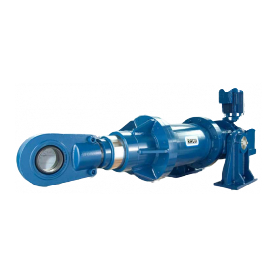
Actuator Type: T6C2
RACO-ELEKTRO-MASCHINEN GmbH
Jesinghauser Str. 56-64
58332 Schwelm / Germany
Tel.
+49 2336 4009-0
Fax
+49 2336 4009-10
E-Mail
RACO@raco.de
Internet www.raco.de
Contents
1 / 2
1190642-0010/162-407-5
Advertisement

Summary of Contents for Raco Schwelm T6C2
- Page 1 TECHNICAL DOCUMENTATION Translation of the original instruction Order : 1190642-0010 Part No.: 162-407-5 Actuator Type: T6C2 RACO-ELEKTRO-MASCHINEN GmbH Jesinghauser Str. 56-64 58332 Schwelm / Germany Tel. +49 2336 4009-0 +49 2336 4009-10 E-Mail RACO@raco.de Internet www.raco.de Contents 1 / 2...
-
Page 2: Table Of Contents
Document Doc.-No. Contents and technical data Operating Instructions Compact + Size 2 154-457-8 Maintenance Instruction Size 2, Compact 2-7 154-539-6 Description of the RACO - Motor Size 2 154-546-9 Description Position Sensoric EPS02 154-625-2 5.2.1 Wiring Example EPS 02 160-545-3... -
Page 3: Operating Instructions Compact + Size 2
Operating Instructions Compact + Size 2... - Page 4 2.2 Operating Instructions This operating instruction is relevant for the RACO-electric actuator type 6 / Compact series in size 2,4,6,7 and for the type T1A2 / T1B2. This documentation addresses to assemblers and (plant) operators. It contains important information on how to mount, operate, inspect and disassembly the product, as well as how to clear simple troubles on your own.
- Page 5 RACO supplies its products in accordance with agreed delivery conditions by means of drawings, spe- cifications and other data. RACO only check the suitability of the product for the purpose intended by the purchaser if this has been expressly agreed, and provided that the purchaser provides the necessary written information.
- Page 6 - ulations on safety and accident prevention. If RACO electrical cylinders are used for the lifting or transport of people, or are installed in machinery and systems that fulfil such a purpose, the equipment manufacturer is responsible for observing the special regulations applying to such equipment.
- Page 7 2.2.1.4 Qualification All work on RACO electrical cylinders may be carried out only by suitably trained specialist techni- cians. Such persons must be authorised by the system operator, must have read and understood the operating instructions, and must follow these instructions at al times.
- Page 8 6 in size 6 angle design C The RACO electrical cylinder is used for the moving and positioning of a mass in the linear direction. When power is fed to the motor, the rotary movement of the motor is converted into linear movement of the push/pull tube by means of the spindle/nut system.
- Page 9 In case of overload. For switching off in case of an overload, the motor must be thermally protected. RACO electric motors are fitted with a thermo-contact or a posistor temperature sensor, which signals any excessive motor temperature to the system controls.
- Page 10 If the safety symbol on the RACO electrical cylinder is covered or becomes illegible due to dirt or weather effects, clean the safety symbol or apply a new one.
- Page 11 Transport: 2.2.2.4 Storage If the RACO electrical cylinder is not to be installed immediately, it must be stored horizontally, in a dry area, and protected from impacts and the effects of weather. Bare metal areas must be protected with grease or oil, and the push/pull tube must be retracted.
- Page 12 Do not linger in hazard area below product. Installation sequence In order to ensure the long working life and smooth operation of the RACO electrical cylinder, care must be taken to follow the installation instructions exactly. The installation sequence is very import- ant, and must be followed.
- Page 13 – when the cylinder is completely extended or retracted. If the thrust tube can only be connected with the actuator after the RACO electrical cylinder has – been extended, this step is only carried out after the electrical installation of motor and limit switch.
- Page 14 (e.g. EPS06 with rpm monitoring feature). If a different motor variant is used in place of the RACO 3-phase motor, see the respective separate technical description. Connection and adjustment of the different device attachments (limit switch on the RACO motor, prox- imity switch, potentiometer, angle of rotation sensor converter / type DMU, path sensors / type: EPS, angular momentum sensors / type: DIG) must be carried out according to the respective instructions.
- Page 15 Using a suitable measuring device, check that the RACO electrical cylinder is correctly aligned. If the RACO electrical cylinder is not correctly aligned, you must use other suitable methods to align the RACO electrical cylinder correctly.
- Page 16 The precise approach of final and intermediate positions cannot be exactly reproduced under chan- ging operating conditions in the case of RACO electrical cylinders with self-locking trapezoidal thread spindles. It can fluctuate from a few millimetres to a few centimetres, depending on the run-in state between spindle and nut, the condition of the lubricant and the load.
- Page 17 0.05 mm. Ensure that the RACO electrical cylinder cannot run on and butt up against the mechanical end-stop in the cylinder. If an accurate position is to be reached by the end-position switch, a stop or similar device must be used.
- Page 18 2.2.6 Maintenance To prevent problems, hazards and damage, RACO electrical cylinders must be checked for proper function at regular intervals depending on the operating conditions. The area between the stripper (guide cap) and the thrust tube that moves in relation to this must be cleaned in particular to carry out a visual inspection for damage.
- Page 19 Notice! Damage caused by use of dissolver and aggressive cleaning supplies! Destruction of gaskets and malfunction of product. Only use water and mild cleaning supplies for cleaning. Close all openings with appropriate protection caps. Make sure all gaskets and closures are tight in order to avoid intrusion of wetness when cleaning, To increase durability of the gasket put some lubrication on the thrust tube in the area of the gasket after cleaning.
- Page 20 2.2.8 Accessories The RACO electrical cylinder can be extended with a wide range of accessories. Further information on our accessories can be found on the Internet under www.raco.de or by tele- phone from +49 2336 4009-0. Note! Accessories for the control of the end-position switches and for the motor can be found in the appendix to these operating instructions.
-
Page 21: Maintenance Instruction Size 2, Compact
Maintenance Instruction Size 2, Compact 2-7... - Page 22 Regular maintenance and care will increase the service life of your RACO electric cylinder. Mainten- ance depends on the field of application and environmental conditions. RACO electric cylinders of the 6 COMPACT series have a sealing ring between the thrust tube and the protective tube which prevents the penetration of water, dust and humidity.
- Page 23 Note on "motor attachment provided by the customer"! If electric cylinders are supplied as a thrust-retraction unit (i.e. without motor) the specifications for the attachment elements must be agreed with RACO. (motor type, reduction of the belt drive etc.) 3.2-2/3 Revision: 01...
- Page 24 M5 = SW 2.5 for T6C4-105 & T6C4-140)! If the motor has a RACO position sensor of the type EPS, the positions are still stored even after belt damage. There are two possible ways of aligning the switch position with the thrust-retraction tube...
-
Page 25: Description Of The Raco - Motor Size 2
Description of the RACO - Motor Size 2... - Page 26 Description of the RACO – Motor RACO offers three-phase motors, in 2- or 4-pole design with a power from 0,1kW up to 0,7kW. Every RACO motor is equipped with thermal contact (optional with thermistor) and can be used limited in combination with a frequency inverter.
- Page 27 Wiring Diagram for the RACO three-phase motor Wiring Diagram for the RACO single-phase motor The RACO Motor can be operated via capacitor at 1 phase AC (Steinmetz). Please note that in this mode only a small number of starts and a significant reduction is expected.
- Page 28 DANGER! Caution! Risk of damage! When connecting the motor, consider the movement direction of the thrust tube, as this may damage the RACO electric cylinder. Test the movement direction in the inching mode / operation. CAUTION! Danger from electric current or voltage!
- Page 29 Options: RACO 3-phase motor with RACO stroke sensoric type EPS06 RACO 3-phase motor with RACO stroke sensoric type EPS02 RACO 3-phase motor with mechanical limit switches RACO 3-phase motor with impuls encoder type DIG 4.2 - 4 / 5 Revision: 02...
- Page 30 RACO offers the three phase motors and electric equipment in different protection classes. Degrees of protection provided by enclosures (IP Code) DIN EN 60529 (VDE 0470-1). The RACO – DC-Motors are serially provided in protection class IP40. If required, a higher protection class can be provided, too.
-
Page 31: Description Position Sensoric Eps02
Description Position Sensoric EPS02... - Page 32 The electronic position sensor EPS02 is integrated in the additional device housing at the second end of the motor shaft of the RACO motor or in the lateral additional box on the coupling housing (when motors with a hand wheel or without sensor interface are used).
- Page 33 5.2.3 Electric connection The module has a four-pin connection plug for the relay contacts (right-hand plug) and a five-pin con- nection plug for voltage and signal connection (left-hand plug). For more information refer to wiring diagram 145-185-5 or 145-188-0 for DC-motors. 5.2.3.1 Voltage plug X1 The supply voltage, temperature protection and optional reference switch are connected here.
- Page 34 5.2.4 Technical data 24V DC +20 –30% Supply voltage UB: Relay outputs direction A/B: 250V AC/5A, 30VDC/5A Temperature monitor: on board 24V DC +20 – 30% Digital inputs, 1 psc.: 1% Accuracy: Data stored using Li battery 1.2 Ah: 10 years Temperature range: -40°C to +85°C Protective rating:...
- Page 35 5.2.6 Limit switch setting 5.2.6.1 Manual setting by on-board buttons The module can be configured by using the two buttons on the board. This is only necessary if there are changes to the cylinder, the installation situation or the area of application, or during repairs and maintenance.
- Page 36 Now keep button S1 pressed for longer than 1 second. You will now leave the set-up mode completely and change to normal operation mode. Note: A Windows RACO Setup Tool is optionally available to configure all functions of the EPS02. This software tool is available from RACO on data carriers (143-833-6) or in the download area of our website.
- Page 37 To change the parameters, after a successful connection to the PC, the param- eters are first read from the EPS02 via the button "Read parameter block" in the RACO Setup Tool. Modified parameters are restored via the "Send parameter block" in the EPS02.
- Page 38 Set zero position: The absolute position will be set to 0mm. Read Parameter Block: Parameters from the EPS02 will be send to the RACO Tool. Send Parameter Block: Parameters from the RACO Tool will be saved in the EPS02. Absolute position: The actual position of the actuator is shown.
- Page 39 Digital Output Configuration: Output 1 + 2 (X2.1 - X2.4): Here up to 8 switching cams can be set (in the example 10 and 990 mm). With the button (ON/OFF) the respective output can be set on or off. Hysteresis: The selected hysteresis number provides a negative and positive band around the selected switching point.
- Page 40 The parameterization may only be performed by specialist personnel. WARNING! First, the current position of the cylinder in the RACO Tool has to be stored. Therefore press in the “Setup” menu the function „Memory Position (old module)”. The position will be stored.
- Page 41 Note the displayed COM_Ports that are assigned to the driver and select one of these in the RACO Setup Tool under SETUP / COM port. Should an error occur, please choose another one. Attention: Use COM ports below port 10. Then the connection should be made and change the LED to the color green.
- Page 42 5.2.8 Waste disposal Please comply to the regional and national regulations when disposing of RACO electric actuators. For further recycling, reusable materials should be separated. Notice! Pollution of the environment The RACO Sensors contain the following materials: copper, terne met- al, bronze, plastic and electronic components.
-
Page 43: Wiring Example Eps 02
5.2.1 Wiring Example EPS 02... - Page 44 RACO- AC/DC 24V/10W ( - ) +24V S(In) S(Out) RACO motor Batterie EPS02 Datum Name Page Position Sensor EPS 02 R.Muhs 22.02.2016 Zchng.Nr. Klass. RACO 160-337-0 D24-000...
- Page 45 RACO- AC/DC 24V/10W ( - ) +24V S(In) S(Out) RACO motor brake r e c t i f y Batterie EPS02 Datum Name Page Position Senor EPS 02 R.Muhs 22.02.2016 Zchng.Nr. Klass. RACO 160-337-0 D24-000...
-
Page 46: Ec Installation Declaration
EC Installation Declaration... -
Page 48: Dimensional Drawing
Dimensional drawing...
Need help?
Do you have a question about the Schwelm T6C2 and is the answer not in the manual?
Questions and answers