Table of Contents
Advertisement
Quick Links
Advertisement
Table of Contents

Related Manuals for Siemens SIMOTICS T-1FW3


Summary of Contents for Siemens SIMOTICS T-1FW3
- Page 1 1FW3 complete torque motors...
- Page 3 Introduction Fundamental safety instructions Description of the motor SIMOTICS Mechanical properties Drive technology 1FW3 complete torque motors Motor components and options Configuration Configuration Manual Technical data and characteristics Preparation for use Electrical connection Installation drawings/Dimension drawings Appendix 08/2020 A5E46027705B AA...
- Page 4 Note the following: WARNING Siemens products may only be used for the applications described in the catalog and in the relevant technical documentation. If products and components from other manufacturers are used, these must be recommended or approved by Siemens. Proper transport, storage, installation, assembly, commissioning, operation and maintenance are required to ensure that the products operate safely and without any problems.
-
Page 5: Introduction
Introduction Standard scope This documentation describes the functionality of the standard scope. The machine manufacturer documents the supplements and changes made by the machine manufacturer. For reasons of clarity, this documentation cannot include all of the detailed information on all of the product types. - Page 6 Products (http://www.siemens.com/motioncontrol) My support Information on how to produce individual contents for your own machine documentation based on Siemens contents is available under the link: My support (https://support.industry.siemens.com/My/ww/en/documentation) Note If you want to use this function, you must register once.
- Page 7 Technical support (https://support.industry.siemens.com/sc/ww/en/sc/2090) Websites of third parties This publication contains hyperlinks to websites of third parties. Siemens does not take any responsibility for the contents of these websites or adopt any of these websites or their contents as their own, because Siemens does not control the information on these websites and is also not responsible for the contents and information provided there.
- Page 8 Introduction 1FW3 complete torque motors Configuration Manual, 08/2020, A5E46027705B AA...
-
Page 9: Table Of Contents
Table of contents Introduction ..............................3 Fundamental safety instructions ......................11 General safety instructions ..................... 11 Equipment damage due to electric fields or electrostatic discharge ........15 Security information ........................ 16 Residual risks of power drive systems ..................17 Description of the motor ........................... 19 Highlights and benefits ...................... - Page 10 Safety notes for mechanical mounting ................. 109 5.4.2 Overview of the mounting options ..................110 5.4.3 Plug-on installation ....................... 114 5.4.3.1 Siemens torque arm ......................115 5.4.3.2 Shaft-side clamping element ....................125 5.4.4 Coupling mounting ....................... 137 5.4.5 No bearings at the DE ......................138 5.4.6...
- Page 11 Table of contents Data sheets and characteristics .................... 162 6.3.1 Shaft height 150 ........................163 6.3.2 Shaft height 200, Standard ....................193 6.3.3 Shaft height 200, High Speed ....................229 6.3.4 Shaft height 280, Standard ....................253 6.3.5 Shaft height 280, High Speed ....................269 Preparation for use ..........................
- Page 12 Table of contents 1FW3 complete torque motors Configuration Manual, 08/2020, A5E46027705B AA...
-
Page 13: Fundamental Safety Instructions
Fundamental safety instructions General safety instructions WARNING Electric shock and danger to life due to other energy sources Touching live components can result in death or severe injury. • Only work on electrical devices when you are qualified for this job. •... - Page 14 Fundamental safety instructions 1.1 General safety instructions WARNING Electric shock due to damaged motors or devices Improper handling of motors or devices can damage them. Hazardous voltages can be present at the enclosure or at exposed components on damaged motors or devices. •...
- Page 15 • Therefore, if you move closer than 20 cm to the components, be sure to switch off radio devices or mobile telephones. • Use the "SIEMENS Industry Online Support app" only on equipment that has already been switched off. WARNING Unrecognized dangers due to missing or illegible warning labels Dangers might not be recognized if warning labels are missing or illegible.
- Page 16 Fundamental safety instructions 1.1 General safety instructions Note Important safety notices for Safety Integrated functions If you want to use Safety Integrated functions, you must observe the safety notices in the Safety Integrated manuals. WARNING Active implant malfunctions due to electromagnetic fields Electromagnetic fields (EMF) are generated by the operation of electrical power equipment, such as transformers, converters, or motors.
-
Page 17: Equipment Damage Due To Electric Fields Or Electrostatic Discharge
Fundamental safety instructions 1.2 Equipment damage due to electric fields or electrostatic discharge WARNING Fire due to incorrect operation of the motor When incorrectly operated and in the case of a fault, the motor can overheat resulting in fire and smoke. This can result in severe injury or death. Further, excessively high temperatures destroy motor components and result in increased failures as well as shorter service lives of motors. -
Page 18: Security Information
Siemens’ products and solutions undergo continuous development to make them more secure. Siemens strongly recommends that product updates are applied as soon as they are available and that the latest product versions are used. Use of product versions that are no longer supported, and failure to apply the latest updates may increase customer’s exposure... -
Page 19: Residual Risks Of Power Drive Systems
Fundamental safety instructions 1.4 Residual risks of power drive systems Residual risks of power drive systems When assessing the machine- or system-related risk in accordance with the respective local regulations (e.g., EC Machinery Directive), the machine manufacturer or system installer must take into account the following residual risks emanating from the control and drive components of a drive system: 1. - Page 20 Fundamental safety instructions 1.4 Residual risks of power drive systems 1FW3 complete torque motors Configuration Manual, 08/2020, A5E46027705B AA...
-
Page 21: Description Of The Motor
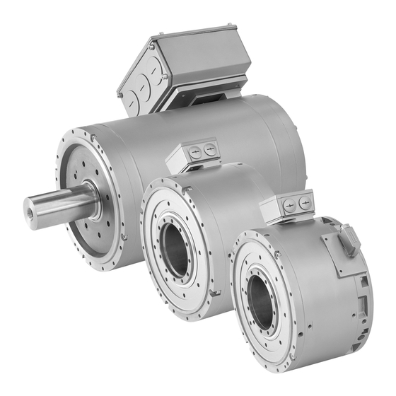
Description of the motor Overview of the standard SIMOTICS T-1FW3 complete torque motors The 1FW3 series was developed as direct drive. This direct drive is a compact drive unit where the mechanical motor power is transferred directly to the driven machine without any mechanical transmission elements. - Page 22 Figure 2-1 Complete 1FW3 Heavy Duty torque motor Siemens is offering, with the complete 1FW3 Heavy Duty torque motor, a direct drive that addresses the following requirements. The powerful, permanent-magnet synchronous motor is characterized on the one hand by its high dynamic response and precision.
-
Page 23: Highlights And Benefits
Description of the motor 2.1 Highlights and benefits Easy to integrate ● in the mechanical system ● in the SINAMICS S120 drive system (DRIVE-CLiQ interface) Complete 1FW3 Heavy Duty torque motor – brief overview of the technology Rated speed:* up to 800 rpm (maximum speed up to 1380 rpm) Rated torque:* up to 7000 Nm (maximum torque up to 11400 Nm) * depending on the version and type... -
Page 24: Use For The Intended Purpose
Where relevant, take into account deviations regarding approvals or country-specific regulations. • Contact your local Siemens office if you have any questions relating to correct use. • If you wish to use special versions and design versions whose technical details vary from the motors described in this document, then you must contact your local Siemens office. -
Page 25: Technical Features And Environmental Conditions
Description of the motor 2.3 Technical features and environmental conditions ● Roll drives in paper machines ● Cross-cutter drives for continuous material webs, e.g. paper, textiles, metal sheet ● Wire-drawing machines ● Chippers WARNING Injury and material damage by not observing machinery directive 2006/42/EC There is a risk of death, serious injury and/or material damage if machinery directive 2006/42/EC is not carefully observed. - Page 26 SIMOTICS motors do not fall within the scope covered by the China Compulsory Certification (CCC). CCC negative certification: CCC product certification (https://support.industry.siemens.com/cs/products?search=CCC&dtp=Certificate&mfn=ps&o =DefaultRankingDesc&pnid=13347&lc) China RoHS SIMOTICS motors comply with the China RoHS. You can find additional information at: China RoHS (https://support.industry.siemens.com/cs/ww/en/view/109738656) 1FW3 complete torque motors Configuration Manual, 08/2020, A5E46027705B AA...
-
Page 27: Torque Overview
Quality systems Siemens AG employs a quality management system that meets the requirements of ISO 9001 and ISO 14001. Certificates for SIMOTICS motors can be downloaded from the Internet at the following link: Certificates for SIMOTICS motors (https://support.industry.siemens.com/cs/ww/en/ps/13347/cert) -
Page 28: Technical Features
Standard DE fixed bearing; NDE floating bearing: Roller bearings with • permanent grease lubrication (bearing change interval = 20000h) DE no bearing can be selected • Mounting set Siemens torque arm • Clamping elements • 1FW3 complete torque motors Configuration Manual, 08/2020, A5E46027705B AA... - Page 29 Sensor hole M8; DE and NDE • Manufacturer's test certificate • Q30 clamping elements • Siemens torque arm • S/R = Signals/Revolution Dimension drawings You can find the dimension drawings for the motors in Chapter "Dimension drawings (Page 315)". 1FW3 complete torque motors...
-
Page 30: Environmental Conditions
With the exception of "Condensation" and "Low air pressure" environmental parameters, you can assign SIMOTICS T-1FW3 complete torque motors to climatic class 3K4. Condensation and expansion of the temperature range are not permissible. -
Page 31: Derating Factors
Description of the motor 2.4 Derating factors Note Unsuitable installation locations The motors are not suitable for operation • in salt-laden or corrosive atmospheres • outdoors The motors are designed for operation in covered areas, such as production facilities. Derating factors Derating for the maximum DC link voltage At installation altitudes of 2000 m above sea level or higher, the voltage stress on the motors must be reduced accordingly based on the table below (reciprocal values from EN 60664-1... -
Page 32: Selection And Ordering Data
Description of the motor 2.5 Selection and ordering data Selection and ordering data The data in the following tables refer to operation with an ALM (Active Line Module) and a 600 V DC link voltage. The specified efficiency η is a typical value, theoretically determined and which has its optimum in the continuous operation range. - Page 33 Description of the motor 2.5 Selection and ordering data Table 2- 7 Technical data, 1FW320☐ High Speed Motor type η max mech. [rpm] [Nm] [kW] [Nm] [rpm] 1FW3201-3☐P 20.5 1800 1FW3201-3☐S 1200 29.0 1800 1FW3202-3☐P 39.5 1800 1FW3202-3☐S 1200 1800 1FW3203-3☐P 1210 1800...
- Page 34 Motor Modules. Note Configuration tool The SIZER for SIEMENS Drives engineering tool supports you when dimensioning and engineering the drive system (see Chapter "SIZER configuration tool (Page 91)"). Structure of the Article Nos. for the Motor Modules Suitable Motor Module...
- Page 35 Description of the motor 2.5 Selection and ordering data Motor type Rated current / Order designation (Article No.) Rated current Rated pulse frequency stall current Motor Module SINAMICS S120 Motor Module Motor [A] / I [kHz] pulseN Line supply voltage of 400 V 3 AC, Active Line Module (V = 425 V) 1FW320☐...
- Page 36 Description of the motor 2.5 Selection and ordering data Motor type Rated current / Order designation (Article No.) Rated current Rated pulse frequency stall current Motor Module SINAMICS S120 Motor Module Motor [A] / I [kHz] pulseN Line supply voltage of 400 V 3 AC, Active Line Module (V = 425 V) 1FW3287-2☐E 230 / 234...
- Page 37 Description of the motor 2.5 Selection and ordering data Order designation Note Note that not every theoretical combination is possible in practice. 1FW3 complete torque motors Configuration Manual, 08/2020, A5E46027705B AA...
-
Page 38: Rating Plate Data
Description of the motor 2.6 Rating plate data Rating plate data The rating plate refers to the technical data of the motor. Table 2- 11 Description of the rating plate data Position Description / Technical specifications Motor type: Synchronous motor, complete torque motor, Article No. Additional information Type of construction Static torque [Nm]... -
Page 39: Mechanical Properties
Mechanical properties Cooling WARNING Defective work on the cooling circuit Defective work on the cooling circuit can cause injury and/or damage to property. • Only qualified personnel may assemble, install, and commission the cooling circuit. • Perform installation or service work on the cooling circuit only when the system is de- energized. - Page 40 Mechanical properties 3.1 Cooling Note Cooling circuits Only closed and semi-open cooling circuits are permissible for motors. Converter systems must be connected before the motors in the cooling circuit. Figure 3-1 Example of a semi-open cooling circuit Equipotential bonding WARNING Electric shock as a result of incorrectly routing the cooling water pipes If electrically conductive cooling water pipes come into contact with live parts, this can cause an electric shock leading to death or severe injury.
- Page 41 Mechanical properties 3.1 Cooling Materials used in the motor cooling circuit The materials used in the cooling circuit must be coordinated with the materials in the motor. Materials used in the motor (cooling jacket material): E355 AR (1.0580), DD11 (1.0332) Materials and components in the cooling circuit Note Minimizing electrochemical processes in the cooling circuit...
- Page 42 Mechanical properties 3.1 Cooling Material Used as Description Gaskets Pipes, valves and Use of FPM (Viton), AFM34, EPDM is recommended. fittings Hose connections Transition Secure with clips conforming to DIN EN 14420, available, e.g. from Hose - pipe Telle. The following recommendation applies in order to achieve an optimum motor heatsink (enclosure) service life: ●...
-
Page 43: Pressure Conditions In The Cooling Circuit
Mechanical properties 3.1 Cooling 3.1.2 Pressure conditions in the cooling circuit Consider the following pressure conditions when designing the cooling circuit. Permissible pressure ● Define the working pressure based on the flow conditions in the supply and return pipes of the cooling circuit. The maximum permitted pressure in the cooling circuit is 0.6 MPa (6 bar). - Page 44 0.92 Note Cooling water inlet temperatures > 45 °C Contact your local Siemens office for cooling water inlet temperatures > 45 °C. The following data are required to answer your inquiry about derating due to increased ambient temperatures: • Ambient temperature in °C •...
- Page 45 Mechanical properties 3.1 Cooling Note Independence of derating factors For water cooling, the derating factors are independent of the installation altitude. • The ambient conditions change with increasing installation altitude. As a consequence, ensure that the required cooling water inlet temperature is available for the cooling system.
- Page 46 Mechanical properties 3.1 Cooling Motor type Cooling power to be dissipated Pressure loss Cooling flow rate in l/min Δp in kW in bar SH 280 High Speed 1FW3281-3 11.0 1FW3283-3 10.3 13.0 1FW3285-3 13.8 16.0 1FW3287-3 18.9 20.0 Figure 3-2 Flow rate for SH 150 1FW3 complete torque motors Configuration Manual, 08/2020, A5E46027705B AA...
- Page 47 Mechanical properties 3.1 Cooling Figure 3-3 Flow rate for SH200 Figure 3-4 Flow rate for SH280 1FW3 complete torque motors Configuration Manual, 08/2020, A5E46027705B AA...
- Page 48 Mechanical properties 3.1 Cooling Coolant volume of the motor Table 3- 5 Coolant volume of the motor Length (7 position Coolant volume of the motor (liters) in the Article No.) 1FW315 1FW320 1FW328 Hollow shaft Plug-on shaft Solid shaft 0.23 0.11 0.11 0.33...
-
Page 49: Cooling Water
Mechanical properties 3.1 Cooling 3.1.3 Cooling water Table 3- 6 Water specification as coolant Quality of the water used as coolant for motors with alumi- num, stainless steel tubes + cast iron or steel jacket Chloride ions < 40 ppm, can be achieved by adding deionized water. Sulfate ions <... - Page 50 This document contains recommendations relating to third-party products. Siemens accepts the fundamental suitability of these third-party products. You can use equivalent products from other manufacturers. Siemens does not accept any warranty for the properties of third-party products. 1FW3 complete torque motors Configuration Manual, 08/2020, A5E46027705B AA...
-
Page 51: Cooling Water Connection
Mechanical properties 3.1 Cooling 3.1.4 Cooling water connection On the side of the motor there are 2 internal threads for the motor connection to the cooling circuit. The intake and discharge lines can be connected as required. We recommend the intake at the NDE. -
Page 52: Degree Of Protection
Mechanical properties 3.2 Degree of protection Degree of protection The degree of protection is defined according to EN 60034-5 (IEC 60034-5) (e.g. IP65). The degree of protection is stamped on the rating plate. The combination of letters and numbers has the following significance: ●... -
Page 53: Bearing Version
Mechanical properties 3.4 Bearing version Bearing version The bearings for the complete torque motors are greased for life and designed for a minimum ambient temperature in operation of -15 °C. Table 3- 8 Bearing designation and bearing properties for the normal version with standard bearings Shaft version Basis bearing designation SH 150... -
Page 54: Radial And Axial Forces
Mechanical properties 3.6 Radial and axial forces Table 3- 11 Solid shaft Frame size Shaft length l [mm] Shaft diameter d [mm] 1FW315☐ 65 m6 1FW320☐ 90 m6 1FW328☐ 120 m6 The shaft version "solid shaft" can be ordered with a plain shaft end or with keyway (according to DIN 6885-1). - Page 55 Mechanical properties 3.6 Radial and axial forces NOTICE Running inaccuracy and premature bearing failure With the types of construction IM V3, IM V19 and IM V35, the force imposed by the weight of the rotor and/or the force imposed by the weight of the customer attachment may impermissibly reduce or even nullify the spring work force of the DE bearing.
-
Page 56: Hollow Shaft
Mechanical properties 3.6 Radial and axial forces 3.6.1 Hollow shaft Radial force diagram for 1FW315❑ hollow shaft Figure 3-6 Radial force diagram for 1FW315❑, with nominal bearing change interval of 20000 h Axial force diagram for 1FW315❑ hollow shaft Figure 3-7 Permissible axial force as a function of radial force for 1FW315❑... - Page 57 Mechanical properties 3.6 Radial and axial forces Radial force diagram for 1FW320❑ hollow shaft Figure 3-8 Radial force diagram for 1FW320❑, with nominal bearing change interval of 20000 h Axial force diagram for 1FW320❑ hollow shaft Figure 3-9 Permissible axial force as a function of radial force for 1FW320❑ 1FW3 complete torque motors Configuration Manual, 08/2020, A5E46027705B AA...
- Page 58 Mechanical properties 3.6 Radial and axial forces Radial force diagram for 1FW328❑ hollow shaft Figure 3-10 Radial force diagram for 1FW328❑, with nominal bearing change interval of 20000 h Axial force diagram for 1FW328❑ hollow shaft Figure 3-11 Permissible axial force as a function of radial force for 1FW328❑ 1FW3 complete torque motors Configuration Manual, 08/2020, A5E46027705B AA...
-
Page 59: Plug-On Shaft
3.6.2 Plug-on shaft Note Using a torque arm For plug-on mounting (shaft mounting) we recommend that a Siemens torque arm is used (See Chapter "Siemens torque arm (Page 115)"). Radial force diagram for 1FW315❑ plug-on shaft Figure 3-12 Radial force diagram for 1FW315❑, with nominal bearing change interval of 20000 h Axial force diagram for 1FW315❑... - Page 60 Mechanical properties 3.6 Radial and axial forces Radial force diagram for 1FW315❑ plug-on shaft Figure 3-14 Radial force diagram for 1FW315❑, with nominal bearing change interval of 60000 h Axial force diagram for 1FW315❑ plug-on shaft Figure 3-15 Permissible axial force as a function of radial force for 1FW315❑ (60000 h) 1FW3 complete torque motors Configuration Manual, 08/2020, A5E46027705B AA...
- Page 61 Mechanical properties 3.6 Radial and axial forces Radial force diagram for 1FW320❑ plug-on shaft Figure 3-16 Radial force diagram for 1FW320❑, with nominal bearing change interval of 20000 h Axial force diagram for 1FW320❑ plug-on shaft Figure 3-17 Permissible axial force as a function of radial force for 1FW320❑ (20000 h) 1FW3 complete torque motors Configuration Manual, 08/2020, A5E46027705B AA...
- Page 62 Mechanical properties 3.6 Radial and axial forces Radial force diagram for 1FW320❑ plug-on shaft Figure 3-18 Radial force diagram for 1FW320❑, with nominal bearing change interval of 60000 h Axial force diagram for 1FW320❑ plug-on shaft Figure 3-19 Permissible axial force as a function of radial force for 1FW320❑ (60000 h) For motors 1FW328❑...
-
Page 63: Solid Shaft
Mechanical properties 3.6 Radial and axial forces 3.6.3 Solid shaft Radial force diagram for 1FW315❑ solid shaft Figure 3-20 Radial force diagram for 1FW315❑, with nominal bearing change interval of 20000 h Axial force diagram for 1FW315❑ solid shaft Figure 3-21 Permissible axial force as a function of radial force for 1FW315❑... - Page 64 Mechanical properties 3.6 Radial and axial forces Radial force diagram for 1FW315❑ solid shaft Figure 3-22 Radial force diagram for 1FW315❑, with nominal bearing change interval of 60000 h Axial force diagram for 1FW315❑ solid shaft Figure 3-23 Permissible axial force as a function of radial force for 1FW315❑ (60000 h) 1FW3 complete torque motors Configuration Manual, 08/2020, A5E46027705B AA...
- Page 65 Mechanical properties 3.6 Radial and axial forces Radial force diagram for 1FW320❑ solid shaft Figure 3-24 Radial force diagram for 1FW320❑, with nominal bearing change interval of 20000 h Axial force diagram for 1FW320❑ solid shaft Figure 3-25 Permissible axial force as a function of radial force for 1FW320❑ (20000 h) 1FW3 complete torque motors Configuration Manual, 08/2020, A5E46027705B AA...
- Page 66 Mechanical properties 3.6 Radial and axial forces Radial force diagram for 1FW320❑ solid shaft Figure 3-26 Radial force diagram for 1FW320❑, with nominal bearing change interval of 60000 h Axial force diagram for 1FW320❑ solid shaft Figure 3-27 Permissible axial force as a function of radial force for 1FW320❑ (60000 h) 1FW3 complete torque motors Configuration Manual, 08/2020, A5E46027705B AA...
- Page 67 Mechanical properties 3.6 Radial and axial forces Radial force diagram for 1FW328❑ solid shaft Figure 3-28 Radial force diagram for 1FW328❑, with nominal bearing change interval of 40000 h Axial force diagram for 1FW328❑ solid shaft Figure 3-29 Permissible axial force as a function of radial force for 1FW328❑ (40000 h) 1FW3 complete torque motors Configuration Manual, 08/2020, A5E46027705B AA...
-
Page 68: Balancing
Mechanical properties 3.7 Balancing Balancing Requirements placed on the balancing process for mounted components Motors with hollow shaft and plug-on shaft must be balanced in the factory without any mounted components. Motors with solid shaft are balanced according to DIN ISO 21940-32. In addition to the balance quality of the motor, the vibration quality of motors with mounted output elements is essentially determined by the balance quality of the mounted component. - Page 69 Condition-monitoring-ready motors are equipped with boreholes for inserting vibration sensors. This allows you to position vibration sensors optimally and install condition monitoring systems. You can find further information about the Siemens condition monitoring system by following this link: SIPLUS CMS (https://new.siemens.com/global/en/products/automation/products-for-specific-...
-
Page 70: Noise Emission
Mechanical properties 3.9 Noise emission Noise emission WARNING Hearing damage Hearing damage may occur if the motor exceeds a sound pressure level of 70 dB (A) due to the type of mounting or pulse frequency. • Reduce the sound pressure level by implementing sound damping and/or soundproofing measures. -
Page 71: Bearing Change Intervals
Mechanical properties 3.10 Bearing change intervals 3.10 Bearing change intervals Bearing lifetime and regreasing interval The bearings for the complete torque motors are greased for life and designed for operation at a minimum ambient temperature of - 15 °C. Note Bearings without regreasing system For bearings without regreasing system (SH 150 and SH 200), we recommend that the bearings are replaced after approx. - Page 72 Mechanical properties 3.10 Bearing change intervals Motor Bearing change interval with re- Regreasing intervals [h] greasing [h] 1FW328❑-3 n = 800 hollow shaft 40000 8000 1FW328❑-2/3 plug-on shaft 40000 8000 1FW328❑-2 n = 150/250 solid 40000 10000 shaft 1FW328❑-3 n = 400 solid shaft 40000 8000...
- Page 73 Special versions Unfavorable factors (e.g. effects of mounting/installation, speeds, special modes of operation or high mechanical loads) may require special measures. Contact your local Siemens office, specifying the prevailing general conditions. 1FW3 complete torque motors Configuration Manual, 08/2020, A5E46027705B AA...
-
Page 74: Maintenance And Service Intervals
Mechanical properties 3.11 Maintenance and service intervals 3.11 Maintenance and service intervals 3.11.1 Maintenance intervals General Regularly carry out maintenance work, inspections and revisions/overhauls in order to identify and resolve faults at an early stage - before these result in subsequent damage. WARNING Faults or unusual conditions Faults or unusual conditions when operating the motor can result in death, severe injury or... -
Page 75: Checking The Cooling Water
Additional regional motor repair centers will be successively authorized in order to minimize downtimes and to be able to perform repairs quickly, at a favorable price and with a high quality standard. For contact data of the Siemens Service Center, see "Technical Support" in Chapter "Introduction". 3.11.2 Checking the cooling water ●... - Page 76 Mechanical properties 3.11 Maintenance and service intervals 1FW3 complete torque motors Configuration Manual, 08/2020, A5E46027705B AA...
-
Page 77: Motor Components And Options
Motor components and options Motor components 4.1.1 Thermal motor protection NOTICE Thermal motor damage Windings and bearings can be destroyed if the motor overheats. Further, if a motor overheats, this can demagnetize the permanent magnets. • Only operate the motors in conjunction with an effective temperature control. Thermal motor protection with temperature sensors The stator core has two temperature sensors to monitor the winding;... - Page 78 Motor components and options 4.1 Motor components Reserve with plug-in connection in the insulating tubing Reserve Connected temperature sensor Figure 4-2 Example: Connection in the terminal box Two temperature sensor types are integrated: KTY 84 Pt1000 Temperature sensors KTY 84 are ESD components. When Pt1000 temperature sensors are not ESD components.
- Page 79 Motor components and options 4.1 Motor components The following diagram shows the resistance characteristic as a function of the temperature for KTY 84-130 and Pt1000 temperature sensors. Figure 4-3 Comparison of KTY 84-130 and Pt1000 temperature sensors The prewarning signal from the evaluation circuit in the SINAMICS drive converter can be externally evaluated.
-
Page 80: Encoders
WARNING Uncontrolled motor motion as a result of incorrect adjustment The encoders are adjusted in the factory for SIEMENS drive converters. Another encoder adjustment may be required when operating the motor with a third-party converter. Incorrect adjustment of the encoder regarding motor EMF can lead to uncontrolled motion which can cause injury and material damage. - Page 81 Motor components and options 4.1 Motor components Note Replacing a coaxially mounted encoder When replacing a coaxially mounted encoder, you do not have to adjust the encoder system. The position with respect to the motor EMF is ensured using mechanical components. Encoder selection and identification in the Article No.
-
Page 82: Safety Integrated Functions
• Do not mount the DRIVE-CLiQ encoder onto other motors. • Do not replace a DRIVE-CLiQ encoder by a DRIVE-CLiQ encoder belonging to another motor. • Only appropriately trained Siemens service personnel should replace DRIVE-CLiQ encoders. NOTICE Damage to components that are sensitive to electrostatic discharge The DRIVE-CLiQ interface has direct contact to components that can be damaged/destroyed by electrostatic discharge (ESDS). -
Page 83: Encoder Connection For Motors Without Drive-Cliq Interface
CONNECTⓇ500 Max. cable length 50 m 8 MOTION- CONNECTⓇ800 Only prefabricated cables from Siemens (MOTION-CONNECT) may be used. For other technical data and length code, refer to Catalog D21.4, Chapter "MOTION- CONNECT connection system". 4.1.2.3 Encoder connection for motors without DRIVE-CLiQ interface For motors without an integrated DRIVE-CLiQ interface, the analog encoder signal in the drive system is converted into a digital signal. - Page 84 Motor components and options 4.1 Motor components Table 4- 5 Technical data for incremental encoders Encoder type 9th position Operating Max. current A-B track: Resolu- C-D track: Ro- Angular in the Article voltage drain tion incremental tor/commutation error (sin/cos periods per position (sin/cos revolution) periods per revolu-...
- Page 85 Motor components and options 4.1 Motor components Connection assignment for 17-pin signal connector PIN No. Signal Diagram M encoder +1R1 (KTY 84) or 1R1 (Pt1000) –1R2 (KTY 84) or 1R2 (Pt1000) P encoder 15 * M sense 16 * P sense Not connected Cable break and voltage control Cables...
-
Page 86: Absolute Encoders
Motor components and options 4.1 Motor components 4.1.2.5 Absolute encoders Description of multiturn absolute encoders This encoder outputs an absolute angular position between 0° and 360° in the specified resolution. An internal measuring gearbox enables the encoder to differentiate between 4096 revolutions. - Page 87 Motor components and options 4.1 Motor components Connection pin assignment for 17-pin flange socket with pin contacts Table 4- 8 Connection pin assignment, 17-pin flange socket PIN No. Signal Diagram Data Not connected Clock Not connected M encoder +1R1 (KTY 84) or 1R1 (Pt1000) –1R2 (KTY 84) or 1R2 (Pt1000)
-
Page 88: Multi-Pole Resolver
Motor components and options 4.1 Motor components 4.1.2.6 Multi-pole resolver Description The number of sine and cosine periods per revolution corresponds to the number of pole pairs of the resolver. Resolvers can detect relative motion. The absolute position within one resolver output signal period can be determined. - Page 89 Motor components and options 4.1 Motor components Connection pin assignment for 12-pin flange socket with pin contacts Table 4- 11 Connection pin assignment, 12-pin flange socket PIN No. Signal Fig. Not connected Not connected Not connected Not connected +1R1 (KTY 84) or 1R1 (Pt1000) –1R2 (KTY 84) or 1R2 (Pt1000)
-
Page 90: Encoder With Belt Drive
Motor components and options 4.1 Motor components 4.1.2.7 Encoder with belt drive The encoder in the encoder box (on the stator side) is coupled via a belt. This means, for example, the hollow shaft can be used to route media. Gear ratio, see the table "Ratio" in this Chapter. -
Page 91: Coaxial Encoder Mounting
Motor components and options 4.1 Motor components 4.1.2.8 Coaxial encoder mounting Coaxial encoder mounting is available for high dynamic requirements and the highest precision. The encoder module can be easily replaced without requiring readjustment. Further information can be found in Chapter "Removing/mounting the encoder (Page 143)." Figure 4-6 1FW3 with coaxially mounted encoder 4.1.2.9... -
Page 92: Options
Cable entry plate with 4 x M63 x 1.5 for 1XB7-712 terminal box Clamping elements Shaft cover at NDE for a hollow shaft Siemens torque arm Special grease for low speeds Paint finish, matt black RAL9005 paint finish Paint finish, cream white RAL9001... -
Page 93: Configuration
● Installation information of the drive and control components ● Energy considerations of the configured drive systems You can find additional information that you can download in the Internet at SIZER (https://support.industry.siemens.com/cs/ww/en/view/54992004). 5.1.2 STARTER drive/commissioning software The STARTER commissioning tool offers ●... -
Page 94: Configuring Workflow
Configuration 5.2 Configuring workflow Configuring workflow Motion Control Servo drives are optimized for motion control applications. They execute linear or rotary movements within a defined movement cycle. All movements should be optimized in terms of time. As a result of these considerations, servo drives must meet the following requirements: ●... -
Page 95: Clarify The Drive Type
Configuration 5.2 Configuring workflow 5.2.1 Clarify the drive type The motor is selected based on the required torque, which is defined by the application. Typical applications are, for example: ● Traversing drives ● Hoisting drives ● Test stands ● Centrifuges ●... -
Page 96: Define The Supplementary Conditions And Integrate The Drive Into The Automation System
Configuration 5.2 Configuring workflow 5.2.2 Define the supplementary conditions and integrate the drive into the automation system If high maximum speeds are to be reached, then induction motors can be used in the field weakening range. Induction motors are also suitable for higher power ratings. The drives should either be defined as single-axis drives or in a group as multi-axis drives. -
Page 97: Define The Load Case, Calculate The Maximum Torque, Select The Motor
Configuration 5.2 Configuring workflow 5.2.3 Define the load case, calculate the maximum torque, select the motor The motor-specific limiting curves are used as basis when selecting a motor. These define the torque characteristic with respect to speed and take into account the motor limits based on the line supply voltage and the function of the infeed. - Page 98 Configuration 5.2 Configuring workflow The objective is to identify characteristic torque and speed operating points, which can be used as a basis for selecting the motor depending on the load. Once the operating scenario has been defined and specified, the maximum motor torque is calculated.
- Page 99 Configuration 5.2 Configuring workflow Load duty cycles with constant on period For load duty cycles with constant on time, specific requirements are placed on the torque characteristic as a function of the speed e.g. M = constant, M ~ n , M ~ n or P = constant.
- Page 100 An overload must be taken into consideration for load duty cycles with varying on times. Note For duty cycles in the field weakening range, the SIZER for SIEMENS Drives engineering tool must be used. The following formulas can be used for duty cycles outside the field weakening range.
- Page 101 Configuration 5.2 Configuring workflow SINAMICS ALM 400 V line supply (600 V DC link voltage) M in Nm; n in rpm AP 1 = 400 Nm at 100 rpm AP 2 = 0 Nm at 0 rpm Figure 5-5 Selecting motors for load duty cycles with different on time 1FW3201-☐E☐ 1FW3 complete torque motors Configuration Manual, 08/2020, A5E46027705B AA...
- Page 102 Note For duty cycles in the field weakening range, the SIZER for SIEMENS Drives engineering tool must be used. The following formulas can be used for duty cycles outside the field weakening range.
- Page 103 Configuration 5.2 Configuring workflow Calculating the rms torque Calculating the medium motor speed Motor moment of inertia Gearbox moment of inertia Load moment of inertia load Load speed Load Gear ratio η Gearbox efficiency Load torque load Frictional torque Cycle time, clock cycle time Initial value, final value in time slice Δ...
- Page 104 Configuration 5.2 Configuring workflow In summary, the motor is selected as follows: SINAMICS ALM 400 V line supply (600 V DC link voltage) M in Nm; n in rpm Figure 5-7 Selecting motors according to the load duty cycle for motor 1FW3201-☐E☐ Motor selection By making the appropriate iterations, a motor can now be selected that precisely fulfills the operating conditions and application...
-
Page 105: Braking Resistors (Armature Short-Circuit Braking)
Configuration 5.3 Braking resistors (armature short-circuit braking) Finally, the other motor features must be defined This is realized by appropriately configuring the motor options. Braking resistors (armature short-circuit braking) 5.3.1 Function description Function description For transistor PWM converters, when the DC link voltage values are exceeded or if the electronics fails, then electrical braking is no longer possible. - Page 106 Configuration 5.3 Braking resistors (armature short-circuit braking) Figure 5-8 Circuit (schematic) with brake resistors Ordering address Frizlen GmbH & Co. KG Gottlieb-Daimler-Str. 61, 71711 Murr Germany Phone: +49 (0) 7144 / 8100 - 0 Fax: +49 (0) 7144 / 2076 - 30 E-mail: info@frizlen.com Internet at:...
- Page 107 Configuration 5.3 Braking resistors (armature short-circuit braking) Calculating the braking time Note When determining the run-on distance, the friction (taken into account as allowance in M ) of the mechanical transmission elements and the switching delay times of the contactors must be taken into consideration.
-
Page 108: Dimensioning Of Braking Resistors
Configuration 5.3 Braking resistors (armature short-circuit braking) 5.3.2 Dimensioning of braking resistors The correct dimensioning ensures an optimum braking time. The braking torques which are obtained are also listed in the tables. The data applies for braking from the rated speed. If the motor brakes from another speed, then the braking time cannot be linearly reduced. - Page 109 Configuration 5.3 Braking resistors (armature short-circuit braking) Table 5- 3 Dynamic braking 1FW3, SH 200 Standard and High Speed Motor type External Average braking torque Max. rms braking current braking [Nm] braking torque br av br rms resistor [Nm] br max without external with external without external...
- Page 110 Configuration 5.3 Braking resistors (armature short-circuit braking) Table 5- 4 Dynamic braking 1FW3, SH 280 Standard and High Speed Motor type Braking Average braking torque Max. braking rms braking current resistor torque [Nm] br av br rms external [Nm] br rms without external with external without external...
-
Page 111: Mounting
Configuration 5.4 Mounting Mounting 5.4.1 Safety notes for mechanical mounting WARNING Danger to life from permanent magnet fields Torque motor rotors are equipped with strong permanent magnets. This is the reason that when the motors are open there are strong magnetic fields and high magnetic forces of attraction. -
Page 112: Overview Of The Mounting Options
Configuration 5.4 Mounting NOTICE Thermal damage to temperature-sensitive parts The motors can have surface temperatures of over +100° C. Temperature-sensitive parts in contact with the motor or attached to the motor can be damaged. Temperature-sensitive parts include cables and electronic components, for example. •... - Page 113 Configuration 5.4 Mounting The torque motors are complete motors equipped with deep-groove ball bearings. NOTICE Motor bearing damage caused by overdetermined shaft bearings An overdetermined bearing system can result in immediate bearing damage or significantly reduce the bearing change interval. •...
- Page 114 Configuration 5.4 Mounting Mounting the motor frame to the machine on the customer's side You can mount the motor enclosure of the complete 1FW3 torque motor to the customer's machine corresponding to the following table: Table 5- 5 Types of construction Type of con- Designation Type of con-...
- Page 115 Configuration 5.4 Mounting Connecting the rotor to the drive shaft You can connect the rotor of the 1FW3 motor to the customer drive shaft either using a flange or a clamping element: Shaft height Threaded hole at the rotor DE (face side) Tensioning elements in the inner diameter of the rotor 12 x M12, 24 mm deep, pitch circle diameter ∅...
-
Page 116: Plug-On Installation
Configuration 5.4 Mounting 5.4.3 Plug-on installation Figure 5-12 Decoupling the stator from the machine base using a torque arm (schematic representation) For shaft mounting, the motor weight is solely carried by the shaft extension of the driven machine. The mounting to the motor frame cannot accept any cantilever forces and therefore does not support the motor. -
Page 117: Siemens Torque Arm
Siemens torque arm is subject to inadmissibly high cantilever forces. ● The motor can be vertically mounted when using Siemens torque arms. When attaching the torque arms it must be ensured that there is no axial deformation or distortion. - Page 118 (see Fig A), in addition to the two-mass system comprising the load and rotor (see Fig. B). The influence of the Siemens torque arm is shown qualitatively in the following diagram. The two-mass oscillating system comprising motor and load still dominates the system response;...
- Page 119 Configuration 5.4 Mounting Table 5- 7 Resonant frequency, stator coupling Motor Resonant frequency to be ex- Note pected [Hz] 1FW315☐ 1FW3150 1FW3151 1FW3152 1FW3153 1FW3154 1FW3155 1FW3156 1FW320☐ 1FW3201 1FW3202 Depending on the particular 1FW3203 application, the resonant fre- 1FW3204 quency can be up to 20% high- 1FW3206 1FW3208...
- Page 120 Configuration 5.4 Mounting Mounting sequence, Siemens torque arm with clamping element Procedure 1. Check the rotor and prepare the shaft seat: Clamping seat: must be free of any lubricant Centering seat: Apply assembly paste, e.g. Molykot Clamping screws (all of the screws shown in green in this diagram)
- Page 121 Configuration 5.4 Mounting 2. Axially slide the motor onto the customer's flange: ● The motor is slid onto the shaft extension and is in the correct axial position when the torque arm is located on the machine-side flange. The motor is not axially positioned on the shaft side.
- Page 122 Configuration 5.4 Mounting 3 window to tighten the screws Figure 5-17 Pre-mounting 3. Check the gap in the clamping element, and if required, measure the motor alignment (run out): ● The gap between the two clamping element parts must be able to be identified around the complete circumference.
- Page 123 Figure 5-18 Check 4. Mounting the Siemens torque arm: After successfully carrying out steps 1 – 3, screw the Siemens torque arm to the machine. Mounting screws (all of the screws shown in green in this diagram) Figure 5-19 Final mounting The motor has been mounted.
- Page 124 Configuration 5.4 Mounting Figure 5-20 1FW3150 Siemens torque arm, dimension drawing 510.20315.01 1FW3 complete torque motors Configuration Manual, 08/2020, A5E46027705B AA...
- Page 125 Configuration 5.4 Mounting Figure 5-21 1FW320 Siemens torque arm, dimension drawing 510.35320.01 1FW3 complete torque motors Configuration Manual, 08/2020, A5E46027705B AA...
- Page 126 Configuration 5.4 Mounting Figure 5-22 1FW328 Siemens torque arm, dimension drawing 510.38328.01 1FW3 complete torque motors Configuration Manual, 08/2020, A5E46027705B AA...
-
Page 127: Shaft-Side Clamping Element
Shaft-side clamping element Various mounting options using clamping elements are shown in this Chapter. Siemens AG in cooperation with RINGSPANN GmbH has developed various clamping system solutions to ensure secure, friction-locked connection of torque motors to cylindrical machine shafts - with the following objectives. - Page 128 Configuration 5.4 Mounting Mounting the clamping elements of option +Q30 Shaft shoulder Shaft journal Tapered sleeve Forcing-off screw Tapered ring Lock nut Clamping screw Procedure 1. Using the clamping element (possibly with centering sleeve), mount the motor at the intended position on the shaft extension. 2.
- Page 129 Configuration 5.4 Mounting Options to optimize the smooth running characteristics of the mounting You can check that the system runs true during procedures 2 and 3. You align the motor by specifically tightening the screws (3). If the clamping screw (3) is over-proportionally tightened, then at this position the motor is lifted off from the shaft extension.
- Page 130 Configuration 5.4 Mounting Plug-on shaft with option +Q30 Available for motors 1FW315☐, 1FW320☐ and 1FW328☐ with plug-on shaft (15th position in the Article No. = S) Support at the DE with the seat integrated in order to facilitate centered mounting. When the shaft journal is implemented according to dimension drawings 510.31315.01/510.33320.01/510.31396.01, then it is also possible to disassemble using forcing-off screws.
- Page 131 Configuration 5.4 Mounting Figure 5-24 Dimension drawing, mounting plug-on motor 1FW315 1FW3 complete torque motors Configuration Manual, 08/2020, A5E46027705B AA...
- Page 132 Configuration 5.4 Mounting Figure 5-25 Dimension drawing, mounting plug-on motor 1FW320 1FW3 complete torque motors Configuration Manual, 08/2020, A5E46027705B AA...
- Page 133 Configuration 5.4 Mounting Figure 5-26 Dimension drawing, mounting plug-on motor 1FW328 1FW3 complete torque motors Configuration Manual, 08/2020, A5E46027705B AA...
- Page 134 Configuration 5.4 Mounting Hollow shaft with option +Q30 1FW315☐-☐☐☐☐☐-☐☐A☐ 1FW320☐-☐☐☐☐☐-☐☐A☐ ● Harmonized clamping system ● For hollow shafts through which hot or cold media are routed ● Axial mounting space is required at the DE ● Mounted only from the DE or alternatively, in two parts from DE/NDE ●...
- Page 135 Configuration 5.4 Mounting Figure 5-28 Dimension drawing hollow shaft with clamping element 1FW3 complete torque motors Configuration Manual, 08/2020, A5E46027705B AA...
- Page 136 Configuration 5.4 Mounting Hollow shaft, inner clamping element 1FW315☐-☐☐☐☐☐-☐☐C☐ 1FW320☐-☐☐☐☐☐-☐☐C☐ Figure 5-29 Inner clamping system ● Available for 1FW315☐ and 1FW320☐ with special shaft (15th position in the Article No. = ● RINGSPANN RTM 134.1 ● Torque transmission to the customer shaft (h8 fit) via the clamping element located in the hollow shaft NDE ●...
- Page 137 Configuration 5.4 Mounting 1FW3150..1FW3155 1FW3156 1FW3201..1FW3204 1FW3206..1FW3208 One clamping set is sufficient Two clamping sets are required to transmit the torque Clamping sets required to transmit the torque Technical Support RINGSPANN GmbH RINGSPANN GmbH can support you when selecting a suitable clamping system for your application.
- Page 138 Configuration 5.4 Mounting Figure 5-30 Dimension drawing hollow shaft clamping element 1FW3 complete torque motors Configuration Manual, 08/2020, A5E46027705B AA...
-
Page 139: Coupling Mounting
Configuration 5.4 Mounting 5.4.4 Coupling mounting Advantage: Simple design, a standard motor can be used. Disadvantage: As a result of its function, a coupling must be flexible and therefore has a negative impact on the positive characteristics and features of a directly driven load. The coupling reduces the drive train stiffness. -
Page 140: No Bearings At The De
Siemens harmless against any third party claim thereof. If you have any questions regarding the general conditions, contact the Siemens Service Center. 1FW3 complete torque motors... - Page 141 Configuration 5.4 Mounting Mounting examples Siemens must be consulted (regarding overdetermination) For bearing module with increased radial/axial force load Figure 5-32 Mounting examples for motors with no bearings at the DE 1FW3 complete torque motors Configuration Manual, 08/2020, A5E46027705B AA...
- Page 142 Configuration 5.4 Mounting Figure 5-33 Dimension drawing, no bearings at the DE 1FW3 complete torque motors Configuration Manual, 08/2020, A5E46027705B AA...
-
Page 143: Plug-On Shaft And De Without Bearings
Configuration 5.4 Mounting 5.4.6 Plug-on shaft and DE without bearings Mounting instructions The motor is shipped with a transport ring at the NDE. The transport ring is located between the encoder and the bearing shield. This prevents the motor shaft from coming into contact with the encoder. - Page 144 Configuration 5.4 Mounting Before mounting, remove the encoder including the transport ring according to the following description "Removing/mounting the encoder". Note Comply with the mounting conditions In order that the motor operates correctly, already when designing the machine or the system, it is absolutely mandatory that the mounting conditions are complied with according to dimension drawing 609.30284.01.
-
Page 145: Removing/Mounting The Encoder
Configuration 5.4 Mounting 5.4.7 Removing/mounting the encoder NOTICE Destruction of components sensitive to electrostatic discharge Electronic modules contain components that can be destroyed by electrostatic discharge. These components can be damaged or destroyed if they are not handled properly. • Carefully observe the instructions in Chapter "Equipment damage due to electric fields or electrostatic discharge (Page 15)". - Page 146 Configuration 5.4 Mounting 2 Mounting 1. Attach the coupling element to the coupling hub of the motor shaft. 2. Align the coupling hub at the encoder to the couplings element in the motor. The encoder with coupling hub can only be inserted at a specific position. Encoder Four fixing screws Coupling element...
-
Page 147: Natural Frequency When Mounted
Configuration 5.4 Mounting The actual adjustment status of an absolute encoder is shown in the following machine data: For SINUMERIK For SINAMICS MD34210 §MA_ENC_REFP_STATE (absolute p2507 (absolute encoder adjustment status) encoder status) ● Adjust the encoder as described in the instructions in the associated Function Manual. The motor is now ready for operation again. -
Page 148: Vibration Resistance
Configuration 5.4 Mounting 5.4.9 Vibration resistance The following factors influence the system vibrational behavior at the site of installation: ● Output elements ● Mounting situation ● Alignment and installation ● Effects of external vibration As a consequence, motor vibration values can increase. It may be necessary that you completely balance the rotor together with the output element. -
Page 149: Mounting Vibration Sensors (Z-Option G50)
Configuration 5.4 Mounting Figure 5-35 Max. permissible vibration velocity, taking into account the vibration displacement and vibration acceleration To evaluate the vibration velocity, the measuring equipment must meet the requirements of ISO 2954. Evaluate the vibration acceleration as a peak value in the time domain in a frequency band extending from 10 up to 2000 Hz. - Page 150 Configuration 5.4 Mounting Figure 5-36 Position and dimensions of the sensor holes for the vibration sensors 1FW3 complete torque motors Configuration Manual, 08/2020, A5E46027705B AA...
-
Page 151: Heavy Duty (Z Option L03)
Valid for the following complete torque motors Type of construction: IM B5 You can obtain more information about our Heavy Duty motors at the Internet: "SIMOTICS T Heavy Duty (http://w3.siemens.com/mcms/mc-solutions/en/motors/motion-control- motors/simotics-t-torque-motor/torque-motors-1fw3/torque-motors-heavy-duty/Pages/torque- motor-heavy-duty.aspx)". Dimension drawings You can find the dimension drawings for the motors in Chapter "Dimension drawings (Page 315)". - Page 152 Configuration 5.4 Mounting Shock load Table 5- 10 Shock load Vibration acceleration a peak Max. permissible radial shock load 100 m/s Max. permissible axial shock load 50 m/s Evaluate the vibration acceleration as a peak value in the time domain in a frequency band extending from 0 up to 2000 Hz.
- Page 153 ● Avoid rotor-ground currents by ensuring a good metallic connection between the motor and the customer's machine (enclosure and shaft). If this cannot be guaranteed, then contact your responsible Siemens office. ● Only use shielded power and signal cables. Bearing change intervals and regreasing The bearings are equipped with a regreasing device.
- Page 154 Configuration 5.4 Mounting Dimension drawing Figure 5-37 1FW3 heavy duty SH 200 1FW3 complete torque motors Configuration Manual, 08/2020, A5E46027705B AA...
- Page 155 Configuration 5.4 Mounting Figure 5-38 1FW3 heavy duty SH 280 1FW3 complete torque motors Configuration Manual, 08/2020, A5E46027705B AA...
-
Page 156: Data On Efficiency
Configuration 5.5 Data on efficiency Data on efficiency If necessary, you can calculate the efficiency yourself with the SIZER configuration tool and then read off efficiency data at an operating point. You will find the link to the SIZER configuration tool in chapter "SIZER configuration tool (Page 91)". If, for example, you require detailed efficiency characteristics or values at specific operating points you can contact Technical Support. -
Page 157: Technical Data And Characteristics
Technical data and characteristics Explanations Permissible operating range The permissible operating range is limited by thermal, mechanical, and electromagnetic boundaries. Permissible winding temperature range The temperature rise of the motor is caused by the losses generated in the motor (current- dependent losses, no-load losses, friction losses). - Page 158 Technical data and characteristics 6.1 Explanations Winding versions A number of winding versions (armature circuit versions) for different rated speeds n possible within one motor frame size. Table 6- 1 Code letter for the winding version Rated speed n Winding version [rpm] (10th position in the Article No.) P for SH 150...
- Page 159 Technical data and characteristics 6.1 Explanations Figure 6-1 Torque characteristic of a synchronous motor operating on a SINAMICS drive system with field weakening (example characteristic) The permissible speed range has been limited to n max Inv Torque limit when operating on a SINAMICS S120 without field weakening It is possible to deactivate the field weakening function with the SINAMICS S120 drive system.
- Page 160 Technical data and characteristics 6.1 Explanations The characteristic curve is plotted for each winding version in a separate data sheet (see Chapter "Data sheets and characteristics (Page 162)"). The speed-torque characteristics for different converter output voltages are then assigned to each data sheet. Note The voltage limit characteristic of a motor with 600 rpm rated speed lies far above that of the same motor type with 200 rpm.
- Page 161 Technical data and characteristics 6.1 Explanations Calculating the new limit torque with the new limiting characteristic ① Voltage limit characteristic for U ② New voltage limit characteristic for U Mot, new Intersection of the voltage limiting characteristic on the x axis; calculate speed n Intersection of the new voltage limiting characteristic on the x axis;...
- Page 162 Technical data and characteristics 6.1 Explanations Example of offset of voltage limiting characteristic curve without field weakening Motor 1FW3201-1❑L = 500 rpm = 520 V/1000 rpm should be 290 V; in the example, the calculation is made with U = 425 V Mot, new It first must be checked as to whether the condition U >...
-
Page 163: Slot Ripple And Accuracy
• Operation is not permissible above the speed without protective measures or max Inv other additional measures. Siemens AG accepts no liability for any damage occurring as a result of failing to observe the danger warning. Converter type Max. permissible voltage at the converter... -
Page 164: Data Sheets And Characteristics
Technical data and characteristics 6.3 Data sheets and characteristics Table 6- 4 Slot ripple and accuracy Shaft height Slot ripple Torque accuracy 1FW315☐-1☐☐☐☐ 1.2% ± 2.5% 1FW320☐-1☐☐☐☐ 1.5% ± 2.5% 1FW320☐-3☐☐☐☐ 1.3% ± 2.5% 1FW328☐-2☐☐☐☐ 1.0% ± 2.5% 1FW328☐-3☐☐☐☐ 1.0% ±... -
Page 165: Shaft Height 150
Technical data and characteristics 6.3 Data sheets and characteristics 6.3.1 Shaft height 150 Table 6- 5 1FW3150, rated speed 300 rpm Engineering data Code Unit 1FW3150-1☐H Rated speed Rated torque (100 K) N (100 K) Rated power (100 K) N (100 K) Rated current (100 K) N (100 K) Static torque (100 K) - Page 166 Technical data and characteristics 6.3 Data sheets and characteristics 1FW3 complete torque motors Configuration Manual, 08/2020, A5E46027705B AA...
- Page 167 Technical data and characteristics 6.3 Data sheets and characteristics Table 6- 6 1FW3150, rated speed 500 rpm Engineering data Code Unit 1FW3150-1☐L Rated speed Rated torque (100 K) N (100 K) Rated power (100 K) N (100 K) Rated current (100 K) 12.0 N (100 K) Static torque (100 K)
- Page 168 Technical data and characteristics 6.3 Data sheets and characteristics 1FW3 complete torque motors Configuration Manual, 08/2020, A5E46027705B AA...
- Page 169 Technical data and characteristics 6.3 Data sheets and characteristics Table 6- 7 1FW3150, rated speed 750 rpm Engineering data Code Unit 1FW3150-1☐P Rated speed Rated torque (100 K) N (100 K) Rated power (100 K) N (100 K) Rated current (100 K) 18.0 N (100 K) Static torque (100 K)
- Page 170 Technical data and characteristics 6.3 Data sheets and characteristics 1FW3 complete torque motors Configuration Manual, 08/2020, A5E46027705B AA...
- Page 171 Technical data and characteristics 6.3 Data sheets and characteristics Table 6- 8 1FW3152, rated speed 300 rpm Engineering data Code Unit 1FW3152-1☐H Rated speed Rated torque (100 K) N (100 K) Rated power (100 K) N (100 K) Rated current (100 K) N (100 K) Static torque (100 K) 0 (100 K)
- Page 172 Technical data and characteristics 6.3 Data sheets and characteristics 1FW3 complete torque motors Configuration Manual, 08/2020, A5E46027705B AA...
- Page 173 Technical data and characteristics 6.3 Data sheets and characteristics Table 6- 9 1FW3152, rated speed 500 rpm Engineering data Code Unit 1FW3152-1☐L Rated speed Rated torque (100 K) N (100 K) Rated power (100 K) 10.5 N (100 K) Rated current (100 K) 22.0 N (100 K) Static torque (100 K)
- Page 174 Technical data and characteristics 6.3 Data sheets and characteristics 1FW3 complete torque motors Configuration Manual, 08/2020, A5E46027705B AA...
- Page 175 Technical data and characteristics 6.3 Data sheets and characteristics Table 6- 10 1FW3152, rated speed 750 rpm Engineering data Code Unit 1FW3152-1☐P Rated speed Rated torque (100 K) N (100 K) Rated power (100 K) 15.7 N (100 K) Rated current (100 K) 32.5 N (100 K) Static torque (100 K)
- Page 176 Technical data and characteristics 6.3 Data sheets and characteristics 1FW3 complete torque motors Configuration Manual, 08/2020, A5E46027705B AA...
- Page 177 Technical data and characteristics 6.3 Data sheets and characteristics Table 6- 11 1FW3154, rated speed 300 rpm Engineering data Code Unit 1FW3154-1☐H Rated speed Rated torque (100 K) N (100 K) Rated power (100 K) N (100 K) Rated current (100 K) 20.5 N (100 K) Static torque (100 K)
- Page 178 Technical data and characteristics 6.3 Data sheets and characteristics 1FW3 complete torque motors Configuration Manual, 08/2020, A5E46027705B AA...
- Page 179 Technical data and characteristics 6.3 Data sheets and characteristics Table 6- 12 1FW3154, rated speed 500 rpm Engineering data Code Unit 1FW3154-1☐L Rated speed Rated torque (100 K) N (100 K) Rated power (100 K) 15.7 N (100 K) Rated current (100 K) 32.0 N (100 K) Static torque (100 K)
- Page 180 Technical data and characteristics 6.3 Data sheets and characteristics 1FW3 complete torque motors Configuration Manual, 08/2020, A5E46027705B AA...
- Page 181 Technical data and characteristics 6.3 Data sheets and characteristics Table 6- 13 1FW3154, rated speed 750 rpm Engineering data Code Unit 1FW3154-1☐P Rated speed Rated torque (100 K) N (100 K) Rated power (100 K) 23.5 N (100 K) Rated current (100 K) 47.5 N (100 K) Static torque (100 K)
- Page 182 Technical data and characteristics 6.3 Data sheets and characteristics 1FW3 complete torque motors Configuration Manual, 08/2020, A5E46027705B AA...
- Page 183 Technical data and characteristics 6.3 Data sheets and characteristics Table 6- 14 1FW3155, rated speed 300 rpm Engineering data Code Unit 1FW3155-1☐H Rated speed Rated torque (100 K) N (100 K) Rated power (100 K) 12.6 N (100 K) Rated current (100 K) 28.0 N (100 K) Static torque (100 K)
- Page 184 Technical data and characteristics 6.3 Data sheets and characteristics 1FW3 complete torque motors Configuration Manual, 08/2020, A5E46027705B AA...
- Page 185 Technical data and characteristics 6.3 Data sheets and characteristics Table 6- 15 1FW3155, rated speed 500 rpm Engineering data Code Unit 1FW3155-1☐L Rated speed Rated torque (100 K) N (100 K) Rated power (100 K) 21.0 N (100 K) Rated current (100 K) 43.0 N (100 K) Static torque (100 K)
- Page 186 Technical data and characteristics 6.3 Data sheets and characteristics 1FW3 complete torque motors Configuration Manual, 08/2020, A5E46027705B AA...
- Page 187 Technical data and characteristics 6.3 Data sheets and characteristics Table 6- 16 1FW3155, rated speed 750 rpm Engineering data Code Unit 1FW3155-1☐P Rated speed Rated torque (100 K) N (100 K) Rated power (100 K) 31.5 N (100 K) Rated current (100 K) N (100 K) Static torque (100 K) 0 (100 K)
- Page 188 Technical data and characteristics 6.3 Data sheets and characteristics 1FW3 complete torque motors Configuration Manual, 08/2020, A5E46027705B AA...
- Page 189 Technical data and characteristics 6.3 Data sheets and characteristics Table 6- 17 1FW3156, rated speed 300 rpm Engineering data Code Unit 1FW3156-1☐H Rated speed Rated torque (100 K) N (100 K) Rated power (100 K) 15.7 N (100 K) Rated current (100 K) 34.0 N (100 K) Static torque (100 K)
- Page 190 Technical data and characteristics 6.3 Data sheets and characteristics 1FW3 complete torque motors Configuration Manual, 08/2020, A5E46027705B AA...
- Page 191 Technical data and characteristics 6.3 Data sheets and characteristics Table 6- 18 1FW3156, rated speed 500 rpm Engineering data Code Unit 1FW3156-1☐L Rated speed Rated torque (100 K) N (100 K) Rated power (100 K) 26.0 N (100 K) Rated current (100 K) N (100 K) Static torque (100 K) 0 (100 K)
- Page 192 Technical data and characteristics 6.3 Data sheets and characteristics 1FW3 complete torque motors Configuration Manual, 08/2020, A5E46027705B AA...
- Page 193 Technical data and characteristics 6.3 Data sheets and characteristics Table 6- 19 1FW3156, rated speed 750 rpm Engineering data Code Unit 1FW3156-1☐P Rated speed Rated torque (100 K) N (100 K) Rated power (100 K) 39.5 N (100 K) Rated current (100 K) N (100 K) Static torque (100 K) 0 (100 K)
- Page 194 Technical data and characteristics 6.3 Data sheets and characteristics 1FW3 complete torque motors Configuration Manual, 08/2020, A5E46027705B AA...
-
Page 195: Shaft Height 200, Standard
Technical data and characteristics 6.3 Data sheets and characteristics 6.3.2 Shaft height 200, Standard Table 6- 20 1FW3201, rated speed 150 rpm Engineering data Code Unit 1FW3201-1☐E Rated speed Rated torque (100 K) N (100 K) Rated power (100 K) N (100 K) Rated current (100 K) 13.0... - Page 196 Technical data and characteristics 6.3 Data sheets and characteristics 1FW3 complete torque motors Configuration Manual, 08/2020, A5E46027705B AA...
- Page 197 Technical data and characteristics 6.3 Data sheets and characteristics Table 6- 21 1FW3201, rated speed 300 rpm Engineering data Code Unit 1FW3201-1☐H Rated speed Rated torque (100 K) N (100 K) Rated power (100 K) N (100 K) Rated current (100 K) 23.0 N (100 K) Static torque (100 K)
- Page 198 Technical data and characteristics 6.3 Data sheets and characteristics 1FW3 complete torque motors Configuration Manual, 08/2020, A5E46027705B AA...
- Page 199 Technical data and characteristics 6.3 Data sheets and characteristics Table 6- 22 1FW3201, rated speed 500 rpm Engineering data Code Unit 1FW3201-1☐L Rated speed Rated torque (100 K) N (100 K) Rated power (100 K) 15.7 N (100 K) Rated current (100 K) 37.0 N (100 K) Static torque (100 K)
- Page 200 Technical data and characteristics 6.3 Data sheets and characteristics 1FW3 complete torque motors Configuration Manual, 08/2020, A5E46027705B AA...
- Page 201 Technical data and characteristics 6.3 Data sheets and characteristics Table 6- 23 1FW3202, rated speed 150 rpm Engineering data Code Unit 1FW3202-1☐E Rated speed Rated torque (100 K) N (100 K) Rated power (100 K) N (100 K) Rated current (100 K) 21.0 N (100 K) Static torque (100 K)
- Page 202 Technical data and characteristics 6.3 Data sheets and characteristics 1FW3 complete torque motors Configuration Manual, 08/2020, A5E46027705B AA...
- Page 203 Technical data and characteristics 6.3 Data sheets and characteristics Table 6- 24 1FW3202, rated speed 300 rpm Engineering data Code Unit 1FW3202-1☐H Rated speed Rated torque (100 K) N (100 K) Rated power (100 K) 15.7 N (100 K) Rated current (100 K) 37.0 N (100 K) Static torque (100 K)
- Page 204 Technical data and characteristics 6.3 Data sheets and characteristics 1FW3 complete torque motors Configuration Manual, 08/2020, A5E46027705B AA...
- Page 205 Technical data and characteristics 6.3 Data sheets and characteristics Table 6- 25 1FW3202, rated speed 500 rpm Engineering data Code Unit 1FW3202-1☐L Rated speed Rated torque (100 K) N (100 K) Rated power (100 K) 26.0 N (100 K) Rated current (100 K) N (100 K) Static torque (100 K) 0 (100 K)
- Page 206 Technical data and characteristics 6.3 Data sheets and characteristics 1FW3 complete torque motors Configuration Manual, 08/2020, A5E46027705B AA...
- Page 207 Technical data and characteristics 6.3 Data sheets and characteristics Table 6- 26 1FW3203, rated speed 150 rpm Engineering data Code Unit 1FW3203-1☐E Rated speed Rated torque (100 K) N (100 K) Rated power (100 K) 11.8 N (100 K) Rated current (100 K) 31.0 N (100 K) Static torque (100 K)
- Page 208 Technical data and characteristics 6.3 Data sheets and characteristics 1FW3 complete torque motors Configuration Manual, 08/2020, A5E46027705B AA...
- Page 209 Technical data and characteristics 6.3 Data sheets and characteristics Table 6- 27 1FW3203, rated speed 300 rpm Engineering data Code Unit 1FW3203-1☐H Rated speed Rated torque (100 K) N (100 K) Rated power (100 K) 23.5 N (100 K) Rated current (100 K) N (100 K) Static torque (100 K) 0 (100 K)
- Page 210 Technical data and characteristics 6.3 Data sheets and characteristics 1FW3 complete torque motors Configuration Manual, 08/2020, A5E46027705B AA...
- Page 211 Technical data and characteristics 6.3 Data sheets and characteristics Table 6- 28 1FW3203, rated speed 500 rpm Engineering data Code Unit 1FW3203-1☐L Rated speed Rated torque (100 K) N (100 K) Rated power (100 K) 39.5 N (100 K) Rated current (100 K) N (100 K) Static torque (100 K) 0 (100 K)
- Page 212 Technical data and characteristics 6.3 Data sheets and characteristics 1FW3 complete torque motors Configuration Manual, 08/2020, A5E46027705B AA...
- Page 213 Technical data and characteristics 6.3 Data sheets and characteristics Table 6- 29 1FW3204, rated speed 150 rpm Engineering data Code Unit 1FW3204-1☐E Rated speed Rated torque (100 K) 1000 N (100 K) Rated power (100 K) 15.7 N (100 K) Rated current (100 K) 40.0 N (100 K)
- Page 214 Technical data and characteristics 6.3 Data sheets and characteristics 1FW3 complete torque motors Configuration Manual, 08/2020, A5E46027705B AA...
- Page 215 Technical data and characteristics 6.3 Data sheets and characteristics Table 6- 30 1FW3204, rated speed 300 rpm Engineering data Code Unit 1FW3204-1☐H Rated speed Rated torque (100 K) 1000 N (100 K) Rated power (100 K) 31.5 N (100 K) Rated current (100 K) N (100 K) Static torque (100 K)
- Page 216 Technical data and characteristics 6.3 Data sheets and characteristics 1FW3 complete torque motors Configuration Manual, 08/2020, A5E46027705B AA...
- Page 217 Technical data and characteristics 6.3 Data sheets and characteristics Table 6- 31 1FW3204, rated speed 500 rpm Engineering data Code Unit 1FW3204-1☐L Rated speed Rated torque (100 K) 1000 N (100 K) Rated power (100 K) N (100 K) Rated current (100 K) N (100 K) Static torque (100 K) 1050...
- Page 218 Technical data and characteristics 6.3 Data sheets and characteristics 1FW3 complete torque motors Configuration Manual, 08/2020, A5E46027705B AA...
- Page 219 Technical data and characteristics 6.3 Data sheets and characteristics Table 6- 32 1FW3206, rated speed 150 rpm Engineering data Code Unit 1FW3206-1☐E Rated speed Rated torque (100 K) 1500 N (100 K) Rated power (100 K) 23.5 N (100 K) Rated current (100 K) N (100 K) Static torque (100 K)
- Page 220 Technical data and characteristics 6.3 Data sheets and characteristics 1FW3 complete torque motors Configuration Manual, 08/2020, A5E46027705B AA...
- Page 221 Technical data and characteristics 6.3 Data sheets and characteristics Table 6- 33 1FW3206, rated speed 300 rpm Engineering data Code Unit 1FW3206-1☐H Rated speed Rated torque (100 K) 1500 N (100 K) Rated power (100 K) 47.0 N (100 K) Rated current (100 K) N (100 K) Static torque (100 K)
- Page 222 Technical data and characteristics 6.3 Data sheets and characteristics 1FW3 complete torque motors Configuration Manual, 08/2020, A5E46027705B AA...
- Page 223 Technical data and characteristics 6.3 Data sheets and characteristics Table 6- 34 1FW3206, rated speed 500 rpm Engineering data Code Unit 1FW3206-1☐L Rated speed Rated torque (100 K) 1400 N (100 K) Rated power (100 K) N (100 K) Rated current (100 K) N (100 K) Static torque (100 K) 1575...
- Page 224 Technical data and characteristics 6.3 Data sheets and characteristics 1FW3 complete torque motors Configuration Manual, 08/2020, A5E46027705B AA...
- Page 225 Technical data and characteristics 6.3 Data sheets and characteristics Table 6- 35 1FW3208, rated speed 150 rpm Engineering data Code Unit 1FW3208-1☐E Rated speed Rated torque (100 K) 2000 N (100 K) Rated power (100 K) 31.5 N (100 K) Rated current (100 K) N (100 K) Static torque (100 K)
- Page 226 Technical data and characteristics 6.3 Data sheets and characteristics 1FW3 complete torque motors Configuration Manual, 08/2020, A5E46027705B AA...
- Page 227 Technical data and characteristics 6.3 Data sheets and characteristics Table 6- 36 1FW3208, rated speed 300 rpm Engineering data Code Unit 1FW3208-1☐H Rated speed Rated torque (100 K) 2000 N (100 K) Rated power (100 K) N (100 K) Rated current (100 K) N (100 K) Static torque (100 K) 2100...
- Page 228 Technical data and characteristics 6.3 Data sheets and characteristics 1FW3 complete torque motors Configuration Manual, 08/2020, A5E46027705B AA...
- Page 229 Technical data and characteristics 6.3 Data sheets and characteristics Table 6- 37 1FW3208, rated speed 500 rpm Engineering data Code Unit 1FW3208-1☐L Rated speed Rated torque (100 K) 1850 N (100 K) Rated power (100 K) N (100 K) Rated current (100 K) N (100 K) Static torque (100 K) 2100...
- Page 230 Technical data and characteristics 6.3 Data sheets and characteristics 1FW3 complete torque motors Configuration Manual, 08/2020, A5E46027705B AA...
-
Page 231: Shaft Height 200, High Speed
Technical data and characteristics 6.3 Data sheets and characteristics 6.3.3 Shaft height 200, High Speed Table 6- 38 1FW3201, rated speed 800 rpm Engineering data Code Unit 1FW3201-3☐P Rated speed Rated torque (100 K) N (100 K) Rated power (100 K) 20.5 N (100 K) Rated current (100 K) - Page 232 Technical data and characteristics 6.3 Data sheets and characteristics 1FW3 complete torque motors Configuration Manual, 08/2020, A5E46027705B AA...
- Page 233 Technical data and characteristics 6.3 Data sheets and characteristics Table 6- 39 1FW3201, rated speed 1200 rpm Engineering data Code Unit 1FW3201-3☐S Rated speed 1200 Rated torque (100 K) N (100 K) Rated power (100 K) N (100 K) Rated current (100 K) N (100 K) Static torque (100 K) 0 (100 K)
- Page 234 Technical data and characteristics 6.3 Data sheets and characteristics 1FW3 complete torque motors Configuration Manual, 08/2020, A5E46027705B AA...
- Page 235 Technical data and characteristics 6.3 Data sheets and characteristics Table 6- 40 1FW3202, rated speed 800 rpm Engineering data Code Unit 1FW3202-3☐P Rated speed Rated torque (100 K) N (100 K) Rated power (100 K) 39.5 N (100 K) Rated current (100 K) N (100 K) Static torque (100 K) 0 (100 K)
- Page 236 Technical data and characteristics 6.3 Data sheets and characteristics 1FW3 complete torque motors Configuration Manual, 08/2020, A5E46027705B AA...
- Page 237 Technical data and characteristics 6.3 Data sheets and characteristics Table 6- 41 1FW3202, rated speed 1200 rpm Engineering data Code Unit 1FW3202-3☐S Rated speed 1200 Rated torque (100 K) N (100 K) Rated power (100 K) N (100 K) Rated current (100 K) N (100 K) Static torque (100 K) 0 (100 K)
- Page 238 Technical data and characteristics 6.3 Data sheets and characteristics 1FW3 complete torque motors Configuration Manual, 08/2020, A5E46027705B AA...
- Page 239 Technical data and characteristics 6.3 Data sheets and characteristics Table 6- 42 1FW3203, rated speed 800 rpm Engineering data Code Unit 1FW3203-3☐P Rated speed Rated torque (100 K) N (100 K) Rated power (100 K) N (100 K) Rated current (100 K) N (100 K) Static torque (100 K) 0 (100 K)
- Page 240 Technical data and characteristics 6.3 Data sheets and characteristics 1FW3 complete torque motors Configuration Manual, 08/2020, A5E46027705B AA...
- Page 241 Technical data and characteristics 6.3 Data sheets and characteristics Table 6- 43 1FW3203, rated speed 1200 rpm Engineering data Code Unit 1FW3203-3☐S Rated speed 1200 Rated torque (100 K) N (100 K) Rated power (100 K) N (100 K) Rated current (100 K) N (100 K) Static torque (100 K) 0 (100 K)
- Page 242 Technical data and characteristics 6.3 Data sheets and characteristics 1FW3 complete torque motors Configuration Manual, 08/2020, A5E46027705B AA...
- Page 243 Technical data and characteristics 6.3 Data sheets and characteristics Table 6- 44 1FW3204, rated speed 800 rpm Engineering data Code Unit 1FW3204-3☐P Rated speed Rated torque (100 K) N (100 K) Rated power (100 K) N (100 K) Rated current (100 K) N (100 K) Static torque (100 K) 1000...
- Page 244 Technical data and characteristics 6.3 Data sheets and characteristics 1FW3 complete torque motors Configuration Manual, 08/2020, A5E46027705B AA...
- Page 245 Technical data and characteristics 6.3 Data sheets and characteristics Table 6- 45 1FW3204, rated speed 1200 rpm Engineering data Code Unit 1FW3204-3☐S Rated speed 1200 Rated torque (100 K) N (100 K) Rated power (100 K) N (100 K) Rated current (100 K) N (100 K) Static torque (100 K) 1000...
- Page 246 Technical data and characteristics 6.3 Data sheets and characteristics 1FW3 complete torque motors Configuration Manual, 08/2020, A5E46027705B AA...
- Page 247 Technical data and characteristics 6.3 Data sheets and characteristics Table 6- 46 1FW3206, rated speed 800 rpm Engineering data Code Unit 1FW3206-3☐P Rated speed Rated torque (100 K) 1360 N (100 K) Rated power (100 K) N (100 K) Rated current (100 K) N (100 K) Static torque (100 K) 1500...
- Page 248 Technical data and characteristics 6.3 Data sheets and characteristics 1FW3 complete torque motors Configuration Manual, 08/2020, A5E46027705B AA...
- Page 249 Technical data and characteristics 6.3 Data sheets and characteristics Table 6- 47 1FW3206, rated speed 1200 rpm Engineering data Code Unit 1FW3206-3☐S Rated speed 1200 Rated torque (100 K) 1210 N (100 K) Rated power (100 K) N (100 K) Rated current (100 K) N (100 K) Static torque (100 K)
- Page 250 Technical data and characteristics 6.3 Data sheets and characteristics 1FW3 complete torque motors Configuration Manual, 08/2020, A5E46027705B AA...
- Page 251 Technical data and characteristics 6.3 Data sheets and characteristics Table 6- 48 1FW3208, rated speed 800 rpm Engineering data Code Unit 1FW3208-3☐P Rated speed Rated torque (100 K) 1900 N (100 K) Rated power (100 K) N (100 K) Rated current (100 K) N (100 K) Static torque (100 K) 2100...
- Page 252 Technical data and characteristics 6.3 Data sheets and characteristics 1FW3 complete torque motors Configuration Manual, 08/2020, A5E46027705B AA...
- Page 253 Technical data and characteristics 6.3 Data sheets and characteristics Table 6- 49 1FW3208, rated speed 1200 rpm Engineering data Code Unit 1FW3208-3☐S Rated speed 1200 Rated torque (100 K) 1700 N (100 K) Rated power (100 K) N (100 K) Rated current (100 K) N (100 K) Static torque (100 K)
- Page 254 Technical data and characteristics 6.3 Data sheets and characteristics 1FW3 complete torque motors Configuration Manual, 08/2020, A5E46027705B AA...
-
Page 255: Shaft Height 280, Standard
Technical data and characteristics 6.3 Data sheets and characteristics 6.3.4 Shaft height 280, Standard Table 6- 50 1FW3281, rated speed 150 rpm Engineering data Code Unit 1FW3281-2☐E Rated speed Rated torque (100 K) 2500 N (100 K) Rated power (100 K) 39.5 N (100 K) Rated current (100 K) - Page 256 Technical data and characteristics 6.3 Data sheets and characteristics 1FW3 complete torque motors Configuration Manual, 08/2020, A5E46027705B AA...
- Page 257 Technical data and characteristics 6.3 Data sheets and characteristics Table 6- 51 1FW3281, rated speed 250 rpm Engineering data Code Unit 1FW3281-2☐G Rated speed Rated torque (100 K) 2450 N (100 K) Rated power (100 K) N (100 K) Rated current (100 K) N (100 K) Static torque (100 K) 2550...
- Page 258 Technical data and characteristics 6.3 Data sheets and characteristics 1FW3 complete torque motors Configuration Manual, 08/2020, A5E46027705B AA...
- Page 259 Technical data and characteristics 6.3 Data sheets and characteristics Table 6- 52 1FW3283, rated speed 150 rpm Engineering data Code Unit 1FW3283-2☐E Rated speed Rated torque (100 K) 3500 N (100 K) Rated power (100 K) N (100 K) Rated current (100 K) N (100 K) Static torque (100 K) 3550...
- Page 260 Technical data and characteristics 6.3 Data sheets and characteristics 1FW3 complete torque motors Configuration Manual, 08/2020, A5E46027705B AA...
- Page 261 Technical data and characteristics 6.3 Data sheets and characteristics Table 6- 53 1FW3283, rated speed 250 rpm Engineering data Code Unit 1FW3283-2☐G Rated speed Rated torque (100 K) 3450 N (100 K) Rated power (100 K) N (100 K) Rated current (100 K) N (100 K) Static torque (100 K) 3550...
- Page 262 Technical data and characteristics 6.3 Data sheets and characteristics 1FW3 complete torque motors Configuration Manual, 08/2020, A5E46027705B AA...
- Page 263 Technical data and characteristics 6.3 Data sheets and characteristics Table 6- 54 1FW3285, rated speed 150 rpm Engineering data Code Unit 1FW3285-2☐E Rated speed Rated torque (100 K) 5000 N (100 K) Rated power (100 K) N (100 K) Rated current (100 K) N (100 K) Static torque (100 K) 5100...
- Page 264 Technical data and characteristics 6.3 Data sheets and characteristics 1FW3 complete torque motors Configuration Manual, 08/2020, A5E46027705B AA...
- Page 265 Technical data and characteristics 6.3 Data sheets and characteristics Table 6- 55 1FW3285, rated speed 250 rpm Engineering data Code Unit 1FW3285-2☐G Rated speed Rated torque (100 K) 4950 N (100 K) Rated power (100 K) N (100 K) Rated current (100 K) N (100 K) Static torque (100 K) 5100...
- Page 266 Technical data and characteristics 6.3 Data sheets and characteristics 1FW3 complete torque motors Configuration Manual, 08/2020, A5E46027705B AA...
- Page 267 Technical data and characteristics 6.3 Data sheets and characteristics Table 6- 56 1FW3287, rated speed 150 rpm Engineering data Code Unit 1FW3287-2☐E Rated speed Rated torque (100 K) 7000 N (100 K) Rated power (100 K) N (100 K) Rated current (100 K) N (100 K) Static torque (100 K) 7150...
- Page 268 Technical data and characteristics 6.3 Data sheets and characteristics 1FW3 complete torque motors Configuration Manual, 08/2020, A5E46027705B AA...
- Page 269 Technical data and characteristics 6.3 Data sheets and characteristics Table 6- 57 1FW3287, rated speed 250 rpm Engineering data Code Unit 1FW3287-2☐G Rated speed Rated torque (100 K) 6900 N (100 K) Rated power (100 K) N (100 K) Rated current (100 K) N (100 K) Static torque (100 K) 7150...
- Page 270 Technical data and characteristics 6.3 Data sheets and characteristics 1FW3 complete torque motors Configuration Manual, 08/2020, A5E46027705B AA...
-
Page 271: Shaft Height 280, High Speed
Technical data and characteristics 6.3 Data sheets and characteristics 6.3.5 Shaft height 280, High Speed Table 6- 58 1FW3281, rated speed 400 rpm Engineering data Code Unit 1FW3281-3☐J Rated speed Rated torque (100 K) 2350 N (100 K) Rated power (100 K) N (100 K) Rated current (100 K) N (100 K) - Page 272 Technical data and characteristics 6.3 Data sheets and characteristics 1FW3 complete torque motors Configuration Manual, 08/2020, A5E46027705B AA...
- Page 273 Technical data and characteristics 6.3 Data sheets and characteristics Table 6- 59 1FW3281, rated speed 600 rpm Engineering data Code Unit 1FW3281-3☐M Rated speed Rated torque (100 K) 2200 N (100 K) Rated power (100 K) N (100 K) Rated current (100 K) N (100 K) Static torque (100 K) 2500...
- Page 274 Technical data and characteristics 6.3 Data sheets and characteristics 1FW3 complete torque motors Configuration Manual, 08/2020, A5E46027705B AA...
- Page 275 Technical data and characteristics 6.3 Data sheets and characteristics Table 6- 60 1FW3281, rated speed 800 rpm Engineering data Code Unit 1FW3281-3☐P Rated speed Rated torque (100 K) 1950 N (100 K) Rated power (100 K) N (100 K) Rated current (100 K) N (100 K) Static torque (100 K) 2500...
- Page 276 Technical data and characteristics 6.3 Data sheets and characteristics 1FW3 complete torque motors Configuration Manual, 08/2020, A5E46027705B AA...
- Page 277 Technical data and characteristics 6.3 Data sheets and characteristics Table 6- 61 1FW3283, rated speed 400 rpm Engineering data Code Unit 1FW3283-3☐J Rated speed Rated torque (100 K) 3300 N (100 K) Rated power (100 K) N (100 K) Rated current (100 K) N (100 K) Static torque (100 K) 3500...
- Page 278 Technical data and characteristics 6.3 Data sheets and characteristics 1FW3 complete torque motors Configuration Manual, 08/2020, A5E46027705B AA...
- Page 279 Technical data and characteristics 6.3 Data sheets and characteristics Table 6- 62 1FW3283, rated speed 600 rpm Engineering data Code Unit 1FW3283-3☐M Rated speed Rated torque (100 K) 3100 N (100 K) Rated power (100 K) N (100 K) Rated current (100 K) N (100 K) Static torque (100 K) 3500...
- Page 280 Technical data and characteristics 6.3 Data sheets and characteristics 1FW3 complete torque motors Configuration Manual, 08/2020, A5E46027705B AA...
- Page 281 Technical data and characteristics 6.3 Data sheets and characteristics Table 6- 63 1FW3283, rated speed 800 rpm Engineering data Code Unit 1FW3283-3☐P Rated speed Rated torque (100 K) 2750 N (100 K) Rated power (100 K) N (100 K) Rated current (100 K) N (100 K) Static torque (100 K) 3500...
- Page 282 Technical data and characteristics 6.3 Data sheets and characteristics 1FW3 complete torque motors Configuration Manual, 08/2020, A5E46027705B AA...
- Page 283 Technical data and characteristics 6.3 Data sheets and characteristics Table 6- 64 1FW3285, rated speed 400 rpm Engineering data Code Unit 1FW3285-3☐J Rated speed Rated torque (100 K) 4700 N (100 K) Rated power (100 K) N (100 K) Rated current (100 K) N (100 K) Static torque (100 K) 5000...
- Page 284 Technical data and characteristics 6.3 Data sheets and characteristics 1FW3 complete torque motors Configuration Manual, 08/2020, A5E46027705B AA...
- Page 285 Technical data and characteristics 6.3 Data sheets and characteristics Table 6- 65 1FW3285, rated speed 600 rpm Engineering data Code Unit 1FW3285-3☐M Rated speed Rated torque (100 K) 4400 N (100 K) Rated power (100 K) N (100 K) Rated current (100 K) N (100 K) Static torque (100 K) 5000...
- Page 286 Technical data and characteristics 6.3 Data sheets and characteristics 1FW3 complete torque motors Configuration Manual, 08/2020, A5E46027705B AA...
- Page 287 Technical data and characteristics 6.3 Data sheets and characteristics Table 6- 66 1FW3285, rated speed 800 rpm Engineering data Code Unit 1FW3285-3☐P Rated speed Rated torque (100 K) 3950 N (100 K) Rated power (100 K) N (100 K) Rated current (100 K) N (100 K) Static torque (100 K) 5000...
- Page 288 Technical data and characteristics 6.3 Data sheets and characteristics 1FW3 complete torque motors Configuration Manual, 08/2020, A5E46027705B AA...
- Page 289 Technical data and characteristics 6.3 Data sheets and characteristics Table 6- 67 1FW3287, rated speed 400 rpm Engineering data Code Unit 1FW3287-3☐J Rated speed Rated torque (100 K) 6600 N (100 K) Rated power (100 K) N (100 K) Rated current (100 K) N (100 K) Static torque (100 K) 7000...
- Page 290 Technical data and characteristics 6.3 Data sheets and characteristics 1FW3 complete torque motors Configuration Manual, 08/2020, A5E46027705B AA...
- Page 291 Technical data and characteristics 6.3 Data sheets and characteristics Table 6- 68 1FW3287, rated speed 600 rpm Engineering data Code Unit 1FW3287-3☐M Rated speed Rated torque (100 K) 6050 N (100 K) Rated power (100 K) N (100 K) Rated current (100 K) N (100 K) Static torque (100 K) 6850...
- Page 292 Technical data and characteristics 6.3 Data sheets and characteristics 1FW3 complete torque motors Configuration Manual, 08/2020, A5E46027705B AA...
- Page 293 Technical data and characteristics 6.3 Data sheets and characteristics Table 6- 69 1FW3287, rated speed 800 rpm Engineering data Code Unit 1FW3287-3☐P Rated speed Rated torque (100 K) 5400 N (100 K) Rated power (100 K) N (100 K) Rated current (100 K) N (100 K) Static torque (100 K) 5400...
- Page 294 Technical data and characteristics 6.3 Data sheets and characteristics 1FW3 complete torque motors Configuration Manual, 08/2020, A5E46027705B AA...
-
Page 295: Preparation For Use
Preparation for use Transporting WARNING Danger to life when lifting and transporting Incorrect execution, unsuitable or damaged devices and equipment can result in severe injury and/or material damage. • Lifting devices, forklift trucks and load suspension equipment must comply with country- specific, local requirements. -
Page 296: Storing
Preparation for use 7.2 Storing Transporting a motor that has already been in operation Procedure If you want to transport a motor that has already been in operation, proceed as follows: 1. Allow the motor to cool down. 2. Remove the connections on the customer side. 3. - Page 297 Preparation for use 7.2 Storing Storing the motor after use When you place the motor in storage after use, drain the cooling water ducts and purge them with air so that they are completely empty. Ensure that the remaining water can drain. Long-term storing Note Maximum storage time up to two years...
- Page 298 Preparation for use 7.2 Storing 1FW3 complete torque motors Configuration Manual, 08/2020, A5E46027705B AA...
-
Page 299: Electrical Connection
Electrical connection WARNING Risk of electric shock There is a risk of electric shock if you incorrectly establish an electrical connection. • Only work on the electrical connection if you are appropriately qualified to do so. • Carry out all work at the motor with the system in a no-voltage condition. •... -
Page 300: Permissible Line Systems
Electrical connection 8.1 Permissible line systems NOTICE Destruction of the motor if it is directly connected to the three-phase line supply The motor will be destroyed if it is directly connected to the three-phase line supply. • Only operate the motors with the appropriately configured converters. WARNING Danger of severe injuries caused by unexpected movements of the motor Rotating and unexpected motor movement may cause death, serious injury and/or property... -
Page 301: Circuit Diagram Of The Motor
Electrical connection 8.2 Circuit diagram of the motor Circuit diagram of the motor The circuit diagram of a motor looks like this: Figure 8-1 Circuit diagram of a motor System integration Note System compatibility is guaranteed only if shielded power cables are used and the shield is conductively bonded over a large area to the metal motor terminal box (using metal EMC cable gland) or by using a power connector. - Page 302 Electrical connection 8.3 System integration Outer protective conductor or potential bonding conductor Note For 1FW328☐ and for 1FW3204-3* / 1FW3206-3* / 1FW3208-3*, there is an additional connection point on the frame to connect an outer protective conductor or potential bonding conductor.
- Page 303 Electrical connection 8.3 System integration Cross-section Current-carrying capacity rms; AC 50/60 Hz or DC for routing type B1 [A] B2 [A] C [A] E [A] Power (according to IEC 60364-5-52) > 185 Values must be taken from the standard Extrapolated values Table 8- 2 Derating factors for power and signal cables Ambient air temperature [°C]...
-
Page 304: Connecting To The Converter
WARNING Uncontrolled motor motion as a result of incorrect adjustment The encoders are adjusted in the factory for SIEMENS drive converters. Another encoder adjustment may be required when operating the motor with a third-party converter. Incorrect adjustment of the encoder regarding motor EMF can lead to uncontrolled motion which can cause injury and material damage. -
Page 305: Power Connection
Electrical connection 8.3 System integration 8.3.2 Power connection NOTICE Thermal cable damage Cables can be thermally damaged if they are not suitable for the current that flows. • Carefully observe the current which the motor draws for your particular application! Adequately dimension the connecting cables according to IEC 60204-1 (see Table "Cable cross-section and current-carrying capacity"). - Page 306 Electrical connection 8.3 System integration Description Description Description 3 x M5 connection studs M6 grounding screw 2 x M12 grounding studs 3 x M10 connection studs M10 grounding screw 12 x M16 connecting studs M4 grounding screw 3 x M12 connection studs 4 x M16 grounding studs Figure 8-6 Terminal box assignments...
- Page 307 Electrical connection 8.3 System integration Table 8- 3 Terminal box specifications GK 230 GK 420 GK 630 GK 603 1XB7-700 1XB7-712 Diagram Dimen- 122 x 117 x 62 162 x 162 x 74 210 x 210 x 117 210 x 212 x 123 306 x 306 x 160 317 x 370 x 226 sions...
-
Page 308: Signal Connection/Motor Protection
Electrical connection 8.3 System integration Table 8- 4 Cable cross-sections (Cu) and outer diameter of the connecting cables in the standard version Shaft Option Rated current (I Terminal Terminal Thread for Cable entry Max. con- Conductor height cable entry max. diam. / ductor cross- diam. -
Page 309: Motor With Drive-Cliq Interface
Electrical connection 8.3 System integration 8.3.3.1 Motor with DRIVE-CLiQ interface Motors with DRIVE-CLiQ interfaces can be connected to the associated Motor Module directly via the MOTION-CONNECT DRIVE-CLiQ cables available. This means that data are transferred directly to the control unit. Figure 8-7 Connecting encoders using the DRIVE-CLiQ interface 8.3.3.2... -
Page 310: Connecting Temperature Sensors
Electrical connection 8.3 System integration 8.3.3.3 Connecting temperature sensors Motor versions with 3x PTC For special applications (e.g. when a load is applied with the motor stationary or for extremely low speeds), the temperature of all of the three motor phases must be additionally monitored using a 3 x PTC thermistor triplet (option A11). - Page 311 Electrical connection 8.3 System integration Terminal Figure 8-9 Connection for 3 x PTC 1FW3 complete torque motors Configuration Manual, 08/2020, A5E46027705B AA...
- Page 312 Electrical connection 8.3 System integration Connection schematic for temperature sensors Figure 8-10 Connection schematic for temperature sensors (without SMI) 1FW3 complete torque motors Configuration Manual, 08/2020, A5E46027705B AA...
-
Page 313: Rotating The Connector At The Motor
Electrical connection 8.3 System integration 8.3.4 Rotating the connector at the motor Signal connector and integrated Sensor Module can be rotated to a limited extent. Note Observe the following when rotating the connectors: • Do not exceed the permissible range of rotation. •... -
Page 314: Shielding, Grounding, And Equipotential Bonding
• Connect the power cable shield at the shield connection of the power module. Note Apply the EMC installation guideline of the converter manufacturer. For Siemens converters, this is available under document order No. 6FC5297-☐AD30-0☐P☐. 1FW3 complete torque motors... -
Page 315: Installation Drawings/Dimension Drawings
Installation drawings/Dimension drawings Note Motor dimensions Siemens reserves the right to change the motor dimensions as part of design improvements without prior notification. The dimension drawings provided in this documentation, therefore, may not necessarily be up to date. You can request up-to-date dimension drawings at no charge. - Page 316 The 3D model in the DT CONFIGURATOR is a simplified representation that does not show all of the details. You can find further information on the Internet at DT-Configurator (http://siemens.com/dt- configurator): 1FW3 complete torque motors Configuration Manual, 08/2020, A5E46027705B AA...
-
Page 317: Dimension Drawings
Installation drawings/Dimension drawings 9.2 Dimension drawings Dimension drawings 9.2.1 Hollow shaft Figure 9-1 SH150, Hollow shaft 1FW3 complete torque motors Configuration Manual, 08/2020, A5E46027705B AA... - Page 318 Installation drawings/Dimension drawings 9.2 Dimension drawings Table 9- 1 Motor table version weight [mm] [mm] [mm] [mm] [mm] [kg] 1FW3150 260.5 1FW3152 317.5 1FW3154 366.5 1FW3155 418.5 1FW3156 471.5 Table 9- 2 Table terminal box version thread a x b [mm] [mm] [mm]...
- Page 319 Installation drawings/Dimension drawings 9.2 Dimension drawings Figure 9-2 SH200, Hollow shaft 1FW3 complete torque motors Configuration Manual, 08/2020, A5E46027705B AA...
- Page 320 Installation drawings/Dimension drawings 9.2 Dimension drawings Table 9- 3 Motor table version weight [mm] [mm] [mm] [mm] [mm] [kg] 1FW3201 235.5 194.5 162.5 229.0 1FW3202 281.5 240.5 208.5 275.0 1FW3203 328.0 287.0 255.0 321.5 1FW3204 397.0 356.0 324.0 390.5 1FW3206 489.5 448.5 416.5...
- Page 321 Installation drawings/Dimension drawings 9.2 Dimension drawings Figure 9-3 SH280, Hollow shaft 1FW3 complete torque motors Configuration Manual, 08/2020, A5E46027705B AA...
- Page 322 Installation drawings/Dimension drawings 9.2 Dimension drawings Table 9- 5 Motor table version weight [mm] [mm] [mm] [mm] [mm] [kg] 1FW3281 574.0 483.5 258.0 571.0 393.0 1FW3283 658.5 568.0 342.5 655.5 477.5 1FW3285 784.5 694.0 468.5 781.5 603.5 1FW3287 953.0 862.5 637.0 950.0 772.0...
-
Page 323: Solid Shaft
Installation drawings/Dimension drawings 9.2 Dimension drawings 9.2.2 Solid shaft Figure 9-4 SH150, Solid shaft 1FW3 complete torque motors Configuration Manual, 08/2020, A5E46027705B AA... - Page 324 Installation drawings/Dimension drawings 9.2 Dimension drawings Table 9- 7 Motor table version weight [mm] [mm] [mm] [kg] 1FW3150 253.5 228.0 38 / 43 1FW3152 283.0 257.5 38 / 43 1FW3154 338.0 312.5 38 / 43 1FW3155 386.5 361.0 38 / 43 1FW3156 440.5 415.0...
- Page 325 Installation drawings/Dimension drawings 9.2 Dimension drawings Figure 9-5 SH 200, Solid shaft 1FW3 complete torque motors Configuration Manual, 08/2020, A5E46027705B AA...
- Page 326 Installation drawings/Dimension drawings 9.2 Dimension drawings Table 9- 9 Motor table version [mm] [mm] [mm] weight [kg] 1FW3201 260.5 36 / 41 1FW3202 306.5 36 / 41 1FW3203 303.5 36 / 41 1FW3204 372.5 36 / 41 1FW3206 514.5 36 / 41 1FW3208 629.5 36 / 41...
- Page 327 Installation drawings/Dimension drawings 9.2 Dimension drawings Figure 9-6 SH280, Solid shaft, IMB34 1FW3 complete torque motors Configuration Manual, 08/2020, A5E46027705B AA...
- Page 328 Installation drawings/Dimension drawings 9.2 Dimension drawings Figure 9-7 SH280, Solid shaft, IMB3 1FW3 complete torque motors Configuration Manual, 08/2020, A5E46027705B AA...
- Page 329 Installation drawings/Dimension drawings 9.2 Dimension drawings Table 9- 11 Motor table version weight [mm] [mm] [mm] [mm] [mm] [kg] 1FW3281 463.5 258.0 393.0 36 / 41 1FW3283 637.5 342.5 477.5 36 / 41 1FW3285 763.5 468.5 603.5 36 / 41 1070 1FW3287 842.5...
-
Page 330: Plug-On Shaft
Installation drawings/Dimension drawings 9.2 Dimension drawings 9.2.3 Plug-on shaft Figure 9-8 SH150, Plug-on shaft 1FW3 complete torque motors Configuration Manual, 08/2020, A5E46027705B AA... - Page 331 Installation drawings/Dimension drawings 9.2 Dimension drawings Table 9- 13 Motor table version weight [mm] [mm] [mm] [mm] [mm] [kg] 1FW3150 248.5 223.5 151.5 121.5 38 / 43 1FW3152 305.5 280.5 204.5 174.5 38 / 43 1FW3154 354.5 329.5 38 / 43 1FW3155 406.5 381.5...
- Page 332 Installation drawings/Dimension drawings 9.2 Dimension drawings Figure 9-9 SH200, Plug-on shaft 1FW3 complete torque motors Configuration Manual, 08/2020, A5E46027705B AA...
- Page 333 Installation drawings/Dimension drawings 9.2 Dimension drawings Table 9- 15 Motor table version [mm] [mm] [mm] [mm] [mm] weight [kg] 1FW3201 250.5 145.5 115.5 36 / 41 1FW3202 296.5 36 / 41 1FW3203 298.5 36 / 41 1FW3204 367.5 36 / 41 1FW3206 504.5 36 / 41...
- Page 334 Installation drawings/Dimension drawings 9.2 Dimension drawings Figure 9-10 SH280, Plug-on shaft 1FW3 complete torque motors Configuration Manual, 08/2020, A5E46027705B AA...
- Page 335 Installation drawings/Dimension drawings 9.2 Dimension drawings Table 9- 17 Motor table version weight [mm] [mm] [mm] [mm] [mm] [mm] [kg] 1FW3281 36 / 41 1FW3283 672.5 565.5 507.5 36 / 41 1FW3285 798.5 691.5 633.5 36 / 41 1FW3287 36 / 41 1127 z* (z=36 for DQI / z=41 for angle socket);...
-
Page 336: Heavy Duty
Installation drawings/Dimension drawings 9.2 Dimension drawings 9.2.4 Heavy Duty You can find information on "Heavy Duty" in Chapter "Heavy Duty (Z option L03) (Page 149)". Figure 9-11 SH200, Heavy Duty 1FW3 complete torque motors Configuration Manual, 08/2020, A5E46027705B AA... - Page 337 Installation drawings/Dimension drawings 9.2 Dimension drawings Table 9- 19 Motor table version weight [mm] [mm] [mm] [mm] [mm] [kg] 1FW3202 296.5 252.0 167.0 36 / 41 1FW3203 298.5 213.0 36 / 41 1FW3204 367.5 282.0 36 / 41 1FW3206 504.5 460.0 375.0 36 / 41...
- Page 338 Installation drawings/Dimension drawings 9.2 Dimension drawings Figure 9-12 SH280, Heavy Duty 1FW3 complete torque motors Configuration Manual, 08/2020, A5E46027705B AA...
-
Page 339: Additional Dimensions
Installation drawings/Dimension drawings 9.2 Dimension drawings Table 9- 21 Motor table version weight [mm] [mm] [mm] [mm] [mm] [kg] 1FW3281 506.5 36 / 41 1FW3283 672.5 591.0 36 / 41 1FW3285 798.5 717.0 36 / 41 1005 1FW3287 885.5 36 / 41 1207 z* (z=36 for DQI / z=41 for angle socket);... - Page 340 Installation drawings/Dimension drawings 9.2 Dimension drawings Table 9- 24 SH200 Version Dimension sketch [mm] [mm] 1FW3201 48.5 67.5 1FW3202 94.5 67.5 1FW3203 137.0 69.5 1FW3204 206.0 69.5 1FW3206 298.5 69.5 1FW3208 413.5 69.5 Table 9- 25 SH280 Version Dimension sketch [mm] 1FW3281 217.0...
- Page 341 Installation drawings/Dimension drawings 9.2 Dimension drawings Table 9- 28 SH280 Version Dimension sketch [mm] 1FW3281 217.0 1FW3283 301.5 1FW3285 427.5 1FW3287 596.0 Plug-on shaft Table 9- 29 SH150 Version Dimension sketch [mm] 1FW3150 1FW3152 1FW3154 1FW3155 1FW3156 Table 9- 30 SH200 Version Dimension sketch...
- Page 342 Installation drawings/Dimension drawings 9.2 Dimension drawings Heavy Duty Table 9- 32 SH200 Version Dimension sketch [mm] [mm] 1FW3202 94.5 79.5 1FW3203 81.5 1FW3204 81.5 1FW3206 298.5 81.5 1FW3208 413.5 81.5 Table 9- 33 SH280 Version Dimension sketch [mm] 1FW3281 217.0 1FW3283 301.5 1FW3285...
- Page 343 Installation drawings/Dimension drawings 9.2 Dimension drawings Encoder connection Figure 9-13 Direct encoder mounting Figure 9-14 Belt-driven encoder Shaft with feather key Version Dimension sketch [mm] [mm] [mm] [mm] 1FW315☐ 1FW320☐ 1FW328☐ Feather key, tolerance according to DIN 6885-1 1FW3 complete torque motors Configuration Manual, 08/2020, A5E46027705B AA...
- Page 344 Installation drawings/Dimension drawings 9.2 Dimension drawings Cable outlet direction Cable outlet direction (13th position in the Article No.) 1FW3□□□-□□□□□-5□□□ 1FW3□□□-□□□□□-6□□□ 1FW3□□□-□□□□□-7□□□ 1FW3□□□-□□□□□-8□□□ Transverse right Transverse left Axial NDE Axial DE For direct en- coder mounting For belt-driven encoder 1FW3 complete torque motors Configuration Manual, 08/2020, A5E46027705B AA...
-
Page 345: Appendix
Appendix Description of terms Rated torque M Thermally permissible continuous torque in S1 duty at the rated motor speed. Rated speed n The characteristic speed range for the motor is defined in the speed-torque diagram by the rated speed. Rated current I RMS motor phase current for generating the particular rated torque. - Page 346 Appendix A.1 Description of terms Torque constant k (value for a 100 K average winding temperature rise) Quotient obtained from the static torque and static current. Calculation: 0, 100K 0, 100K Note This constant is not applicable when configuring the necessary rated and acceleration currents (motor losses!).
- Page 347 Appendix A.1 Description of terms Mechanical time constant T mech The mechanical time constant is obtained from the tangent at a theoretical ramp-up function through the origin. = 3 ∙ R ∙ J mech Servomotor moment of inertia [kgm Phase resistance of the stator winding [Ohm] Torque constant [Nm/A] Non-drive end Number of poles 2p...
-
Page 348: Environmental Compatibility
Appendix A.2 Environmental compatibility Shaft torsional stiffness c This specifies the shaft torsional stiffness from the center of the rotor laminated core to the center of the shaft end. Winding resistance R at 20°C winding temperature The resistance of a phase at a winding temperature of 20° C is specified. The winding has a star circuit configuration. -
Page 349: Environmental Compatibility During Production
Appendix A.2 Environmental compatibility A.2.1 Environmental compatibility during production ● Environmental aspects during production Supplier parts and the products are predominantly transported in re-usable packing. Transport for hazardous materials is not required. The packing materials themselves essentially comprises paperboard containers that are in compliance with the Packaging Directive 94/62/EC. - Page 350 Appendix A.2 Environmental compatibility 1FW3 complete torque motors Configuration Manual, 08/2020, A5E46027705B AA...
-
Page 351: Index
Index Grounding, 312 Additional information, 90 Armature short-circuit braking, 103, 106 Axial force diagrams, 52 Heavy Duty, 20, 149 Hotline, 5 Balancing process, 66 Bearing version, 51 Brake resistors, 103 KTY, 76 Certificates EAC, 24 Motor Module, 32 EC Declaration of Conformity, 25 Mounting, 109 UL and cUL, 25 Circuit diagram of a motor, 299... - Page 352 1FW3281-2xG, 255 Commissioning, 297 1FW3281-3xJ, 269 Electrical connection, 298 1FW3281-3xM, 271 Shaft versions, 51 1FW3281-3xP, 273 Shielding, 312 1FW3283-2xE, 257 Siemens Service Center, 5 1FW3283-2xG, 259 Signal connection, 306 1FW3283-3xJ, 275 Speed-torque diagrams 1FW3283-3xM, 277 1FW3150-1xH, 163 1FW3283-3xP, 279 1FW3150-1xL, 165...
Need help?
Do you have a question about the SIMOTICS T-1FW3 and is the answer not in the manual?
Questions and answers