Siemens SIMOTICS T-1FW6 Configuration Manual
Built-in torque motors for sinamics s120
Hide thumbs
Also See for SIMOTICS T-1FW6:
- Configuration manual (514 pages) ,
- Operating instructions manual (138 pages) ,
- Configuration manual (198 pages)
Table of Contents
Advertisement
Quick Links
Advertisement
Table of Contents

Subscribe to Our Youtube Channel
Related Manuals for Siemens SIMOTICS T-1FW6


Summary of Contents for Siemens SIMOTICS T-1FW6
- Page 3 ___________________ Introduction ___________________ Fundamental safety instructions ___________________ SIMOTICS Description of the motor ___________________ Mechanical properties Drive Technology 1FW6 Built-in torque motors ___________________ Motor components and options ___________________ Configuration Configuration Manual Technical data and ___________________ characteristics ___________________ Preparation for use ___________________ Electrical connection Installation ___________...
- Page 4 Note the following: WARNING Siemens products may only be used for the applications described in the catalog and in the relevant technical documentation. If products and components from other manufacturers are used, these must be recommended or approved by Siemens. Proper transport, storage, installation, assembly, commissioning, operation and maintenance are required to ensure that the products operate safely and without any problems.
-
Page 5: Introduction
Introduction Standard version This documentation only describes the functionality of the standard version. The machine OEM documents any extensions or changes to the motor made by it. For reasons of clarity, this documentation cannot contain all of the detailed information on all of the product types. - Page 6 Products (http://www.siemens.com/motioncontrol) My support The following link provides information on how to create your own individual documentation based on Siemens content, and adapt it for your own machine documentation: My support (https://support.industry.siemens.com/My/de/en/documentation) Note If you want to use this function, you must first register.
- Page 7 Introduction Training The following link provides information on SITRAIN - training from Siemens for products, systems and automation engineering solutions: SITRAIN (http://siemens.com/sitrain) Technical Support Country-specific telephone numbers for technical support are provided on the Internet under Contact: Technical Support (https://support.industry.siemens.com)
- Page 8 / disposal Websites of third parties This publication contains hyperlinks to websites of third parties. Siemens does not take any responsibility for the contents of these websites or adopt any of these websites or their contents as their own, because Siemens does not control the information on these websites and is also not responsible for the contents and information provided there.
- Page 9 This document contains recommendations relating to third-party products. Siemens accepts the fundamental suitability of these third-party products. You can use equivalent products from other manufacturers. Siemens does not accept any warranty for the properties of third-party products. 1FW6 Built-in torque motors Configuration Manual, 07/2017, 6SN1197-0AE00-0BP9...
- Page 10 Introduction 1FW6 Built-in torque motors Configuration Manual, 07/2017, 6SN1197-0AE00-0BP9...
-
Page 11: Table Of Contents
Table of contents Introduction ............................. 3 Fundamental safety instructions ......................13 General safety instructions ..................... 13 Equipment damage due to electric fields or electrostatic discharge ........19 Industrial security ........................20 Residual risks of power drive systems ..................21 Description of the motor ........................23 Highlights and benefits...................... - Page 12 Table of contents Service and inspection intervals .................... 61 3.5.1 Safety instructions for maintenance ..................61 3.5.2 Maintenance work ........................67 3.5.3 Checking the insulation resistance ..................68 3.5.4 The inspection and change intervals for the coolant ............. 69 Motor components and options ......................71 Motor components .........................
- Page 13 Table of contents 5.4.7 Cooler connection ......................... 130 5.4.7.1 Cooler connection for motors with a cooling jacket .............. 130 5.4.7.2 Cooler connection for motors with integrated cooling ............132 5.4.7.3 Hoses for the cooling system ....................142 5.4.7.4 Cooling connection adapter ....................142 5.4.8 Checking the work performed ....................
- Page 14 Table of contents Installation drawings/Dimension drawings .................... 519 Installation situation for motors with a cooling jacket ............519 Information on the installation drawings ................519 Installation drawing/dimension drawing 1FW6050-xxB ............522 Installation drawing/dimension drawing 1FW6060-xxB ............526 Installation drawing/dimension drawing 1FW6090-xxB ............530 Installation drawing/dimension drawing 1FW6130-xxB ............
-
Page 15: Fundamental Safety Instructions
Fundamental safety instructions General safety instructions WARNING Electric shock and danger to life due to other energy sources Touching live components can result in death or severe injury. • Only work on electrical devices when you are qualified for this job. •... - Page 16 Fundamental safety instructions 1.1 General safety instructions WARNING Electric shock due to damaged motors or devices Improper handling of motors or devices can damage them. Hazardous voltages can be present at the enclosure or at exposed components on damaged motors or devices. •...
- Page 17 • If you come closer than around 2 m to such components, switch off any radios or mobile phones. • Use the "SIEMENS Industry Online Support App" only on equipment that has already been switched off. WARNING Unrecognized dangers due to missing or illegible warning labels Dangers might not be recognized if warning labels are missing or illegible.
- Page 18 Fundamental safety instructions 1.1 General safety instructions WARNING Unexpected movement of machines caused by inactive safety functions Inactive or non-adapted safety functions can trigger unexpected machine movements that may result in serious injury or death. • Observe the information in the appropriate product documentation before commissioning.
- Page 19 Fundamental safety instructions 1.1 General safety instructions WARNING Failure of pacemakers or implant malfunctions due to permanent magnetic fields Even when switched off, electric motors with permanent magnets represent a potential risk for persons with heart pacemakers or implants if they are close to converters/motors. •...
- Page 20 Fundamental safety instructions 1.1 General safety instructions WARNING Fire due to incorrect operation of the motor When incorrectly operated and in the case of a fault, the motor can overheat resulting in fire and smoke. This can result in severe injury or death. Further, excessively high temperatures destroy motor components and result in increased failures as well as shorter service lives of motors.
-
Page 21: Equipment Damage Due To Electric Fields Or Electrostatic Discharge
Fundamental safety instructions 1.2 Equipment damage due to electric fields or electrostatic discharge Equipment damage due to electric fields or electrostatic discharge Electrostatic sensitive devices (ESD) are individual components, integrated circuits, modules or devices that may be damaged by either electric fields or electrostatic discharge. NOTICE Equipment damage due to electric fields or electrostatic discharge Electric fields or electrostatic discharge can cause malfunctions through damaged... -
Page 22: Industrial Security
Siemens’ products and solutions undergo continuous development to make them more secure. Siemens strongly recommends to apply product updates as soon as available and to always use the latest product versions. Use of product versions that are no longer supported, and failure to apply latest updates may increase customer’s exposure to cyber threats. -
Page 23: Residual Risks Of Power Drive Systems
Fundamental safety instructions 1.4 Residual risks of power drive systems Residual risks of power drive systems When assessing the machine- or system-related risk in accordance with the respective local regulations (e.g., EC Machinery Directive), the machine manufacturer or system installer must take into account the following residual risks emanating from the control and drive components of a drive system: 1. - Page 24 Fundamental safety instructions 1.4 Residual risks of power drive systems For more information about the residual risks of the drive system components, see the relevant sections in the technical user documentation. 1FW6 Built-in torque motors Configuration Manual, 07/2017, 6SN1197-0AE00-0BP9...
-
Page 25: Description Of The Motor
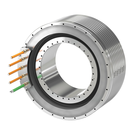
Description of the motor 1FW6 built-in torque motor Figure 2-1 1FW6 built-in torque motors with cooling jacket (left) and with integrated cooling (right) 1FW6 Built-in torque motors Configuration Manual, 07/2017, 6SN1197-0AE00-0BP9... -
Page 26: Highlights And Benefits
Highlights and benefits 2.1.1 Overview Built-in SIMOTICS T-1FW6 torque motors are designed as built-in motors for use in low- speed direct drives with a high torque output. These built-in torque motors are liquid-cooled, permanent-magnet-excited, high-pole-number three-phase synchronous motors with hollow-shaft rotors. The motors are delivered as components that are subsequently built-in. -
Page 27: Benefits
To ensure that the motor and the encoder are optimally integrated into the mechanical structure, Siemens offers its Mechatronic Support service, see Catalog. For additional information, please contact your Siemens contact person, also refer to the Internet link in the Introduction under "Technical Support". -
Page 28: Use For The Intended Purpose
Where relevant, take into account deviations regarding approvals or country-specific regulations. • Contact your local Siemens office if you have any questions relating to correct use. • If you wish to use special versions and design versions whose technical details vary from the motors described in this document, then you must contact your local Siemens office. - Page 29 Description of the motor 2.2 Use for the intended purpose In conjunction with the SINAMICS S120 drive system, the built-in torque motors can be used as a direct drive for the following machine applications, for example: ● Rotary axes ● Rotary tables, rotary indexing machines, sub-machine assemblies ●...
-
Page 30: Technical Features And Ambient Conditions
Description of the motor 2.3 Technical features and ambient conditions Technical features and ambient conditions 2.3.1 Directives and standards Standards that are complied with SIMOTICS S, SIMOTICS M, SIMOTICS L, SIMOTICS T, SIMOTICS A motors – subsequently called the "SIMOTICS motor series " – comply with the following standards: ●... -
Page 31: Danger From Strong Magnetic Fields
Quality systems Siemens AG employs a quality management system that meets the requirements of ISO 9001 and ISO 14001. Certificates for SIMOTICS motors can be downloaded from the Internet at the following link: Certificates for SIMOTICS motors (https://support.industry.siemens.com/cs/ww/de/ps/13347/cert) - Page 32 Description of the motor 2.3 Technical features and ambient conditions Components with permanent magnets The rotors of the 1FW6 built-in torque motors described in this manual contain permanent magnets. Figure 2-2 Schematic representation of the static magnetic field of a rotor, as a function of distance Risk to persons as a result of strong magnetic fields WARNING Risk of death as a result of permanent magnet fields...
- Page 33 Description of the motor 2.3 Technical features and ambient conditions For magnetic fields, you must carefully comply with the requirements laid down in the DGUV regulation 103-013 of the German Social Accident Insurance. CAUTION Safety distance to the rotor The rotor magnetic fields are permanent. If you come into direct bodily contact with the rotors, a static magnetic flux density of 2 T is not exceeded.
- Page 34 Description of the motor 2.3 Technical features and ambient conditions WARNING Risk of rotor permanent magnets causing crushing injuries The forces of attraction of magnetic rotors act on materials that can be magnetized. The forces of attraction increase significantly close to the rotor. The response threshold of 3 mT for risk of injury through attraction and causing a projectile effect is reached at a distance of 100 mm (Directive 2013/35/EU).
- Page 35 Description of the motor 2.3 Technical features and ambient conditions First aid in the case of accidents involving permanent magnets ● Stay calm. ● Press the emergency stop switch and, where necessary, switch off the main switch if the machine is live. ●...
-
Page 36: Technical Features
Description of the motor 2.3 Technical features and ambient conditions 2.3.3 Technical features Note The values specified in the following table only apply in conjunction with the system prerequisites described in "System integration". Table 2- 1 Standard version of the 1FW6 built-in torque motor Technical feature Version Motor type... - Page 37 Description of the motor 2.3 Technical features and ambient conditions Technical feature Version Insulating material class of stator Temperature class 155 (F) winding according to EN 60034-1 Impulse withstand voltage IVIC: C insulation class according to EN 60034-18-41 (IEC 60034-18-41) Magnet material Rare earth material Connection, electrical...
-
Page 38: Defining The Direction Of Rotation
Description of the motor 2.3 Technical features and ambient conditions 2.3.4 Defining the direction of rotation Direction of rotation If the built-in torque motor is connected with a phase sequence U-V-W, and is fed from a three-phase system with a clockwise phase sequence, then the rotor rotates clockwise. You can identify the direction of rotation by viewing the DE of the built-in torque motor. - Page 39 Description of the motor 2.3 Technical features and ambient conditions Table 2- 2 Ambient conditions are based on climate class 3K3 Ambient parameter Unit Value Low air temperature °C High air temperature °C + 40 Low relative humidity High relative humidity Low absolute humidity High absolute humidity Rate of temperature change...
-
Page 40: Scope Of Delivery
Description of the motor 2.3 Technical features and ambient conditions 2.3.6 Scope of delivery 2.3.6.1 Built-in torque motor with a cooling jacket ● The rotor is secured in the stator by means of transport locks and is protected using a spacer film ●... -
Page 41: Derating Factors
Description of the motor 2.4 Derating factors Table 2- 4 Prohibit signs provided according to BGV A8 and EN ISO 7010 and their significance Sign Meaning Sign Meaning No access for No access for persons with persons with pacemakers metal implants or implanted (P014) defibrillators... -
Page 42: Selection And Ordering Data
Description of the motor 2.5 Selection and ordering data Selection and ordering data 2.5.1 Order designation The article number serves as order designation. The article number (MLFB) comprises a combination of digits and letters. When placing an order, it is sufficient just to specify the unique Article number. -
Page 43: Standard 1Fw6 Built-In Torque Motor
Description of the motor 2.5 Selection and ordering data 2.5.1.1 Standard 1FW6 built-in torque motor 1FW6 Built-in torque motors Configuration Manual, 07/2017, 6SN1197-0AE00-0BP9... -
Page 44: Stator As Individual Component
Description of the motor 2.5 Selection and ordering data 2.5.1.2 Stator as individual component 1FW6 Built-in torque motors Configuration Manual, 07/2017, 6SN1197-0AE00-0BP9... -
Page 45: Rotor As Individual Component
Description of the motor 2.5 Selection and ordering data 2.5.1.3 Rotor as individual component Note IATA regulations must be complied with when transporting rotors by air. 2.5.1.4 Ordering notes You can order a complete built-in torque motor (stator, rotor with transport locks) using a single order designation (article number). -
Page 46: Ordering Examples
Description of the motor 2.5 Selection and ordering data 2.5.1.5 Ordering examples Example 1: Stator and rotor preassembled with transportation locks; cooling jacket; axial cable outlet for SINAMICS S120 drive system, Motor Modules 18 A / 36 A: Article number 1FW6090–0PB15–1JC2 Example 2: Stator and rotor preassembled with transportation locks;... - Page 47 Description of the motor 2.5 Selection and ordering data Table 2- 6 Built-in torque motors: overview (part 1 of 2) Order desig. / Rated torque Max. torque Rated cur- Max. current Rated speed Max. speed at rent max. torque Size MAX,MMAX in Nm in Nm...
- Page 48 Description of the motor 2.5 Selection and ordering data Order desig. / Rated torque Max. torque Rated cur- Max. current Rated speed Max. speed at rent max. torque Size MAX,MMAX in Nm in Nm in A in A in rpm in rpm 1FW6150-xxB07-4Fxx 38.7...
- Page 49 Description of the motor 2.5 Selection and ordering data Order desig. / Rated torque Max. torque Rated cur- Max. current Rated speed Max. speed at rent max. torque Size MAX,MMAX in Nm in Nm in A in A in rpm in rpm 1FW6190-xxB10-8Fxx 1140...
- Page 50 Description of the motor 2.5 Selection and ordering data Order desig. / Rated torque Max. torque Rated cur- Max. current Rated speed Max. speed at rent max. torque Size MAX,MMAX in Nm in Nm in A in A in rpm in rpm 1FW6290-xxB11-2Pxx 3110...
- Page 51 Description of the motor 2.5 Selection and ordering data Order desig. / size Rated power External diameter Internal diameter Length of Motor Moment of inertia loss of stators of rotors stator mass of rotor J in kW in mm in mm in mm in kg in 10...
- Page 52 Description of the motor 2.5 Selection and ordering data Order desig. / size Rated power External diameter Internal diameter Length of Motor Moment of inertia loss of stators of rotors stator mass of rotor J in kW in mm in mm in mm in kg in 10...
- Page 53 Description of the motor 2.5 Selection and ordering data Order desig. / size Rated power External diameter Internal diameter Length of Motor Moment of inertia loss of stators of rotors stator mass of rotor J in kW in mm in mm in mm in kg in 10...
-
Page 54: Rating Plate Data
Description of the motor 2.6 Rating plate data Rating plate data Technical data of the stator is provided on the rating plate (name plate). A second rating plate is provided loose for the stator. If, at a certain point in time, the stator and rotor are separated, then you must ensure that the stator and rotor can be assigned to one another at a later point in time. -
Page 55: Mechanical Properties
Mechanical properties Cooling A water-cooling system dissipates the heat loss generated by the stator winding. ● Connect the cooling ducts to the cooling circuit of a cooling device. You can find the characteristic curves for the pressure drop of the cooling medium between the inlet and return circuit of the cooling system as a function of the volume flow rate in Chapter "Technical data and characteristics". -
Page 56: Cooling Circuits
Mechanical properties 3.1 Cooling 3.1.1 Cooling circuits Cooling circuit requirements Avoid algae growth by using suitable chemical agents and opaque water lines. We recommend that the cooling circuits be designed as closed systems. The maximum permissible pressure is 10 bar. NOTICE Blocked and clogged cooling circuits Cooling circuits can become blocked and clogged as a result of pollution and longer-term... - Page 57 Mechanical properties 3.1 Cooling Materials used in the cooling circuits of torque motors Table 3- 1 Materials in the cooling circuits of torque motors (not including the material used for the connections) Cooling jacket Integrated cooling (main Integrated cooling (precision Cooling connection adapter cooler) for cooler) for...
- Page 58 Mechanical properties 3.1 Cooling Calculating the thermal power that can be dissipated by the cooler Average density of the coolant: ρ kg/m Average specific heat capacity of the coolant: J/(kg K) Temperature deviation vis-à-vis the intake temperature: ΔT Volume flow: Coolant inlet temperature NOTICE Corrosion in the machine...
- Page 59 Mechanical properties 3.1 Cooling The following diagram shows the principle dependency of the relevant continuous motor current on the intake temperature of the cooling water in the main cooler The rotor losses are omitted as negligible. Figure 3-1 Influence of the coolant inlet temperature Heat-exchanger unit Use a heat-exchanger unit to ensure an inlet temperature of 35 °C.
-
Page 60: Coolant
Power derating when using oil as coolant If you are using oil as coolant, then this can reduce the power loss dissipated by the cooler. Appropriately reduce the motor power. Please contact your local Siemens office if you have any questions. - Page 61 Mechanical properties 3.1 Cooling General requirements placed on the cooling medium The cooling medium must be pre-cleaned or filtered in order to prevent the cooling circuit from becoming blocked. The formation of ice is not permitted! Note The maximum permissible size for particles in the cooling medium is 100 μm. Requirements placed on the water Water which is used as basis for the coolant must comply as a minimum with the following requirements:...
-
Page 62: Degree Of Protection
Mechanical properties 3.2 Degree of protection Degree of protection NOTICE Damage to the motor caused by pollution If the area where the motor is installed is polluted and dirty, then the motor can malfunction and clog up. • Keep the area where the motor is installed free of all dirt and pollution. The machine construction surrounding the motor must fulfill degree of protection IP54 to EN 60529 as a minimum. -
Page 63: Noise Emission
Mechanical properties 3.4 Noise emission Noise emission The following components and settings influence the noise levels reached when built-in motors are operational: ● Machine design ● Encoder system ● Storage ● Controller settings ● Pulse frequency As a result of unfavorable machine designs, configuration or system settings, measuring surface sound pressure levels of over 70dB (A) can occur. - Page 64 Mechanical properties 3.5 Service and inspection intervals WARNING Risk of death and crushing as a result of permanent magnet fields Severe injury and material damage can result if you do not take into consideration the safety instructions relating to permanent magnet fields. •...
- Page 65 Mechanical properties 3.5 Service and inspection intervals WARNING Risk of burning when touching hot surfaces There is a risk of burning when touching hot surfaces immediately after the motor has been operational. • Wait until the motor has cooled down. WARNING Danger to life when the cooling system bursts The motor will overheat if it is operated without cooling.
- Page 66 Mechanical properties 3.5 Service and inspection intervals WARNING Electrical shock hazard Every movement of the rotor compared with the stator and vice versa induces a voltage at the stator power connections. When the motor is switched on, the stator power connections are also at a specific voltage. If you use defective cable ports, you could suffer an electric shock.
- Page 67 • When carrying out disassembly work, observe the information in Chapter "Decommissioning and disposal " in the operating instructions "SIMOTICS T-1FW6 built- in motors." The motors have been designed for a long service life. Carefully ensure that maintenance work is correctly performed, e.g.
- Page 68 Siemens regarding personal injury or material damage. Siemens service centers are available to answer any questions you may have. Siemens Service Center addresses can be found at http://www.siemens.com/automation/service&support...
-
Page 69: Maintenance Work
Mechanical properties 3.5 Service and inspection intervals 3.5.2 Maintenance work Performing maintenance work on the motor Note It is essential that you observe the safety information provided in this documentation. As a result of their inherent principle of operation, the motors are always wear-free. To ensure that the motor functions properly and remains free of wear, the following maintenance work needs to be carried out: ●... -
Page 70: Checking The Insulation Resistance
• If a higher DC or AC voltage is necessary to test the machine/plant, you must coordinate the test with your local Siemens office! • Carefully observe the operating instructions of the test equipment! Always proceed as follows when testing the insulation resistance of individual motors: 1. -
Page 71: The Inspection And Change Intervals For The Coolant
Mechanical properties 3.5 Service and inspection intervals 3.5.4 The inspection and change intervals for the coolant Test and replacement intervals of the cooling medium The test and replacement intervals for the cooling medium should be agreed with the manufacturers of the anti-corrosion agent and the cooling system. 1FW6 Built-in torque motors Configuration Manual, 07/2017, 6SN1197-0AE00-0BP9... - Page 72 Mechanical properties 3.5 Service and inspection intervals 1FW6 Built-in torque motors Configuration Manual, 07/2017, 6SN1197-0AE00-0BP9...
-
Page 73: Motor Components And Options
Motor components and options Motor components 4.1.1 Overview of the motor construction The built-in torque motor contains the following components: ● Stator: this comprises an iron core and a 3-phase winding. The winding is encapsulated to ensure that the heat loss can be dissipated more effectively. -
Page 74: Motors With Integrated Cooling
Motor components and options 4.1 Motor components Figure 4-1 Motor components of the 1FW609 and 1FW613 built-in torque motors with cooling jacket 4.1.1.2 Motors with integrated cooling Motors with integrated single-circuit cooling These motors have an integrated single-circuit cooling system that is ready to be connected. Further, they are compact, and can therefore be simply integrated into a machine. - Page 75 Motor components and options 4.1 Motor components Motors with integrated dual-circuit cooling These motors are equipped with a ready-to-connect, integrated dual-circuit cooling system, which provides considerable thermal insulation with respect to the mechanical axis construction. The dual-circuit cooling system comprises a main and precision cooler (thermo-sandwich®...
-
Page 76: Cooling Method
Motor components and options 4.1 Motor components 4.1.1.3 Cooling method The stator in the built-in torque motors is equipped with a liquid cooler for dissipating heat loss. The cooling method used depends on the size (external diameter) of the motor as follows. Table 4- 1 Cooling method Size... - Page 77 Motor components and options 4.1 Motor components Temp-S All motors are equipped with the following temperature monitoring circuit to protect the motor winding against thermal overload: ● 1 x PTC 130 °C temperature sensor per phase winding U, V and W, i.e. response threshold at 130 °C In addition, 1FW6090-xxxxx-xxx2 to 1FW6290-xxxxx-xxx2 motors are equipped with the following temperature monitoring circuit:...
- Page 78 Motor components and options 4.1 Motor components Table 4- 2 Types of temperature monitoring circuits Article No. Temp-S (PTC 130 °C), Temp-S (PTC 130 °C), Temp-S (PTC 130 °C and PTC 150 °C), Temp-F (KTY 84) Temp-F (Pt1000) Temp-F (KTY 84) 1FW6050-xxxxx-xxx1 1FW6050-xxxxx-xxx3 1FW6060-xxxxx-xxx1...
- Page 79 Motor components and options 4.1 Motor components NOTICE Motor destroyed as a result of overtemperature The motor can be destroyed if the motor winding overheats. • Connect Temp-S. • Evaluate Temp-S. • Ensure that the shutdown time is not exceeded. Note No temperature monitoring with Temp-S As a result of their non-linear characteristic, PTC temperature sensors are not suitable for...
-
Page 80: Technical Features Of Temperature Sensors
Motor components and options 4.1 Motor components No direct connection of the temperature monitoring circuits WARNING Risk of electric shock when incorrectly connecting the temperature monitoring circuit In the case of a fault, circuits Temp-S and Temp-F do not provide safe electrical separation with respect to the power components. - Page 81 Motor components and options 4.1 Motor components Table 4- 3 Technical data of the PTC temperature sensors Name Description Type PTC triplet acc. to DIN 44082 Individual PTC temperature sensor according to DIN 44081 Response threshold 150 °C ± 5 K (nominal response temperature ϑ...
- Page 82 Motor components and options 4.1 Motor components Technical features of the KTY 84 temperature sensor The KTY 84 has a progressive temperature resistance characteristic that is approximately linear. In addition, the KTY 84 has a low thermal capacity and provides good thermal contact with the motor winding.
- Page 83 Motor components and options 4.1 Motor components Technical features of the Pt1000 temperature sensor The Pt1000 has a linear temperature resistance characteristic. In addition, the Pt1000 has a low thermal capacity and provides good thermal contact with the motor winding. Table 4- 5 Technical data of the Pt1000 PTC thermistor Name...
-
Page 84: Encoders
When designing, constructing and optimizing your machine, we can support you with measurement-based and computer-based analyses. You can obtain additional information from your Siemens contact person, also refer to the Internet link in the introduction under "Technical Support". Encoder system In the following text, encoder systems stand for angular measuring systems, rotary encoders, encoders etc. - Page 85 Motor components and options 4.1 Motor components Requirements regarding the encoder Your choice of encoder essentially depends on the following application and converter- specific conditions: ● required maximum speed ● required speed accuracy ● required angular precision and resolution ● pollution level expected ●...
- Page 86 4.1 Motor components Figure 4-5 Performance-resolution diagram Note We cannot guarantee the composition, nature, state, or quality of non-Siemens products. Read the detailed text in "Manufacturer recommendations" in the appendix. Note General mechanical conditions Take into account the permissible mechanical speed, limit frequency of the encoder and Control Unit.
- Page 87 To ensure that the encoder is optimally integrated into the mechanical system, Siemens offers its Mechatronic Support service, see Catalog. For additional information, please contact your local Siemens office. You can find the "Technical Support" Internet link in Chapter "Introduction".
- Page 88 Motor components and options 4.1 Motor components Figure 4-6 Mounting diagram (example) Note Additional mounting examples are provided in Chapter "Installation examples (Page 146)". 1FW6 Built-in torque motors Configuration Manual, 07/2017, 6SN1197-0AE00-0BP9...
-
Page 89: Bearings
Motor components and options 4.1 Motor components 4.1.4 Bearings Selecting the bearing 1FW6 torque motors are built-in motors for directly driven rotary or swivel axes. To set up a complete drive unit, a bearing between the stator and rotor is required in addition to the phase-angle encoder system. -
Page 90: Braking Concepts
Motor components and options 4.1 Motor components 4.1.5 Braking concepts WARNING Uncontrolled coast down of the drive as a result of malfunctions Malfunctions on a rotating machine axes can lead to the drive coasting to a stop in an uncontrolled manner. •... - Page 91 Motor components and options 4.1 Motor components Braking and emergency stop concepts In the case of rotating axes that are restricted to a rotation angle of < 360°, damping and impact absorption elements at the limits of the rotation range offer reliable protection. To dissipate the kinetic energy of the rotating mass before it comes into contact with the damping elements, the following measures should be taken to support mechanical braking systems:...
- Page 92 Motor components and options 4.2 Options Deploying a holding brake Due to cogging torques, torque motors can be pulled into a preferable magnetic operating position if the motor is no longer supplied with power from the drive. If the drive is already at a standstill, this can cause unexpected movements in up to a half magnetic pole pitch in both directions.
-
Page 93: Options
Motor components and options 4.2 Options Options 4.2.1 Round sealing ring (O ring) 4.2.2 Cooling connection adapter Note The cooling connection adapter is an option, and only fits for built-torque motors with integrated cooling, for frame sizes 16, 19, 23 and 29. Please order when required. 1FW6 Built-in torque motors Configuration Manual, 07/2017, 6SN1197-0AE00-0BP9... -
Page 94: Plug Connector
Motor components and options 4.2 Options 4.2.3 Plug connector Connector type Connector size Article No. Power connection 6FX2003-0LA10 Power connection 6FX2003-0LA00 Signal connection 6FX2003-0SU07 1FW6 Built-in torque motors Configuration Manual, 07/2017, 6SN1197-0AE00-0BP9... -
Page 95: Configuration
When designing, constructing and optimizing your machine, we can support you with measurement-based and computer-based analyses. You can obtain additional information from your Siemens contact person, also refer to the Internet link in the introduction under "Technical Support". Configuring software 5.1.1... -
Page 96: Starter Drive/Commissioning Software
● Comments on system reactions ● Installation information of the drive and control components ● Energy considerations of the configured drive systems You can find additional information that you can download in the Internet at SIZER (https://support.industry.siemens.com/cs/document/54992004/sizer-for-siemens- drives?dti=0&pnid=13434&lc=en-WW). 5.1.2 STARTER drive/commissioning software... - Page 97 Configuration 5.2 Configuring workflow Procedure Selecting the motors is generally an iterative process because – in particular with highly- dynamic direct drives – the moment of inertia of the motor type is a factor in determining the required torques. 1FW6 Built-in torque motors Configuration Manual, 07/2017, 6SN1197-0AE00-0BP9...
-
Page 98: General Mechanical Conditions
Configuration 5.2 Configuring workflow 5.2.1 General mechanical conditions Moment of inertia The kinetic energy generated by a rotating body is directly proportional to its moment of inertia J in kgm . The moment of inertia takes into account the rotating mass and its spatial distribution across the entire volume of the body with respect to the rotary axes. -
Page 99: Type Of Load Cycle
Configuration 5.2 Configuring workflow 5.2.2 Type of load cycle Uninterrupted duty S1 With uninterrupted duty S1, the motor runs permanently with a constant load. The load period is sufficient to achieve thermal equilibrium. The rated data is of relevance when dimensioning the motor for uninterrupted duty. NOTICE Motor overload An excessively high load can lead to shutdown, or if the temperature sensors are not... - Page 100 Configuration 5.2 Configuring workflow Example A motor should be operated with maximum current from the cold state. ● I = 47 A, I = 26 A; this results in ν = 3.268 ● t = 180 s The motor can be operated for a maximum of 66 s at maximum current. Intermittent duty S3 With intermittent duty S3, periods of load time Δt with constant current alternate with...
- Page 101 , it is not permissible that the rms current exceeds the rated current: In this respect, the cycle duration should not exceed 10% of the thermal time constant t If a longer cycle duration is necessary, please contact your local Siemens office. Example...
-
Page 102: Torque-Time Diagram
Configuration 5.2 Configuring workflow Example Figure 5-2 Example of a duty cycle with a speed-time diagram n(t), the resulting angular acceleration-time diagram α(t), and a machining torque-time diagram M 5.2.3 Torque-time diagram Required motor torque The required motor torque M is always the sum of the individual torques. - Page 103 Configuration 5.2 Configuring workflow Determining the required motor torque The frictional torque characteristic can be determined on the basis of the speed characteristic. The total formula can then be used to create the motor torque-time diagram (see diagram below) from which the required peak torque M can be read directly.
- Page 104 Configuration 5.2 Configuring workflow In addition to the peak torque M , the required rms torque M of the motor is also a mMAX decisive factor when dimensioning the motor. The rms torque M mainly responsible for the temperature rise in the motor can be derived from the motor torque-time diagram by means of quadratic averaging (root mean square) and must not exceed the rated torque M If the individual torques are stable in each section, the integral can be simplified to create a totals formula (see also the following diagram).
-
Page 105: Selecting Motors
70 % of its rated torque, see also M * in Chapter "Technical data and characteristics". For exact configurations, contact your local Siemens office. Note Uneven current load Not all of the three phases are necessarily evenly loaded in all motor operating modes! Examples of uneven current load: •... -
Page 106: Motor Torque-Speed Diagram
Configuration 5.2 Configuring workflow 5.2.6 Motor torque-speed diagram Checking torques and speeds At high speeds, the maximum available motor torque is limited by the available DC link voltage. The speeds occurring in the motion sequence can exceed the maximum speed n MAX,MMAX specified for the motor type at the maximum torque M . - Page 107 Configuration 5.2 Configuring workflow Determining the motor torque-speed diagram If the motor torque-speed diagram is not available, then determine the motor torque-speed diagram from the following data taken from the "Motor torque speed diagram" figure. ● Maximum torque M with the associated speed n MAX,MMAX ●...
-
Page 108: Torque-Speed Requirements
Configuration 5.2 Configuring workflow 5.2.7 Torque-speed requirements Fulfilling the torque-speed requirements If the selected torque motor cannot fulfill the torque-speed requirements, the following options are available: ● Larger motor If an operating point in the range A is required, a motor with a larger diameter and/or longer length is required (see motor 2 in the following diagram). -
Page 109: Checking The Moments Of Inertia
Configuration 5.2 Configuring workflow ● Field weakening operation If an operating point in range C is required, then the motor must be operated in the field weakening range (see the following diagram). Advantage: Significantly higher speeds are possible. Disadvantage: The torques available are very low. A lower current is required, refer to the description for field weakening operation in Chapter "Technical data and characteristics"... -
Page 110: Selecting The Drive System Components For The Power Connection
• To dampen the oscillations we recommend the use of the associated Active Interface Module or an HFD reactor with damping resistor. For specific details, refer to the documentation of the drive system being used or contact your local Siemens office. Note The corresponding Active Interface Module or the appropriate HFD line reactor must be used to operate the Active Line Module controlled infeed unit. -
Page 111: Calculation Of The Required Infeed
Configuration 5.2 Configuring workflow 5.2.10 Calculation of the required infeed Dimensioning the Active Infeed Use the drive's power balance to dimension the Active Infeed. The first important quantity to know is the mechanical power P to be produced on the mech motor shaft. -
Page 112: Examples
Configuration 5.3 Examples Examples Note The data used here may deviate from the values specified in "Technical data and characteristics". This does not affect the configuration procedure, however. General conditions for positioning within a defined period ● Moment of inertia in kgm : J = 5.1 kg m moved cylindrical mass m = 30 kg with equivalent radius r = 0.583 m;... - Page 113 Configuration 5.3 Examples The following must be determined: ● Suitable torque motor ● Angular velocity ω in rad/s or speed n in rpm ● Angular acceleration α in rad/s The shape of the traversing profile is not stipulated, but the angle to be traversed and the duration are specified for this.
- Page 114 Configuration 5.3 Examples Table 5- 2 Functions of the individual sections in the traversing profile Section I Section II α (t) = α α (t) = - α ω (t) = α t ω (t) = - α t + α t φ...
- Page 115 Configuration 5.3 Examples The following applies for the required acceleration torque: = (J + J ) • α Since the moment of inertia J for the 1FW6 motor is not known at the time of configuring, then initially J = 0 kgm must be assumed.
- Page 116 Configuration 5.4 Installation Evaluation Both motors are suitable for this positioning task. The installation requirements govern which motor is better suited. During positioning, the motor reaches a torque that far exceeds its rated torque M , and the resulting power loss is much greater than the permissible continuous power loss.
-
Page 117: Installation
Configuration 5.4 Installation Installation 5.4.1 Safety instructions for mounting WARNING Risk of death and crushing as a result of permanent magnet fields Severe injury and material damage can result if you do not take into consideration the safety instructions relating to permanent magnet fields. •... - Page 118 Configuration 5.4 Installation WARNING Risk of rotor permanent magnets causing crushing injuries The forces of attraction of magnetic rotors act on materials that can be magnetized. The forces of attraction increase significantly close to the rotor. The response threshold of 3 mT for risk of injury through attraction and causing a projectile effect is reached at a distance of 100 mm (Directive 2013/35/EU).
- Page 119 Configuration 5.4 Installation NOTICE Destruction of the motor If you fix the rotor and/or stator at both ends, this can result in significant material deformation in the machine assembly due to thermal expansion, which could destroy the motor. • The machine must be designed in such a way that both the rotor and the stator are each secured on one side only.
- Page 120 Configuration 5.4 Installation WARNING Electric shock caused by defective cables Defective connecting cables can cause an electric shock and/or material damage, e.g. by fire. • When installing the motor, make sure that the connection cables – are not damaged – are not under tension –...
-
Page 121: Forces That Occur Between The Stator And Rotor
Configuration 5.4 Installation CAUTION Risk of crushing when the rotor is installed There is a risk of crushing when the rotor of an installed torque motor rotates! • Wear safety gloves. • Take extreme care when performing any work. CAUTION Sharp edges and falling objects Sharp edges can cause cuts and falling objects can injure feet. - Page 122 Configuration 5.4 Installation Radial forces between the stator and rotor The following table shows the active radial forces (in N per 0.1 mm centering error) between the stator and rotor. The longer the active component, the greater the radial force. Table 5- 3 Radial forces in N/0.1 mm with radial centering errors during installation Active length in mm...
-
Page 123: Installation Device
Configuration 5.4 Installation Axial forces between the stator and rotor Table 5- 4 Axial forces (in N) between the stator and rotor during installation 1FW605 1FW606 1FW609 1FW613 1FW615 1FW616 1FW619 1FW623 1FW629 Axial forces in N Note At the beginning and at the end of the insertion process, the axial forces of attraction between the stator and rotor are 4x to 5x higher. - Page 124 Configuration 5.4 Installation Example: Centering and installing motors with a cooling jacket 1. Place the stator so that it is centered in the holding fixture of the lower part of the installation device. 2. Place the rotor so that it is centered in the holding fixture of the upper part of the installation device.
- Page 125 Configuration 5.4 Installation 4. Carefully lower the rotor using the upper part of the installation device and carefully fit it into the lower part of the installation device in such a way that the rotor can be aligned centrically over the sleeve bearing and shaft in the stator. WARNING Risk of crushing when the rotor is lowered.
- Page 126 Configuration 5.4 Installation 6. Fix the stator and rotor using the transport locks. To do this, tighten the bolts with the specified tightening torques according to the table "Required property classes and tightening torques for stator and rotor." 7. Remove the spacer foil. When the stator and rotor are correctly centered, the spacer film can be easily removed by hand.
-
Page 127: Specifications Relating To The Mounting Side
Configuration 5.4 Installation 5.4.4 Specifications relating to the mounting side Permissible mounting side Note As a result of the design, the following motors may only be mounted at the A flange. Table 5- 5 Mounting at the A flange 1FW616 1FW619 1FW623 1FW629... -
Page 128: Specifications For Mounting Torque Motors
Configuration 5.4 Installation 5.4.5 Specifications for mounting torque motors Mounting system The following must be taken into account when the torque motor is mounted: ● Only use new (unused) fixing screws. ● The mounting surfaces must be free of oil and grease. ●... - Page 129 Configuration 5.4 Installation Screw material and tightening torques Screws of varying strength classes are required to secure the motor to the machine structure. The table below shows the required strength classes and tightening torques for the stator and rotor fixing screws. Table 5- 6 Required strength classes and tightening torques for the stator and rotor Motor...
-
Page 130: Procedure When Installing The Motor
Configuration 5.4 Installation Table 5- 7 Maximum permissible screw insertion depths for the stator and rotor Component Max. permissible screw-in depth Thread in mm 1FW605, 1FW606 / stator 8.5 + section without thread *) 1FW605, 1FW606 / rotor 1FW609, 1FW613 / stator and rotor 1FW615 / stator and rotor 1FW616, 1FW619, 1FW623 / stator 1FW616, 1FW619, 1FW623 / rotor... - Page 131 Configuration 5.4 Installation 1. Preparing and cleaning the mounting surfaces for motor parts and the machine. – Deburr and round off the holes (e.g. cooling inlet/outlet holes) inside the machine housing. – Carefully remove any machining residue (e.g. chippings, dirt, foreign bodies, etc.). –...
-
Page 132: Cooler Connection
Configuration 5.4 Installation 7. Completely remove any transport locks that are still in place. This point is not applicable for stator and rotor as individual components. 8. Remove the spacer film. When the stator and rotor are correctly centered, the spacer film can be easily removed by hand. - Page 133 Configuration 5.4 Installation Figure 5-14 Cooler connection for 1FW609 and 1FW613 (example) Figure 5-15 Cooler connection for 1FW615 (example) 1FW6 Built-in torque motors Configuration Manual, 07/2017, 6SN1197-0AE00-0BP9...
-
Page 134: Cooler Connection For Motors With Integrated Cooling
• Do not remove the cooling connection plate. Note It is only permissible to remove the locking plate for the cooling connection for 1FW605 and 1FW606 motors for service purposes, and this must be done by a Siemens service center employee. 1FW6 Built-in torque motors... - Page 135 Configuration 5.4 Installation Cooling connection adapter (option) Figure 5-16 Cooling connection adapter (option) for parallel connection of main cooler and precision cooler for 1FW616, 1FW619, 1FW623, 1FW629 1FW6 Built-in torque motors Configuration Manual, 07/2017, 6SN1197-0AE00-0BP9...
- Page 136 Configuration 5.4 Installation Cooler connection for 1FW605 and 1FW606 Figure 5-17 Axial cooler connection 1FW605 and 1FW606 Note Manufacturer's recommendations for plug-in connections for the coolant connection are provided in the Appendix. 1FW6 Built-in torque motors Configuration Manual, 07/2017, 6SN1197-0AE00-0BP9...
- Page 137 Configuration 5.4 Installation Cooler connection for 1FW616, 1FW619 and 1FW623 Figure 5-18 Cooling connection plate for 1FW616, 1FW619, 1FW623 Figure 5-19 Axial cooler connection with cooling connection adapter (option) for 1FW616, 1FW619, 1FW623 1FW6 Built-in torque motors Configuration Manual, 07/2017, 6SN1197-0AE00-0BP9...
- Page 138 Configuration 5.4 Installation Figure 5-20 Outer radial cooler connection with cooling connection adapter (option) for 1FW616, 1FW619, 1FW623 1FW6 Built-in torque motors Configuration Manual, 07/2017, 6SN1197-0AE00-0BP9...
- Page 139 Configuration 5.4 Installation Figure 5-21 Cooling connection adapter (option) for 1FW616, 1FW619, 1FW623 1FW6 Built-in torque motors Configuration Manual, 07/2017, 6SN1197-0AE00-0BP9...
- Page 140 Configuration 5.4 Installation Cooler connection for 1FW629 Figure 5-22 Cooling connection plate for 1FW629 1FW6 Built-in torque motors Configuration Manual, 07/2017, 6SN1197-0AE00-0BP9...
- Page 141 Configuration 5.4 Installation Figure 5-23 Axial cooler connection with cooling connection adapter (option) for 1FW629 1FW6 Built-in torque motors Configuration Manual, 07/2017, 6SN1197-0AE00-0BP9...
- Page 142 Configuration 5.4 Installation Figure 5-24 Outer radial cooler connection with cooling connection adapter (option) for 1FW629 1FW6 Built-in torque motors Configuration Manual, 07/2017, 6SN1197-0AE00-0BP9...
- Page 143 Configuration 5.4 Installation Figure 5-25 Cooling connection adapter (option) for 1FW629 1FW6 Built-in torque motors Configuration Manual, 07/2017, 6SN1197-0AE00-0BP9...
-
Page 144: Hoses For The Cooling System
For a list of companies from whom you can obtain connectors and accessories for cooling systems, see the appendix. Note We cannot guarantee the composition, nature, state, or quality of non-Siemens products. Read the detailed text in "Manufacturer recommendations" in the appendix. 5.4.7.4... - Page 145 Configuration 5.4 Installation Figure 5-26 Mounting the cooling connection adapter 1FW616, 1FW619, 1FW623 1FW6 Built-in torque motors Configuration Manual, 07/2017, 6SN1197-0AE00-0BP9...
- Page 146 Configuration 5.4 Installation Figure 5-27 Mounting the cooling connection adapter 1FW629 1FW6 Built-in torque motors Configuration Manual, 07/2017, 6SN1197-0AE00-0BP9...
-
Page 147: Checking The Work Performed
Configuration 5.4 Installation 5.4.8 Checking the work performed Checking the mounting work After installation has been completed, check that the rotor can freely rotate. Before moving the rotor, remove all tools and objects from the area of the rotor and air gap. WARNING Risk of electric shock A voltage is induced in the stator when the rotor rotates. -
Page 148: Installation Examples
Configuration 5.4 Installation 5.4.9 Installation examples Note The examples provided below are not necessarily complete nor are they suitable for all applications. Note that the rotor and stator are secured on one side on the machine construction. Depending on the machine construction, the stator can be secured on the same side as the rotor or on the opposite side. - Page 149 Configuration 5.4 Installation Image title Description Part-turn actuator with torque The construction shown is ideal for moderate load forces and motor with cooling jacket medium precision requirements (e.g. woodworking, packaging systems, tool changers). For roller drives, this construction is only suitable for short axes with low deflection. Roller drive with low shaft deflec- The construction shown is ideal for roller drives with high con- tion with torque motor with inte-...
- Page 150 Configuration 5.4 Installation Figure 5-28 Rotary table with torque motor with integrated cooling 1FW6 Built-in torque motors Configuration Manual, 07/2017, 6SN1197-0AE00-0BP9...
- Page 151 Configuration 5.4 Installation Figure 5-29 Rotary table with torque motor with cooling jacket 1FW6 Built-in torque motors Configuration Manual, 07/2017, 6SN1197-0AE00-0BP9...
- Page 152 Configuration 5.4 Installation Figure 5-30 Part-turn actuator with torque motor with integrated cooling 1FW6 Built-in torque motors Configuration Manual, 07/2017, 6SN1197-0AE00-0BP9...
- Page 153 Configuration 5.4 Installation Figure 5-31 Installing a torque motor with integrated cooling on the shaft extension of a part-turn actuator 1FW6 Built-in torque motors Configuration Manual, 07/2017, 6SN1197-0AE00-0BP9...
- Page 154 Configuration 5.4 Installation Figure 5-32 Part-turn actuator with torque motor with cooling jacket 1FW6 Built-in torque motors Configuration Manual, 07/2017, 6SN1197-0AE00-0BP9...
- Page 155 Configuration 5.4 Installation Figure 5-33 Roller drive with low shaft deflection with torque motor with integrated cooling 1FW6 Built-in torque motors Configuration Manual, 07/2017, 6SN1197-0AE00-0BP9...
- Page 156 Configuration 5.4 Installation 1FW6 Built-in torque motors Configuration Manual, 07/2017, 6SN1197-0AE00-0BP9...
-
Page 157: Technical Data And Characteristics
Technical data and characteristics The technical data and characteristics for the 1FW6 Built-in torque motors are specified in this Chapter. This data collection provides the motor data required for configuration and contains a number of additional data for more detailed calculations for detailed analyses and problem analyses. - Page 158 Technical data and characteristics 6.1 Explanations of the formula abbreviations Boundary conditions Converter DC link voltage (direct voltage value). Comment: For converter output voltages U , see Chapter "System integra- a max tion". Maximum intake temperature of the water cooler for the main cooler and preci- VORL sion cooler if the motor is to be utilized up to its rated torque M .
- Page 159 Technical data and characteristics 6.1 Explanations of the formula abbreviations Insert the appropriate data from the Chapter "Data sheets and diagrams" into the following formula. Conversion of the speed n from rpm to s and the power from W to kW has already been taken into account.
- Page 160 Technical data and characteristics 6.1 Explanations of the formula abbreviations Figure 6-1 Thermal time constant Number of pole pairs of the motor. Cogging torque. This is the torque generated by the interaction between the lami- nated core and permanent magnets at the air gap in stators that have been dis- connected from the power supply.
- Page 161 Technical data and characteristics 6.1 Explanations of the formula abbreviations Data for main motor cooler Maximum thermal power that is dissipated by the main cooler when the motor is H,MAX utilized up to the rated torque M and at the rated temperature T Recommended minimum volume flow rate in the main cooler to achieve the rated H,MIN torque M...
- Page 162 Technical data and characteristics 6.1 Explanations of the formula abbreviations Figure 6-3 Sample characteristic: "Pressure losses in the main cooler over volume flow rate" Data for precision motor cooler Maximum heat loss dissipated by the precision cooler when the motor is utilized up P,MAX to its rated torque M and at rated temperature T...
- Page 163 Technical data and characteristics 6.1 Explanations of the formula abbreviations Torque-speed diagram with field weakening S1 duty S1 duty with field weakening S3 duty, cycle duration should not exceed 10 % of the thermal time constant t S3 duty with field weakening, cycle duration should not exceed 10 % of the thermal time constant t Voltage limit characteristic Limit characteristic for S1 duty Voltage limit characteristic with field weakening...
- Page 164 Technical data and characteristics 6.1 Explanations of the formula abbreviations For the SINAMICS S120 drive system, as a result of the field weakening function, when the "voltage limiting characteristic" is reached, then the voltage induced in the motor winding is automatically compensated.
-
Page 165: Data Sheets And Diagrams
Technical data and characteristics 6.2 Data sheets and diagrams Short-circuit braking torque For each frame size and active part length, the short-circuit braking torque M is specified as characteristic "short-circuit braking torque with respect to speed". Figure 6-7 Short-circuit braking torque speed diagram (example) Data sheets and diagrams Table 6- 1 Color coding of the M-n characteristics in the diagrams... -
Page 166: 1Fw6050-Xxxxx-Xxxx
Technical data and characteristics 6.2 Data sheets and diagrams 6.2.1 1FW6050-xxxxx-xxxx Data sheet 1FW6050-xxB03-xxxx Table 6- 2 1FW6050-xxB03-0Fxx Technical data Symbol Unit -xxB03-0Fxx 1FW6050 Boundary conditions DC link voltage Water cooling inlet temperature °C VORL Rated temperature of winding °C Data at the rated operating point Rated torque 23.2... - Page 167 Technical data and characteristics 6.2 Data sheets and diagrams Technical data Symbol Unit -xxB03-0Fxx 1FW6050 Data for main motor cooler Maximum dissipated thermal power 0.698 H,MAX Recommended minimum volume flow l/min H,MIN Cooling medium temperature increase ΔT 3.86 Pressure drop Δp 0.133 1FW6 Built-in torque motors...
- Page 168 Technical data and characteristics 6.2 Data sheets and diagrams Characteristics for 1FW6050-xxB03-xxxx Torque M with respect to speed n Torque M with respect to speed n 1FW6 Built-in torque motors Configuration Manual, 07/2017, 6SN1197-0AE00-0BP9...
- Page 169 Technical data and characteristics 6.2 Data sheets and diagrams Short-circuit braking torque M with respect to speed n Main cooler - pressure losses Δ p with respect to the volume flow 1FW6 Built-in torque motors Configuration Manual, 07/2017, 6SN1197-0AE00-0BP9...
- Page 170 Technical data and characteristics 6.2 Data sheets and diagrams Rotor power loss P with respect to speed n 1FW6 Built-in torque motors Configuration Manual, 07/2017, 6SN1197-0AE00-0BP9...
- Page 171 Technical data and characteristics 6.2 Data sheets and diagrams Data sheet 1FW6050-xxB05-xxxx Table 6- 3 1FW6050-xxB05-0Fxx Technical data Symbol Unit -xxB05-0Fxx 1FW6050 Boundary conditions DC link voltage Water cooling inlet temperature °C VORL Rated temperature of winding °C Data at the rated operating point Rated torque 39.5 Rated current...
- Page 172 Technical data and characteristics 6.2 Data sheets and diagrams Technical data Symbol Unit -xxB05-0Fxx 1FW6050 Data for main motor cooler Maximum dissipated thermal power 0.941 H,MAX Recommended minimum volume flow l/min 3.22 H,MIN Cooling medium temperature increase ΔT Pressure drop Δp 1FW6 Built-in torque motors Configuration Manual, 07/2017, 6SN1197-0AE00-0BP9...
- Page 173 Technical data and characteristics 6.2 Data sheets and diagrams Characteristics for 1FW6050-xxB05-xxxx Torque M with respect to speed n Torque M with respect to speed n 1FW6 Built-in torque motors Configuration Manual, 07/2017, 6SN1197-0AE00-0BP9...
- Page 174 Technical data and characteristics 6.2 Data sheets and diagrams Short-circuit braking torque M with respect to speed n Main cooler - pressure losses Δ p with respect to the volume flow 1FW6 Built-in torque motors Configuration Manual, 07/2017, 6SN1197-0AE00-0BP9...
- Page 175 Technical data and characteristics 6.2 Data sheets and diagrams Rotor power loss P with respect to speed n 1FW6 Built-in torque motors Configuration Manual, 07/2017, 6SN1197-0AE00-0BP9...
- Page 176 Technical data and characteristics 6.2 Data sheets and diagrams Data sheet 1FW6050-xxB07-xxxx Table 6- 4 1FW6050-xxB07-0Fxx, 1FW6050-xxB07-0Kxx Technical data Symbol Unit -xxB07-0Fxx -xxB07-0Kxx 1FW6050 Boundary conditions DC link voltage Water cooling inlet temperature °C VORL Rated temperature of winding °C Data at the rated operating point Rated torque 55.7...
- Page 177 Technical data and characteristics 6.2 Data sheets and diagrams Technical data Symbol Unit -xxB07-0Fxx -xxB07-0Kxx 1FW6050 Data for main motor cooler Maximum dissipated thermal power 1.15 1.12 H,MAX Recommended minimum volume flow l/min 3.83 3.83 H,MIN Cooling medium temperature increase ΔT 4.32 4.19...
- Page 178 Technical data and characteristics 6.2 Data sheets and diagrams Characteristics for 1FW6050-xxB07-xxxx Torque M with respect to speed n Torque M with respect to speed n 1FW6 Built-in torque motors Configuration Manual, 07/2017, 6SN1197-0AE00-0BP9...
- Page 179 Technical data and characteristics 6.2 Data sheets and diagrams Torque M with respect to speed n Torque M with respect to speed n 1FW6 Built-in torque motors Configuration Manual, 07/2017, 6SN1197-0AE00-0BP9...
- Page 180 Technical data and characteristics 6.2 Data sheets and diagrams Short-circuit braking torque M with respect to speed n Main cooler - pressure losses Δ p with respect to the volume flow 1FW6 Built-in torque motors Configuration Manual, 07/2017, 6SN1197-0AE00-0BP9...
- Page 181 Technical data and characteristics 6.2 Data sheets and diagrams Rotor power loss P with respect to speed n 1FW6 Built-in torque motors Configuration Manual, 07/2017, 6SN1197-0AE00-0BP9...
- Page 182 Technical data and characteristics 6.2 Data sheets and diagrams Data sheet 1FW6050-xxB10-xxxx Table 6- 5 1FW6050-xxB10-0Kxx Technical data Symbol Unit -xxB10-0Kxx 1FW6050 Boundary conditions DC link voltage Water cooling inlet temperature °C VORL Rated temperature of winding °C Data at the rated operating point Rated torque 73.7 Rated current...
- Page 183 Technical data and characteristics 6.2 Data sheets and diagrams Technical data Symbol Unit -xxB10-0Kxx 1FW6050 Data for main motor cooler Maximum dissipated thermal power 1.45 H,MAX Recommended minimum volume flow l/min 4.76 H,MIN Cooling medium temperature increase ΔT 4.38 Pressure drop Δp 0.416 1FW6 Built-in torque motors...
- Page 184 Technical data and characteristics 6.2 Data sheets and diagrams Characteristics for 1FW6050-xxB10-xxxx Torque M with respect to speed n Torque M with respect to speed n 1FW6 Built-in torque motors Configuration Manual, 07/2017, 6SN1197-0AE00-0BP9...
- Page 185 Technical data and characteristics 6.2 Data sheets and diagrams Short-circuit braking torque M with respect to speed n Main cooler - pressure losses Δ p with respect to the volume flow 1FW6 Built-in torque motors Configuration Manual, 07/2017, 6SN1197-0AE00-0BP9...
- Page 186 Technical data and characteristics 6.2 Data sheets and diagrams Rotor power loss P with respect to speed n 1FW6 Built-in torque motors Configuration Manual, 07/2017, 6SN1197-0AE00-0BP9...
- Page 187 Technical data and characteristics 6.2 Data sheets and diagrams Data sheet 1FW6050-xxB15-xxxx Table 6- 6 1FW6050-xxB15-0Kxx, 1FW6050-xxB15-1Jxx Technical data Symbol Unit -xxB15-0Kxx -xxB15-1Jxx 1FW6050 Boundary conditions DC link voltage Water cooling inlet temperature °C VORL Rated temperature of winding °C Data at the rated operating point Rated torque Rated current...
- Page 188 Technical data and characteristics 6.2 Data sheets and diagrams Technical data Symbol Unit -xxB15-0Kxx -xxB15-1Jxx 1FW6050 Data for main motor cooler Maximum dissipated thermal power 2.06 2.06 H,MAX Recommended minimum volume flow l/min H,MIN Cooling medium temperature increase ΔT Pressure drop Δp 0.705 0.705...
- Page 189 Technical data and characteristics 6.2 Data sheets and diagrams Characteristics for 1FW6050-xxB15-xxxx Torque M with respect to speed n Torque M with respect to speed n 1FW6 Built-in torque motors Configuration Manual, 07/2017, 6SN1197-0AE00-0BP9...
- Page 190 Technical data and characteristics 6.2 Data sheets and diagrams Torque M with respect to speed n Torque M with respect to speed n 1FW6 Built-in torque motors Configuration Manual, 07/2017, 6SN1197-0AE00-0BP9...
- Page 191 Technical data and characteristics 6.2 Data sheets and diagrams Short-circuit braking torque M with respect to speed n Main cooler - pressure losses Δ p with respect to the volume flow 1FW6 Built-in torque motors Configuration Manual, 07/2017, 6SN1197-0AE00-0BP9...
- Page 192 Technical data and characteristics 6.2 Data sheets and diagrams Rotor power loss P with respect to speed n 1FW6 Built-in torque motors Configuration Manual, 07/2017, 6SN1197-0AE00-0BP9...
-
Page 193: 1Fw6060-Xxxxx-Xxxx
Technical data and characteristics 6.2 Data sheets and diagrams 6.2.2 1FW6060-xxxxx-xxxx Data sheet 1FW6060-xxB03-xxxx Table 6- 7 1FW6060-xxB03-0Fxx Technical data Symbol Unit -xxB03-0Fxx 1FW6060 Boundary conditions DC link voltage Water cooling inlet temperature °C VORL Rated temperature of winding °C Data at the rated operating point Rated torque Rated current... - Page 194 Technical data and characteristics 6.2 Data sheets and diagrams Technical data Symbol Unit -xxB03-0Fxx 1FW6060 Data for main motor cooler Maximum dissipated thermal power 0.647 H,MAX Recommended minimum volume flow l/min 3.46 H,MIN Cooling medium temperature increase ΔT 2.69 Pressure drop Δp 0.496 1FW6 Built-in torque motors...
- Page 195 Technical data and characteristics 6.2 Data sheets and diagrams Characteristics for 1FW6060-xxB03-xxxx Torque M with respect to speed n Torque M with respect to speed n 1FW6 Built-in torque motors Configuration Manual, 07/2017, 6SN1197-0AE00-0BP9...
- Page 196 Technical data and characteristics 6.2 Data sheets and diagrams Short-circuit braking torque M with respect to speed n Main cooler - pressure losses Δ p with respect to the volume flow 1FW6 Built-in torque motors Configuration Manual, 07/2017, 6SN1197-0AE00-0BP9...
- Page 197 Technical data and characteristics 6.2 Data sheets and diagrams Rotor power loss P with respect to speed n 1FW6 Built-in torque motors Configuration Manual, 07/2017, 6SN1197-0AE00-0BP9...
- Page 198 Technical data and characteristics 6.2 Data sheets and diagrams Data sheet 1FW6060-xxB05-xxxx Table 6- 8 1FW6060-xxB05-0Fxx, 1FW6060-xxB05-0Kxx Technical data Symbol Unit -xxB05-0Fxx -xxB05-0Kxx 1FW6060 Boundary conditions DC link voltage Water cooling inlet temperature °C VORL Rated temperature of winding °C Data at the rated operating point Rated torque 60.6...
- Page 199 Technical data and characteristics 6.2 Data sheets and diagrams Technical data Symbol Unit -xxB05-0Fxx -xxB05-0Kxx 1FW6060 Data for main motor cooler Maximum dissipated thermal power 0.88 0.889 H,MAX Recommended minimum volume flow l/min 4.28 4.28 H,MIN Cooling medium temperature increase ΔT 2.96 2.99...
- Page 200 Technical data and characteristics 6.2 Data sheets and diagrams Characteristics for 1FW6060-xxB05-xxxx Torque M with respect to speed n Torque M with respect to speed n 1FW6 Built-in torque motors Configuration Manual, 07/2017, 6SN1197-0AE00-0BP9...
- Page 201 Technical data and characteristics 6.2 Data sheets and diagrams Torque M with respect to speed n Torque M with respect to speed n 1FW6 Built-in torque motors Configuration Manual, 07/2017, 6SN1197-0AE00-0BP9...
- Page 202 Technical data and characteristics 6.2 Data sheets and diagrams Short-circuit braking torque M with respect to speed n Main cooler - pressure losses Δ p with respect to the volume flow 1FW6 Built-in torque motors Configuration Manual, 07/2017, 6SN1197-0AE00-0BP9...
- Page 203 Technical data and characteristics 6.2 Data sheets and diagrams Rotor power loss P with respect to speed n 1FW6 Built-in torque motors Configuration Manual, 07/2017, 6SN1197-0AE00-0BP9...
- Page 204 Technical data and characteristics 6.2 Data sheets and diagrams Data sheet 1FW6060-xxB07-xxxx Table 6- 9 1FW6060-xxB07-0Fxx, 1FW6060-xxB07-0Kxx Technical data Symbol Unit -xxB07-0Fxx -xxB07-0Kxx 1FW6060 Boundary conditions DC link voltage Water cooling inlet temperature °C VORL Rated temperature of winding °C Data at the rated operating point Rated torque 84.3...
- Page 205 Technical data and characteristics 6.2 Data sheets and diagrams Technical data Symbol Unit -xxB07-0Fxx -xxB07-0Kxx 1FW6060 Data for main motor cooler Maximum dissipated thermal power 1.11 H,MAX Recommended minimum volume flow l/min H,MIN Cooling medium temperature increase ΔT 3.12 Pressure drop Δp 1.03 1.03...
- Page 206 Technical data and characteristics 6.2 Data sheets and diagrams Characteristics for 1FW6060-xxB07-xxxx Torque M with respect to speed n Torque M with respect to speed n 1FW6 Built-in torque motors Configuration Manual, 07/2017, 6SN1197-0AE00-0BP9...
- Page 207 Technical data and characteristics 6.2 Data sheets and diagrams Torque M with respect to speed n Torque M with respect to speed n 1FW6 Built-in torque motors Configuration Manual, 07/2017, 6SN1197-0AE00-0BP9...
- Page 208 Technical data and characteristics 6.2 Data sheets and diagrams Short-circuit braking torque M with respect to speed n Main cooler - pressure losses Δ p with respect to the volume flow 1FW6 Built-in torque motors Configuration Manual, 07/2017, 6SN1197-0AE00-0BP9...
- Page 209 Technical data and characteristics 6.2 Data sheets and diagrams Rotor power loss P with respect to speed n 1FW6 Built-in torque motors Configuration Manual, 07/2017, 6SN1197-0AE00-0BP9...
- Page 210 Technical data and characteristics 6.2 Data sheets and diagrams Data sheet 1FW6060-xxB10-xxxx Table 6- 10 1FW6060-xxB10-0Kxx, 1FW6060-xxB10-1Jxx Technical data Symbol Unit -xxB10-0Kxx -xxB10-1Jxx 1FW6060 Boundary conditions DC link voltage Water cooling inlet temperature °C VORL Rated temperature of winding °C Data at the rated operating point Rated torque Rated current...
- Page 211 Technical data and characteristics 6.2 Data sheets and diagrams Technical data Symbol Unit -xxB10-0Kxx -xxB10-1Jxx 1FW6060 Data for main motor cooler Maximum dissipated thermal power 1.49 1.54 H,MAX Recommended minimum volume flow l/min 6.33 6.33 H,MIN Cooling medium temperature increase ΔT 3.38 3.51...
- Page 212 Technical data and characteristics 6.2 Data sheets and diagrams Characteristics for 1FW6060-xxB10-xxxx Torque M with respect to speed n Torque M with respect to speed n 1FW6 Built-in torque motors Configuration Manual, 07/2017, 6SN1197-0AE00-0BP9...
- Page 213 Technical data and characteristics 6.2 Data sheets and diagrams Torque M with respect to speed n Torque M with respect to speed n 1FW6 Built-in torque motors Configuration Manual, 07/2017, 6SN1197-0AE00-0BP9...
- Page 214 Technical data and characteristics 6.2 Data sheets and diagrams Short-circuit braking torque M with respect to speed n Main cooler - pressure losses Δ p with respect to the volume flow 1FW6 Built-in torque motors Configuration Manual, 07/2017, 6SN1197-0AE00-0BP9...
- Page 215 Technical data and characteristics 6.2 Data sheets and diagrams Rotor power loss P with respect to speed n 1FW6 Built-in torque motors Configuration Manual, 07/2017, 6SN1197-0AE00-0BP9...
- Page 216 Technical data and characteristics 6.2 Data sheets and diagrams Data sheet 1FW6060-xxB15-xxxx Table 6- 11 1FW6060-xxB15-0Kxx, 1FW6060-xxB15-1Jxx Technical data Symbol Unit -xxB15-0Kxx -xxB15-1Jxx 1FW6060 Boundary conditions DC link voltage Water cooling inlet temperature °C VORL Rated temperature of winding °C Data at the rated operating point Rated torque Rated current...
- Page 217 Technical data and characteristics 6.2 Data sheets and diagrams Technical data Symbol Unit -xxB15-0Kxx -xxB15-1Jxx 1FW6060 Data for main motor cooler Maximum dissipated thermal power 2.06 2.21 H,MAX Recommended minimum volume flow l/min 8.38 8.38 H,MIN Cooling medium temperature increase ΔT 3.54 3.79...
- Page 218 Technical data and characteristics 6.2 Data sheets and diagrams Characteristics for 1FW6060-xxB15-xxxx Torque M with respect to speed n Torque M with respect to speed n 1FW6 Built-in torque motors Configuration Manual, 07/2017, 6SN1197-0AE00-0BP9...
- Page 219 Technical data and characteristics 6.2 Data sheets and diagrams Torque M with respect to speed n Torque M with respect to speed n 1FW6 Built-in torque motors Configuration Manual, 07/2017, 6SN1197-0AE00-0BP9...
- Page 220 Technical data and characteristics 6.2 Data sheets and diagrams Short-circuit braking torque M with respect to speed n Main cooler - pressure losses Δ p with respect to the volume flow 1FW6 Built-in torque motors Configuration Manual, 07/2017, 6SN1197-0AE00-0BP9...
- Page 221 Technical data and characteristics 6.2 Data sheets and diagrams Rotor power loss P with respect to speed n 1FW6 Built-in torque motors Configuration Manual, 07/2017, 6SN1197-0AE00-0BP9...
-
Page 222: 1Fw6090-Xxxxx-Xxxx
Technical data and characteristics 6.2 Data sheets and diagrams 6.2.3 1FW6090-xxxxx-xxxx Data sheet 1FW6090-xxB05-xxxx Table 6- 12 1FW6090-xxB05-0Fxx, 1FW6090-xxB05-0Kxx Technical data Symbol Unit -xxB05-0Fxx -xxB05-0Kxx 1FW6090 Boundary conditions DC link voltage Water cooling inlet temperature °C VORL Rated temperature of winding °C Data at the rated operating point Rated torque... - Page 223 Technical data and characteristics 6.2 Data sheets and diagrams Technical data Symbol Unit -xxB05-0Fxx -xxB05-0Kxx 1FW6090 Data for main motor cooler Maximum dissipated thermal power 1.83 1.78 H,MAX Recommended minimum volume flow l/min H,MIN Cooling medium temperature increase ΔT 7.74 7.54 Pressure drop Δp...
- Page 224 Technical data and characteristics 6.2 Data sheets and diagrams Characteristics for 1FW6090-xxB05-xxxx Torque M with respect to speed n Torque M with respect to speed n 1FW6 Built-in torque motors Configuration Manual, 07/2017, 6SN1197-0AE00-0BP9...
- Page 225 Technical data and characteristics 6.2 Data sheets and diagrams Torque M with respect to speed n Torque M with respect to speed n 1FW6 Built-in torque motors Configuration Manual, 07/2017, 6SN1197-0AE00-0BP9...
- Page 226 Technical data and characteristics 6.2 Data sheets and diagrams Short-circuit braking torque M with respect to speed n Main cooler - pressure losses Δ p with respect to the volume flow 1FW6 Built-in torque motors Configuration Manual, 07/2017, 6SN1197-0AE00-0BP9...
- Page 227 Technical data and characteristics 6.2 Data sheets and diagrams Rotor power loss P with respect to speed n 1FW6 Built-in torque motors Configuration Manual, 07/2017, 6SN1197-0AE00-0BP9...
- Page 228 Technical data and characteristics 6.2 Data sheets and diagrams Data sheet 1FW6090-xxB07-xxxx Table 6- 13 1FW6090-xxB07-0Kxx, 1FW6090-xxB07-1Jxx Technical data Symbol Unit -xxB07-0Kxx -xxB07-1Jxx 1FW6090 Boundary conditions DC link voltage Water cooling inlet temperature °C VORL Rated temperature of winding °C Data at the rated operating point Rated torque Rated current...
- Page 229 Technical data and characteristics 6.2 Data sheets and diagrams Technical data Symbol Unit -xxB07-0Kxx -xxB07-1Jxx 1FW6090 Data for main motor cooler Maximum dissipated thermal power 2.26 2.24 H,MAX Recommended minimum volume flow l/min H,MIN Cooling medium temperature increase ΔT 7.93 7.87 Pressure drop Δp...
- Page 230 Technical data and characteristics 6.2 Data sheets and diagrams Characteristics for 1FW6090-xxB07-xxxx Torque M with respect to speed n Torque M with respect to speed n 1FW6 Built-in torque motors Configuration Manual, 07/2017, 6SN1197-0AE00-0BP9...
- Page 231 Technical data and characteristics 6.2 Data sheets and diagrams Torque M with respect to speed n Torque M with respect to speed n 1FW6 Built-in torque motors Configuration Manual, 07/2017, 6SN1197-0AE00-0BP9...
- Page 232 Technical data and characteristics 6.2 Data sheets and diagrams Short-circuit braking torque M with respect to speed n Main cooler - pressure losses Δ p with respect to the volume flow rate 1FW6 Built-in torque motors Configuration Manual, 07/2017, 6SN1197-0AE00-0BP9...
- Page 233 Technical data and characteristics 6.2 Data sheets and diagrams Rotor power loss P with respect to speed n 1FW6 Built-in torque motors Configuration Manual, 07/2017, 6SN1197-0AE00-0BP9...
- Page 234 Technical data and characteristics 6.2 Data sheets and diagrams Data sheet 1FW6090-xxB10-xxxx Table 6- 14 1FW6090-xxB10-0Kxx, 1FW6090-xxB10-1Jxx Technical data Symbol Unit -xxB10-0Kxx -xxB10-1Jxx 1FW6090 Boundary conditions DC link voltage Water cooling inlet temperature °C VORL Rated temperature of winding °C Data at the rated operating point Rated torque Rated current...
- Page 235 Technical data and characteristics 6.2 Data sheets and diagrams Technical data Symbol Unit -xxB10-0Kxx -xxB10-1Jxx 1FW6090 Data for main motor cooler Maximum dissipated thermal power 2.93 2.93 H,MAX Recommended minimum volume flow l/min H,MIN Cooling medium temperature increase ΔT Pressure drop Δp 0.362 0.362...
- Page 236 Technical data and characteristics 6.2 Data sheets and diagrams Characteristics for 1FW6090-xxB10-xxxx Torque M with respect to speed n Torque M with respect to speed n 1FW6 Built-in torque motors Configuration Manual, 07/2017, 6SN1197-0AE00-0BP9...
- Page 237 Technical data and characteristics 6.2 Data sheets and diagrams Torque M with respect to speed n Torque M with respect to speed n 1FW6 Built-in torque motors Configuration Manual, 07/2017, 6SN1197-0AE00-0BP9...
- Page 238 Technical data and characteristics 6.2 Data sheets and diagrams Short-circuit braking torque M with respect to speed n Main cooler - pressure losses Δ p with respect to the volume flow 1FW6 Built-in torque motors Configuration Manual, 07/2017, 6SN1197-0AE00-0BP9...
- Page 239 Technical data and characteristics 6.2 Data sheets and diagrams Rotor power loss P with respect to speed n 1FW6 Built-in torque motors Configuration Manual, 07/2017, 6SN1197-0AE00-0BP9...
- Page 240 Technical data and characteristics 6.2 Data sheets and diagrams Data sheet 1FW6090-xxB15-xxxx Table 6- 15 1FW6090-xxB15-1Jxx, 1FW6090-xxB15-2Jxx Technical data Symbol Unit -xxB15-1Jxx -xxB15-2Jxx 1FW6090 Boundary conditions DC link voltage Water cooling inlet temperature °C VORL Rated temperature of winding °C Data at the rated operating point Rated torque Rated current...
- Page 241 Technical data and characteristics 6.2 Data sheets and diagrams Technical data Symbol Unit -xxB15-1Jxx -xxB15-2Jxx 1FW6090 Data for main motor cooler Maximum dissipated thermal power 4.08 4.15 H,MAX Recommended minimum volume flow l/min 7.02 7.02 H,MIN Cooling medium temperature increase ΔT 8.35 Pressure drop...
- Page 242 Technical data and characteristics 6.2 Data sheets and diagrams Characteristics for 1FW6090-xxB15-xxxx Torque M with respect to speed n Torque M with respect to speed n 1FW6 Built-in torque motors Configuration Manual, 07/2017, 6SN1197-0AE00-0BP9...
- Page 243 Technical data and characteristics 6.2 Data sheets and diagrams Torque M with respect to speed n Torque M with respect to speed n 1FW6 Built-in torque motors Configuration Manual, 07/2017, 6SN1197-0AE00-0BP9...
- Page 244 Technical data and characteristics 6.2 Data sheets and diagrams Short-circuit braking torque M with respect to speed n Main cooler - pressure losses Δ p with respect to the volume flow 1FW6 Built-in torque motors Configuration Manual, 07/2017, 6SN1197-0AE00-0BP9...
- Page 245 Technical data and characteristics 6.2 Data sheets and diagrams Rotor power loss P with respect to speed n 1FW6 Built-in torque motors Configuration Manual, 07/2017, 6SN1197-0AE00-0BP9...
-
Page 246: 1Fw6130-Xxxxx-Xxxx
Technical data and characteristics 6.2 Data sheets and diagrams 6.2.4 1FW6130-xxxxx-xxxx Data sheet 1FW6130-xxB05-xxxx Table 6- 16 1FW6130-xxB05-0Kxx, 1FW6130-xxB05-1Jxx Technical data Symbol Unit -xxB05-0Kxx -xxB05-1Jxx 1FW6130 Boundary conditions DC link voltage Water cooling inlet temperature °C VORL Rated temperature of winding °C Data at the rated operating point Rated torque... - Page 247 Technical data and characteristics 6.2 Data sheets and diagrams Technical data Symbol Unit -xxB05-0Kxx -xxB05-1Jxx 1FW6130 Data for main motor cooler Maximum dissipated thermal power 2.52 H,MAX Recommended minimum volume flow l/min H,MIN Cooling medium temperature increase ΔT 8.79 8.85 Pressure drop Δp 0.146...
- Page 248 Technical data and characteristics 6.2 Data sheets and diagrams Characteristics for 1FW6130-xxB05-xxxx Torque M with respect to speed n Torque M with respect to speed n 1FW6 Built-in torque motors Configuration Manual, 07/2017, 6SN1197-0AE00-0BP9...
- Page 249 Technical data and characteristics 6.2 Data sheets and diagrams Torque M with respect to speed n Torque M with respect to speed n 1FW6 Built-in torque motors Configuration Manual, 07/2017, 6SN1197-0AE00-0BP9...
- Page 250 Technical data and characteristics 6.2 Data sheets and diagrams Short-circuit braking torque M with respect to speed n Main cooler - pressure losses Δ p with respect to the volume flow 1FW6 Built-in torque motors Configuration Manual, 07/2017, 6SN1197-0AE00-0BP9...
- Page 251 Technical data and characteristics 6.2 Data sheets and diagrams Rotor power loss P with respect to speed n 1FW6 Built-in torque motors Configuration Manual, 07/2017, 6SN1197-0AE00-0BP9...
- Page 252 Technical data and characteristics 6.2 Data sheets and diagrams Data sheet 1FW6130-xxB07-xxxx Table 6- 17 1FW6130-xxB07-0Kxx, 1FW6130-xxB07-1Jxx Technical data Symbol Unit -xxB07-0Kxx -xxB07-1Jxx 1FW6130 Boundary conditions DC link voltage Water cooling inlet temperature °C VORL Rated temperature of winding °C Data at the rated operating point Rated torque Rated current...
- Page 253 Technical data and characteristics 6.2 Data sheets and diagrams Technical data Symbol Unit -xxB07-0Kxx -xxB07-1Jxx 1FW6130 Data for main motor cooler Maximum dissipated thermal power 3.18 3.17 H,MAX Recommended minimum volume flow l/min H,MIN Cooling medium temperature increase ΔT 8.79 8.77 Pressure drop Δp...
- Page 254 Technical data and characteristics 6.2 Data sheets and diagrams Characteristics for 1FW6130-xxB07-xxxx Torque M with respect to speed n Torque M with respect to speed n 1FW6 Built-in torque motors Configuration Manual, 07/2017, 6SN1197-0AE00-0BP9...
- Page 255 Technical data and characteristics 6.2 Data sheets and diagrams Torque M with respect to speed n Torque M with respect to speed n 1FW6 Built-in torque motors Configuration Manual, 07/2017, 6SN1197-0AE00-0BP9...
- Page 256 Technical data and characteristics 6.2 Data sheets and diagrams Short-circuit braking torque M with respect to speed n Main cooler - pressure losses Δ p with respect to the volume flow 1FW6 Built-in torque motors Configuration Manual, 07/2017, 6SN1197-0AE00-0BP9...
- Page 257 Technical data and characteristics 6.2 Data sheets and diagrams Rotor power loss P with respect to speed n 1FW6 Built-in torque motors Configuration Manual, 07/2017, 6SN1197-0AE00-0BP9...
- Page 258 Technical data and characteristics 6.2 Data sheets and diagrams Data sheet 1FW6130-xxB10-xxxx Table 6- 18 1FW6130-xxB10-1Jxx, 1FW6130-xxB10-2Jxx Technical data Symbol Unit -xxB10-1Jxx -xxB10-2Jxx 1FW6130 Boundary conditions DC link voltage Water cooling inlet temperature °C VORL Rated temperature of winding °C Data at the rated operating point Rated torque Rated current...
- Page 259 Technical data and characteristics 6.2 Data sheets and diagrams Technical data Symbol Unit -xxB10-1Jxx -xxB10-2Jxx 1FW6130 Data for main motor cooler Maximum dissipated thermal power 4.15 4.24 H,MAX Recommended minimum volume flow l/min 7.02 7.02 H,MIN Cooling medium temperature increase ΔT 8.49 8.69...
- Page 260 Technical data and characteristics 6.2 Data sheets and diagrams Characteristics for 1FW6130-xxB10-xxxx Torque M with respect to speed n Torque M with respect to speed n 1FW6 Built-in torque motors Configuration Manual, 07/2017, 6SN1197-0AE00-0BP9...
- Page 261 Technical data and characteristics 6.2 Data sheets and diagrams Torque M with respect to speed n Torque M with respect to speed n 1FW6 Built-in torque motors Configuration Manual, 07/2017, 6SN1197-0AE00-0BP9...
- Page 262 Technical data and characteristics 6.2 Data sheets and diagrams Short-circuit braking torque M with respect to speed n Main cooler - pressure losses Δ p with respect to the volume flow 1FW6 Built-in torque motors Configuration Manual, 07/2017, 6SN1197-0AE00-0BP9...
- Page 263 Technical data and characteristics 6.2 Data sheets and diagrams Rotor power loss P with respect to speed n 1FW6 Built-in torque motors Configuration Manual, 07/2017, 6SN1197-0AE00-0BP9...
- Page 264 Technical data and characteristics 6.2 Data sheets and diagrams Data sheet 1FW6130-xxB15-xxxx Table 6- 19 1FW6130-xxB15-1Jxx, 1FW6130-xxB15-2Jxx Technical data Symbol Unit -xxB15-1Jxx -xxB15-2Jxx 1FW6130 Boundary conditions DC link voltage Water cooling inlet temperature °C VORL Rated temperature of winding °C Data at the rated operating point Rated torque Rated current...
- Page 265 Technical data and characteristics 6.2 Data sheets and diagrams Technical data Symbol Unit -xxB15-1Jxx -xxB15-2Jxx 1FW6130 Data for main motor cooler Maximum dissipated thermal power 5.75 5.75 H,MAX Recommended minimum volume flow l/min 9.78 9.78 H,MIN Cooling medium temperature increase ΔT 8.45 8.45...
- Page 266 Technical data and characteristics 6.2 Data sheets and diagrams Characteristics for 1FW6130-xxB15-xxxx Torque M with respect to speed n Torque M with respect to speed n 1FW6 Built-in torque motors Configuration Manual, 07/2017, 6SN1197-0AE00-0BP9...
- Page 267 Technical data and characteristics 6.2 Data sheets and diagrams Torque M with respect to speed n Torque M with respect to speed n 1FW6 Built-in torque motors Configuration Manual, 07/2017, 6SN1197-0AE00-0BP9...
- Page 268 Technical data and characteristics 6.2 Data sheets and diagrams Short-circuit braking torque M with respect to speed n Main cooler - pressure losses Δ p with respect to the volume flow 1FW6 Built-in torque motors Configuration Manual, 07/2017, 6SN1197-0AE00-0BP9...
- Page 269 Technical data and characteristics 6.2 Data sheets and diagrams Rotor power loss P with respect to speed n 1FW6 Built-in torque motors Configuration Manual, 07/2017, 6SN1197-0AE00-0BP9...
-
Page 270: 1Fw6150-Xxxxx-Xxxx
Technical data and characteristics 6.2 Data sheets and diagrams 6.2.5 1FW6150-xxxxx-xxxx Data sheet 1FW6150-xxB05-xxxx Table 6- 20 1FW6150-xxB05-1Jxx, 1FW6150-xxB05-4Fxx Technical data Symbol Unit -xxB05-1Jxx -xxB05-4Fxx 1FW6150 Boundary conditions DC link voltage Water cooling inlet temperature °C VORL Rated temperature of winding °C Data at the rated operating point Rated torque... - Page 271 Technical data and characteristics 6.2 Data sheets and diagrams Technical data Symbol Unit -xxB05-1Jxx -xxB05-4Fxx 1FW6150 Data for main motor cooler Maximum dissipated thermal power 2.21 2.19 H,MAX Recommended minimum volume flow l/min H,MIN Cooling medium temperature increase ΔT 7.08 7.01 Pressure drop Δp...
- Page 272 Technical data and characteristics 6.2 Data sheets and diagrams Characteristics for 1FW6150-xxB05-xxxx Torque M with respect to speed n Torque M with respect to speed n 1FW6 Built-in torque motors Configuration Manual, 07/2017, 6SN1197-0AE00-0BP9...
- Page 273 Technical data and characteristics 6.2 Data sheets and diagrams Torque M with respect to speed n Torque M with respect to speed n 1FW6 Built-in torque motors Configuration Manual, 07/2017, 6SN1197-0AE00-0BP9...
- Page 274 Technical data and characteristics 6.2 Data sheets and diagrams Short-circuit braking torque M with respect to speed n Main cooler - pressure losses Δ p with respect to the volume flow 1FW6 Built-in torque motors Configuration Manual, 07/2017, 6SN1197-0AE00-0BP9...
- Page 275 Technical data and characteristics 6.2 Data sheets and diagrams Rotor power loss P with respect to speed n 1FW6 Built-in torque motors Configuration Manual, 07/2017, 6SN1197-0AE00-0BP9...
- Page 276 Technical data and characteristics 6.2 Data sheets and diagrams Data sheet 1FW6150-xxB07-xxxx Table 6- 21 1FW6150-xxB07-2Jxx, 1FW6150-xxB07-4Fxx Technical data Symbol Unit -xxB07-2Jxx -xxB07-4Fxx 1FW6150 Boundary conditions DC link voltage Water cooling inlet temperature °C VORL Rated temperature of winding °C Data at the rated operating point Rated torque Rated current...
- Page 277 Technical data and characteristics 6.2 Data sheets and diagrams Technical data Symbol Unit -xxB07-2Jxx -xxB07-4Fxx 1FW6150 Data for main motor cooler Maximum dissipated thermal power 2.81 2.78 H,MAX Recommended minimum volume flow l/min H,MIN Cooling medium temperature increase ΔT 6.22 6.15 Pressure drop Δp...
- Page 278 Technical data and characteristics 6.2 Data sheets and diagrams Characteristics for 1FW6150-xxB07-xxxx Torque M with respect to speed n Torque M with respect to speed n 1FW6 Built-in torque motors Configuration Manual, 07/2017, 6SN1197-0AE00-0BP9...
- Page 279 Technical data and characteristics 6.2 Data sheets and diagrams Torque M with respect to speed n Torque M with respect to speed n 1FW6 Built-in torque motors Configuration Manual, 07/2017, 6SN1197-0AE00-0BP9...
- Page 280 Technical data and characteristics 6.2 Data sheets and diagrams Short-circuit braking torque M with respect to speed n Main cooler - pressure losses Δ p with respect to the volume flow 1FW6 Built-in torque motors Configuration Manual, 07/2017, 6SN1197-0AE00-0BP9...
- Page 281 Technical data and characteristics 6.2 Data sheets and diagrams Rotor power loss P with respect to speed n 1FW6 Built-in torque motors Configuration Manual, 07/2017, 6SN1197-0AE00-0BP9...
- Page 282 Technical data and characteristics 6.2 Data sheets and diagrams Data sheet 1FW6150-xxB10-xxxx Table 6- 22 1FW6150-xxB10-2Jxx, 1FW6150-xxB10-4Fxx Technical data Symbol Unit -xxB10-2Jxx -xxB10-4Fxx 1FW6150 Boundary conditions DC link voltage Water cooling inlet temperature °C VORL Rated temperature of winding °C Data at the rated operating point Rated torque Rated current...
- Page 283 Technical data and characteristics 6.2 Data sheets and diagrams Technical data Symbol Unit -xxB10-2Jxx -xxB10-4Fxx 1FW6150 Data for main motor cooler Maximum dissipated thermal power 3.71 3.66 H,MAX Recommended minimum volume flow l/min H,MIN Cooling medium temperature increase ΔT 7.11 7.02 Pressure drop Δp...
- Page 284 Technical data and characteristics 6.2 Data sheets and diagrams Characteristics for 1FW6150-xxB10-xxxx Torque M with respect to speed n Torque M with respect to speed n 1FW6 Built-in torque motors Configuration Manual, 07/2017, 6SN1197-0AE00-0BP9...
- Page 285 Technical data and characteristics 6.2 Data sheets and diagrams Torque M with respect to speed n Torque M with respect to speed n 1FW6 Built-in torque motors Configuration Manual, 07/2017, 6SN1197-0AE00-0BP9...
- Page 286 Technical data and characteristics 6.2 Data sheets and diagrams Short-circuit braking torque M with respect to speed n Main cooler - pressure losses Δ p with respect to the volume flow 1FW6 Built-in torque motors Configuration Manual, 07/2017, 6SN1197-0AE00-0BP9...
- Page 287 Technical data and characteristics 6.2 Data sheets and diagrams Rotor power loss P with respect to speed n 1FW6 Built-in torque motors Configuration Manual, 07/2017, 6SN1197-0AE00-0BP9...
- Page 288 Technical data and characteristics 6.2 Data sheets and diagrams Data sheet 1FW6150-xxB15-xxxx Table 6- 23 1FW6150-xxB15-2Jxx, 1FW6150-xxB15-4Fxx Technical data Symbol Unit -xxB15-2Jxx -xxB15-4Fxx 1FW6150 Boundary conditions DC link voltage Water cooling inlet temperature °C VORL Rated temperature of winding °C Data at the rated operating point Rated torque 1050...
- Page 289 Technical data and characteristics 6.2 Data sheets and diagrams Technical data Symbol Unit -xxB15-2Jxx -xxB15-4Fxx 1FW6150 Data for main motor cooler Maximum dissipated thermal power 5.13 H,MAX Recommended minimum volume flow l/min H,MIN Cooling medium temperature increase ΔT 7.87 7.77 Pressure drop Δp 0.788...
- Page 290 Technical data and characteristics 6.2 Data sheets and diagrams Characteristics for 1FW6150-xxB15-xxxx Torque M with respect to speed n Torque M with respect to speed n 1FW6 Built-in torque motors Configuration Manual, 07/2017, 6SN1197-0AE00-0BP9...
- Page 291 Technical data and characteristics 6.2 Data sheets and diagrams Torque M with respect to speed n Torque M with respect to speed n 1FW6 Built-in torque motors Configuration Manual, 07/2017, 6SN1197-0AE00-0BP9...
- Page 292 Technical data and characteristics 6.2 Data sheets and diagrams Short-circuit braking torque M with respect to speed n Main cooler - pressure losses Δ p with respect to the volume flow 1FW6 Built-in torque motors Configuration Manual, 07/2017, 6SN1197-0AE00-0BP9...
- Page 293 Technical data and characteristics 6.2 Data sheets and diagrams Rotor power loss P with respect to speed n 1FW6 Built-in torque motors Configuration Manual, 07/2017, 6SN1197-0AE00-0BP9...
-
Page 294: 1Fw6160-Xxxxx-Xxxx
Technical data and characteristics 6.2 Data sheets and diagrams 6.2.6 1FW6160-xxxxx-xxxx Data sheet 1FW6160-xxB05-xxxx Table 6- 24 1FW6160-xxB05-1Jxx, 1FW6160-xxB05-2Jxx, 1FW6160-xxB05-5Gxx Technical data Symbol Unit -xxB05-1Jxx -xxB05-2Jxx -xxB05-5Gxx 1FW6160 Boundary conditions DC link voltage Water cooling inlet temperature °C VORL Rated temperature of winding °C Data at the rated operating point Rated torque... - Page 295 Technical data and characteristics 6.2 Data sheets and diagrams Technical data Symbol Unit -xxB05-1Jxx -xxB05-2Jxx -xxB05-5Gxx 1FW6160 Data for main motor cooler *) Maximum dissipated thermal power 2.21 2.22 2.25 H,MAX Recommended minimum volume flow l/min 3.84 3.84 3.84 H,MIN Cooling medium temperature increase ΔT 8.28...
- Page 296 Technical data and characteristics 6.2 Data sheets and diagrams Characteristics for 1FW6160-xxB05-xxxx Torque M with respect to speed n Torque M with respect to speed n 1FW6 Built-in torque motors Configuration Manual, 07/2017, 6SN1197-0AE00-0BP9...
- Page 297 Technical data and characteristics 6.2 Data sheets and diagrams Torque M with respect to speed n Torque M with respect to speed n 1FW6 Built-in torque motors Configuration Manual, 07/2017, 6SN1197-0AE00-0BP9...
- Page 298 Technical data and characteristics 6.2 Data sheets and diagrams Torque M with respect to speed n Torque M with respect to speed n 1FW6 Built-in torque motors Configuration Manual, 07/2017, 6SN1197-0AE00-0BP9...
- Page 299 Technical data and characteristics 6.2 Data sheets and diagrams Short-circuit braking torque M with respect to speed n Main cooler and precision cooler - pressure losses Δ p with respect to the flow rate : main cooler HK and precision cooler PK connected in parallel) 1FW6 Built-in torque motors Configuration Manual, 07/2017, 6SN1197-0AE00-0BP9...
- Page 300 Technical data and characteristics 6.2 Data sheets and diagrams Rotor power loss P with respect to speed n 1FW6 Built-in torque motors Configuration Manual, 07/2017, 6SN1197-0AE00-0BP9...
- Page 301 Technical data and characteristics 6.2 Data sheets and diagrams Data sheet 1FW6160-xxB07-xxxx Table 6- 25 1FW6160 xxB07-1Jxx, 1FW6160-xxB07-2Jxx, 1FW6160-xxB07-5Gxx Technical data Symbol Unit -xxB07-1Jxx -xxB07-2Jxx -xxB07-5Gxx 1FW6160 Boundary conditions DC link voltage Water cooling inlet temperature °C VORL Rated temperature of winding °C Data at the rated operating point Rated torque...
- Page 302 Technical data and characteristics 6.2 Data sheets and diagrams Technical data Symbol Unit -xxB07-1Jxx -xxB07-2Jxx -xxB07-5Gxx 1FW6160 Data for main motor cooler *) Maximum dissipated thermal power 2.77 2.79 2.82 H,MAX Recommended minimum volume flow l/min 4.76 4.76 4.76 H,MIN Cooling medium temperature increase ΔT 8.39...
- Page 303 Technical data and characteristics 6.2 Data sheets and diagrams Table 6- 26 1FW6160-xxB07-8Fxx Technical data Symbol Unit -xxB07-8Fxx 1FW6160 Boundary conditions DC link voltage Water cooling inlet temperature °C VORL Rated temperature of winding °C Data at the rated operating point Rated torque Rated current 52.4...
- Page 304 Technical data and characteristics 6.2 Data sheets and diagrams Technical data Symbol Unit -xxB07-8Fxx 1FW6160 Data for main motor cooler *) Maximum dissipated thermal power 2.88 H,MAX Recommended minimum volume flow l/min 4.76 H,MIN Cooling medium temperature increase ΔT 8.71 Pressure drop Δp 0.425...
- Page 305 Technical data and characteristics 6.2 Data sheets and diagrams Characteristics for 1FW6160-xxB07-xxxx Torque M with respect to speed n Torque M with respect to speed n 1FW6 Built-in torque motors Configuration Manual, 07/2017, 6SN1197-0AE00-0BP9...
- Page 306 Technical data and characteristics 6.2 Data sheets and diagrams Torque M with respect to speed n Torque M with respect to speed n 1FW6 Built-in torque motors Configuration Manual, 07/2017, 6SN1197-0AE00-0BP9...
- Page 307 Technical data and characteristics 6.2 Data sheets and diagrams Torque M with respect to speed n Torque M with respect to speed n 1FW6 Built-in torque motors Configuration Manual, 07/2017, 6SN1197-0AE00-0BP9...
- Page 308 Technical data and characteristics 6.2 Data sheets and diagrams Torque M with respect to speed n Torque M with respect to speed n 1FW6 Built-in torque motors Configuration Manual, 07/2017, 6SN1197-0AE00-0BP9...
- Page 309 Technical data and characteristics 6.2 Data sheets and diagrams Short-circuit braking torque M with respect to speed n Main cooler and precision cooler - pressure losses Δ p with respect to the flow rate : main cooler HK and precision cooler PK connected in parallel) 1FW6 Built-in torque motors Configuration Manual, 07/2017, 6SN1197-0AE00-0BP9...
- Page 310 Technical data and characteristics 6.2 Data sheets and diagrams Rotor power loss P with respect to speed n 1FW6 Built-in torque motors Configuration Manual, 07/2017, 6SN1197-0AE00-0BP9...
- Page 311 Technical data and characteristics 6.2 Data sheets and diagrams Data sheet 1FW6160-xxB10-xxxx Table 6- 27 1FW6160-xxB10-1Jxx, 1FW6160-xxB10-2Jxx, 1FW6160-xxB10-5Gxx Technical data Symbol Unit -xxB10-1Jxx -xxB10-2Jxx -xxB10-5Gxx 1FW6160 Boundary conditions DC link voltage Water cooling inlet temperature °C VORL Rated temperature of winding °C Data at the rated operating point Rated torque...
- Page 312 Technical data and characteristics 6.2 Data sheets and diagrams Technical data Symbol Unit -xxB10-1Jxx -xxB10-2Jxx -xxB10-5Gxx 1FW6160 Data for main motor cooler *) Maximum dissipated thermal power 3.62 3.64 3.67 H,MAX Recommended minimum volume flow l/min 6.37 6.37 6.37 H,MIN Cooling medium temperature increase ΔT 8.17...
- Page 313 Technical data and characteristics 6.2 Data sheets and diagrams Table 6- 28 1FW6160-xxB10-8Fxx, 1FW6160-xxB10-2Pxx Technical data Symbol Unit -xxB10-8Fxx -xxB10-2Pxx 1FW6160 Boundary conditions DC link voltage Water cooling inlet temperature °C VORL Rated temperature of winding °C Data at the rated operating point Rated torque Rated current 62.3...
- Page 314 Technical data and characteristics 6.2 Data sheets and diagrams Technical data Symbol Unit -xxB10-8Fxx -xxB10-2Pxx 1FW6160 Data for precision motor cooler *) Maximum dissipated thermal power 0.406 0.396 P,MAX Recommended minimum volume flow l/min 2.52 2.52 P,MIN Cooling medium temperature increase ΔT 2.31 2.26...
- Page 315 Technical data and characteristics 6.2 Data sheets and diagrams Characteristics for 1FW6160-xxB10-xxxx Torque M with respect to speed n Torque M with respect to speed n 1FW6 Built-in torque motors Configuration Manual, 07/2017, 6SN1197-0AE00-0BP9...
- Page 316 Technical data and characteristics 6.2 Data sheets and diagrams Torque M with respect to speed n Torque M with respect to speed n 1FW6 Built-in torque motors Configuration Manual, 07/2017, 6SN1197-0AE00-0BP9...
- Page 317 Technical data and characteristics 6.2 Data sheets and diagrams Torque M with respect to speed n Torque M with respect to speed n 1FW6 Built-in torque motors Configuration Manual, 07/2017, 6SN1197-0AE00-0BP9...
- Page 318 Technical data and characteristics 6.2 Data sheets and diagrams Torque M with respect to speed n Torque M with respect to speed n 1FW6 Built-in torque motors Configuration Manual, 07/2017, 6SN1197-0AE00-0BP9...
- Page 319 Technical data and characteristics 6.2 Data sheets and diagrams Torque M with respect to speed n Torque M with respect to speed n 1FW6 Built-in torque motors Configuration Manual, 07/2017, 6SN1197-0AE00-0BP9...
- Page 320 Technical data and characteristics 6.2 Data sheets and diagrams Short-circuit braking torque M with respect to speed n Main cooler and precision cooler - pressure losses Δ p with respect to the flow rate : main cooler HK and precision cooler PK connected in parallel) 1FW6 Built-in torque motors Configuration Manual, 07/2017, 6SN1197-0AE00-0BP9...
- Page 321 Technical data and characteristics 6.2 Data sheets and diagrams Rotor power loss P with respect to speed n 1FW6 Built-in torque motors Configuration Manual, 07/2017, 6SN1197-0AE00-0BP9...
- Page 322 Technical data and characteristics 6.2 Data sheets and diagrams Data sheet 1FW6160-xxB15-xxxx Table 6- 29 1FW6160-xxB15-2Jxx, 1FW6160-xxB15-5Gxx, 1FW6160-xxB15-8Fxx Technical data Symbol Unit -xxB15-2Jxx -xxB15-5Gxx -xxB15-8Fxx 1FW6160 Boundary conditions DC link voltage Water cooling inlet temperature °C VORL Rated temperature of winding °C Data at the rated operating point Rated torque...
- Page 323 Technical data and characteristics 6.2 Data sheets and diagrams Technical data Symbol Unit -xxB15-2Jxx -xxB15-5Gxx -xxB15-8Fxx 1FW6160 Data for main motor cooler *) Maximum dissipated thermal power 5.05 5.23 H,MAX Recommended minimum volume flow l/min 8.88 8.88 8.88 H,MIN Cooling medium temperature increase ΔT 8.19 8.27...
- Page 324 Technical data and characteristics 6.2 Data sheets and diagrams Table 6- 30 1FW6160-xxB15-2Pxx, 1FW6160-xxB15-0Wxx Technical data Symbol Unit -xxB15-2Pxx -xxB15-0Wxx 1FW6160 Boundary conditions DC link voltage Water cooling inlet temperature °C VORL Rated temperature of winding °C Data at the rated operating point Rated torque 1130 Rated current...
- Page 325 Technical data and characteristics 6.2 Data sheets and diagrams Technical data Symbol Unit -xxB15-2Pxx -xxB15-0Wxx 1FW6160 Data for precision motor cooler *) Maximum dissipated thermal power 0.55 0.564 P,MAX Recommended minimum volume flow l/min P,MIN Cooling medium temperature increase ΔT 2.25 Pressure drop Δp...
- Page 326 Technical data and characteristics 6.2 Data sheets and diagrams Characteristics for 1FW6160-xxB15-xxxx Torque M with respect to speed n Torque M with respect to speed n 1FW6 Built-in torque motors Configuration Manual, 07/2017, 6SN1197-0AE00-0BP9...
- Page 327 Technical data and characteristics 6.2 Data sheets and diagrams Torque M with respect to speed n Torque M with respect to speed n 1FW6 Built-in torque motors Configuration Manual, 07/2017, 6SN1197-0AE00-0BP9...
- Page 328 Technical data and characteristics 6.2 Data sheets and diagrams Torque M with respect to speed n Torque M with respect to speed n 1FW6 Built-in torque motors Configuration Manual, 07/2017, 6SN1197-0AE00-0BP9...
- Page 329 Technical data and characteristics 6.2 Data sheets and diagrams Torque M with respect to speed n Torque M with respect to speed n 1FW6 Built-in torque motors Configuration Manual, 07/2017, 6SN1197-0AE00-0BP9...
- Page 330 Technical data and characteristics 6.2 Data sheets and diagrams Torque M with respect to speed n Torque M with respect to speed n 1FW6 Built-in torque motors Configuration Manual, 07/2017, 6SN1197-0AE00-0BP9...
- Page 331 Technical data and characteristics 6.2 Data sheets and diagrams Short-circuit braking torque M with respect to speed n Main cooler and precision cooler - pressure losses Δ p with respect to the flow rate : main cooler HK and precision cooler PK connected in parallel) 1FW6 Built-in torque motors Configuration Manual, 07/2017, 6SN1197-0AE00-0BP9...
- Page 332 Technical data and characteristics 6.2 Data sheets and diagrams Rotor power loss P with respect to speed n 1FW6 Built-in torque motors Configuration Manual, 07/2017, 6SN1197-0AE00-0BP9...
- Page 333 Technical data and characteristics 6.2 Data sheets and diagrams Data sheet 1FW6160-xxB20-xxxx Table 6- 31 1FW6160-xxB20-5Gxx, 1FW6160-xxB20-8Fxx, 1FW6160-xxB20-2Pxx Technical data Symbol Unit -xxB20-5Gxx -xxB20-8Fxx -xxB20-2Pxx 1FW6160 Boundary conditions DC link voltage Water cooling inlet temperature °C VORL Rated temperature of winding °C Data at the rated operating point Rated torque...
- Page 334 Technical data and characteristics 6.2 Data sheets and diagrams Technical data Symbol Unit -xxB20-5Gxx -xxB20-8Fxx -xxB20-2Pxx 1FW6160 Data for main motor cooler *) Maximum dissipated thermal power 6.53 6.69 6.53 H,MAX Recommended minimum volume flow l/min 11.4 11.4 11.4 H,MIN Cooling medium temperature increase ΔT 8.27...
- Page 335 Technical data and characteristics 6.2 Data sheets and diagrams Table 6- 32 1FW6160-xxB20-0Wxx Technical data Symbol Unit -xxB20-0Wxx 1FW6160 Boundary conditions DC link voltage Water cooling inlet temperature °C VORL Rated temperature of winding °C Data at the rated operating point Rated torque 1470 Rated current...
- Page 336 Technical data and characteristics 6.2 Data sheets and diagrams Technical data Symbol Unit -xxB20-0Wxx 1FW6160 Data for precision motor cooler *) Maximum dissipated thermal power 0.722 P,MAX Recommended minimum volume flow l/min P,MIN Cooling medium temperature increase ΔT 2.21 Pressure drop Δp 2.34 *) Parallel connection of main and precision motor cooler...
- Page 337 Technical data and characteristics 6.2 Data sheets and diagrams Characteristics for 1FW6160-xxB20-xxxx Torque M with respect to speed n Torque M with respect to speed n 1FW6 Built-in torque motors Configuration Manual, 07/2017, 6SN1197-0AE00-0BP9...
- Page 338 Technical data and characteristics 6.2 Data sheets and diagrams Torque M with respect to speed n Torque M with respect to speed n 1FW6 Built-in torque motors Configuration Manual, 07/2017, 6SN1197-0AE00-0BP9...
- Page 339 Technical data and characteristics 6.2 Data sheets and diagrams Torque M with respect to speed n Torque M with respect to speed n 1FW6 Built-in torque motors Configuration Manual, 07/2017, 6SN1197-0AE00-0BP9...
- Page 340 Technical data and characteristics 6.2 Data sheets and diagrams Torque M with respect to speed n Torque M with respect to speed n 1FW6 Built-in torque motors Configuration Manual, 07/2017, 6SN1197-0AE00-0BP9...
- Page 341 Technical data and characteristics 6.2 Data sheets and diagrams Short-circuit braking torque M with respect to speed n Main cooler and precision cooler - pressure losses Δ p with respect to the flow rate : main cooler HK and precision cooler PK connected in parallel) 1FW6 Built-in torque motors Configuration Manual, 07/2017, 6SN1197-0AE00-0BP9...
- Page 342 Technical data and characteristics 6.2 Data sheets and diagrams Rotor power loss P with respect to speed n 1FW6 Built-in torque motors Configuration Manual, 07/2017, 6SN1197-0AE00-0BP9...
-
Page 343: 1Fw6190-Xxxxx-Xxxx
Technical data and characteristics 6.2 Data sheets and diagrams 6.2.7 1FW6190-xxxxx-xxxx Data sheet 1FW6190-xxB05-xxxx Table 6- 33 1FW6190-xxB05-1Jxx, 1FW6190-xxB05-2Jxx, 1FW6190-xxB05-5Gxx Technical data Symbol Unit -xxB05-1Jxx -xxB05-2Jxx -xxB05-5Gxx 1FW6190 Boundary conditions DC link voltage Water cooling inlet temperature °C VORL Rated temperature of winding °C Data at the rated operating point Rated torque... - Page 344 Technical data and characteristics 6.2 Data sheets and diagrams Technical data Symbol Unit -xxB05-1Jxx -xxB05-2Jxx -xxB05-5Gxx 1FW6190 Data for main motor cooler *) Maximum dissipated thermal power 2.73 2.73 2.73 H,MAX Recommended minimum volume flow l/min 5.23 5.23 5.23 H,MIN Cooling medium temperature increase ΔT 7.51...
- Page 345 Technical data and characteristics 6.2 Data sheets and diagrams Characteristics for 1FW6190-xxB05-xxxx Torque M with respect to speed n Torque M with respect to speed n 1FW6 Built-in torque motors Configuration Manual, 07/2017, 6SN1197-0AE00-0BP9...
- Page 346 Technical data and characteristics 6.2 Data sheets and diagrams Torque M with respect to speed n Torque M with respect to speed n 1FW6 Built-in torque motors Configuration Manual, 07/2017, 6SN1197-0AE00-0BP9...
- Page 347 Technical data and characteristics 6.2 Data sheets and diagrams Torque M with respect to speed n Torque M with respect to speed n 1FW6 Built-in torque motors Configuration Manual, 07/2017, 6SN1197-0AE00-0BP9...
- Page 348 Technical data and characteristics 6.2 Data sheets and diagrams Short-circuit braking torque M with respect to speed n Main cooler and precision cooler - pressure losses Δ p with respect to the flow rate : main cooler HK and precision cooler PK connected in parallel) 1FW6 Built-in torque motors Configuration Manual, 07/2017, 6SN1197-0AE00-0BP9...
- Page 349 Technical data and characteristics 6.2 Data sheets and diagrams Rotor power loss P with respect to speed n 1FW6 Built-in torque motors Configuration Manual, 07/2017, 6SN1197-0AE00-0BP9...
- Page 350 Technical data and characteristics 6.2 Data sheets and diagrams Data sheet 1FW6190-xxB07-xxxx Table 6- 34 1FW6190-xxB07-1Jxx, 1FW6190-xxB07-2Jxx, 1FW6190-xxB07-5Gxx Technical data Symbol Unit -xxB07-1Jxx -xxB07-2Jxx -xxB07-5Gxx 1FW6190 Boundary conditions DC link voltage Water cooling inlet temperature °C VORL Rated temperature of winding °C Data at the rated operating point Rated torque...
- Page 351 Technical data and characteristics 6.2 Data sheets and diagrams Technical data Symbol Unit -xxB07-1Jxx -xxB07-2Jxx -xxB07-5Gxx 1FW6190 Data for main motor cooler *) Maximum dissipated thermal power 3.43 3.43 3.43 H,MAX Recommended minimum volume flow l/min 5.95 5.95 5.95 H,MIN Cooling medium temperature increase ΔT 8.28...
- Page 352 Technical data and characteristics 6.2 Data sheets and diagrams Table 6- 35 1FW6190-xxB07-8Fxx Technical data Symbol Unit -xxB07-8Fxx 1FW6190 Boundary conditions DC link voltage Water cooling inlet temperature °C VORL Rated temperature of winding °C Data at the rated operating point Rated torque Rated current 57.5...
- Page 353 Technical data and characteristics 6.2 Data sheets and diagrams Technical data Symbol Unit -xxB07-8Fxx 1FW6190 Data for precision motor cooler *) Maximum dissipated thermal power 0.381 P,MAX Recommended minimum volume flow l/min 2.05 P,MIN Cooling medium temperature increase ΔT 2.68 Pressure drop Δp 0.636...
- Page 354 Technical data and characteristics 6.2 Data sheets and diagrams Characteristics for 1FW6190-xxB07-xxxx Torque M with respect to speed n Torque M with respect to speed n 1FW6 Built-in torque motors Configuration Manual, 07/2017, 6SN1197-0AE00-0BP9...
- Page 355 Technical data and characteristics 6.2 Data sheets and diagrams Torque M with respect to speed n Torque M with respect to speed n 1FW6 Built-in torque motors Configuration Manual, 07/2017, 6SN1197-0AE00-0BP9...
- Page 356 Technical data and characteristics 6.2 Data sheets and diagrams Torque M with respect to speed n Torque M with respect to speed n 1FW6 Built-in torque motors Configuration Manual, 07/2017, 6SN1197-0AE00-0BP9...
- Page 357 Technical data and characteristics 6.2 Data sheets and diagrams Torque M with respect to speed n Torque M with respect to speed n 1FW6 Built-in torque motors Configuration Manual, 07/2017, 6SN1197-0AE00-0BP9...
- Page 358 Technical data and characteristics 6.2 Data sheets and diagrams Short-circuit braking torque M with respect to speed n Main cooler and precision cooler - pressure losses Δ p with respect to the flow rate : main cooler HK and precision cooler PK connected in parallel) 1FW6 Built-in torque motors Configuration Manual, 07/2017, 6SN1197-0AE00-0BP9...
- Page 359 Technical data and characteristics 6.2 Data sheets and diagrams Rotor power loss P with respect to speed n 1FW6 Built-in torque motors Configuration Manual, 07/2017, 6SN1197-0AE00-0BP9...
- Page 360 Technical data and characteristics 6.2 Data sheets and diagrams Data sheet 1FW6190-xxB10-xxxx Table 6- 36 1FW6190-xxB10-1Jxx, 1FW6190-xxB10-2Jxx, 1FW6190-xxB10-5Gxx Technical data Symbol Unit -xxB10-1Jxx -xxB10-2Jxx -xxB10-5Gxx 1FW6190 Boundary conditions DC link voltage Water cooling inlet temperature °C VORL Rated temperature of winding °C Data at the rated operating point Rated torque...
- Page 361 Technical data and characteristics 6.2 Data sheets and diagrams Technical data Symbol Unit -xxB10-1Jxx -xxB10-2Jxx -xxB10-5Gxx 1FW6190 Data for main motor cooler *) Maximum dissipated thermal power 4.47 4.47 4.47 H,MAX Recommended minimum volume flow l/min 6.67 6.67 6.67 H,MIN Cooling medium temperature increase ΔT 9.64...
- Page 362 Technical data and characteristics 6.2 Data sheets and diagrams Table 6- 37 1FW6190-xxB10-8Fxx, 1FW6190-xxB10-2Pxx Technical data Symbol Unit -xxB10-8Fxx -xxB10-2Pxx 1FW6190 Boundary conditions DC link voltage Water cooling inlet temperature °C VORL Rated temperature of winding °C Data at the rated operating point Rated torque 1140 Rated current...
- Page 363 Technical data and characteristics 6.2 Data sheets and diagrams Technical data Symbol Unit -xxB10-8Fxx -xxB10-2Pxx 1FW6190 Data for precision motor cooler *) Maximum dissipated thermal power 0.498 0.487 P,MAX Recommended minimum volume flow l/min 2.33 2.33 P,MIN Cooling medium temperature increase ΔT 3.08 3.01...
- Page 364 Technical data and characteristics 6.2 Data sheets and diagrams Characteristics for 1FW6190-xxB10-xxxx Torque M with respect to speed n Torque M with respect to speed n 1FW6 Built-in torque motors Configuration Manual, 07/2017, 6SN1197-0AE00-0BP9...
- Page 365 Technical data and characteristics 6.2 Data sheets and diagrams Torque M with respect to speed n Torque M with respect to speed n 1FW6 Built-in torque motors Configuration Manual, 07/2017, 6SN1197-0AE00-0BP9...
- Page 366 Technical data and characteristics 6.2 Data sheets and diagrams Torque M with respect to speed n Torque M with respect to speed n 1FW6 Built-in torque motors Configuration Manual, 07/2017, 6SN1197-0AE00-0BP9...
- Page 367 Technical data and characteristics 6.2 Data sheets and diagrams Torque M with respect to speed n Torque M with respect to speed n 1FW6 Built-in torque motors Configuration Manual, 07/2017, 6SN1197-0AE00-0BP9...
- Page 368 Technical data and characteristics 6.2 Data sheets and diagrams Torque M with respect to speed n Torque M with respect to speed n 1FW6 Built-in torque motors Configuration Manual, 07/2017, 6SN1197-0AE00-0BP9...
- Page 369 Technical data and characteristics 6.2 Data sheets and diagrams Short-circuit braking torque M with respect to speed n Main cooler and precision cooler - pressure losses Δ p with respect to the flow rate : main cooler HK and precision cooler PK connected in parallel) 1FW6 Built-in torque motors Configuration Manual, 07/2017, 6SN1197-0AE00-0BP9...
- Page 370 Technical data and characteristics 6.2 Data sheets and diagrams Rotor power loss P with respect to speed n 1FW6 Built-in torque motors Configuration Manual, 07/2017, 6SN1197-0AE00-0BP9...
- Page 371 Technical data and characteristics 6.2 Data sheets and diagrams Data sheet 1FW6190-xxB15-xxxx Table 6- 38 1FW6190-xxB15-2Jxx, 1FW6190-xxB15-5Gxx, 1FW6190-xxB15-8Fxx Technical data Symbol Unit -xxB15-2Jxx -xxB15-5Gxx -xxB15-8Fxx 1FW6190 Boundary conditions DC link voltage Water cooling inlet temperature °C VORL Rated temperature of winding °C Data at the rated operating point Rated torque...
- Page 372 Technical data and characteristics 6.2 Data sheets and diagrams Technical data Symbol Unit -xxB15-2Jxx -xxB15-5Gxx -xxB15-8Fxx 1FW6190 Data for main motor cooler *) Maximum dissipated thermal power 6.22 6.22 6.41 H,MAX Recommended minimum volume flow l/min 8.85 8.85 8.85 H,MIN Cooling medium temperature increase ΔT 10.1...
- Page 373 Technical data and characteristics 6.2 Data sheets and diagrams Table 6- 39 1FW6190-xxB15-2Pxx, 1FW6190-xxB15-0Wxx Technical data Symbol Unit -xxB15-2Pxx -xxB15-0Wxx 1FW6190 Boundary conditions DC link voltage Water cooling inlet temperature °C VORL Rated temperature of winding °C Data at the rated operating point Rated torque 1680 1560...
- Page 374 Technical data and characteristics 6.2 Data sheets and diagrams Technical data Symbol Unit -xxB15-2Pxx -xxB15-0Wxx 1FW6190 Data for precision motor cooler *) Maximum dissipated thermal power 0.677 0.691 P,MAX Recommended minimum volume flow l/min 3.17 3.17 P,MIN Cooling medium temperature increase ΔT 3.07 3.13...
- Page 375 Technical data and characteristics 6.2 Data sheets and diagrams Characteristics for 1FW6190-xxB15-xxxx Torque M with respect to speed n Torque M with respect to speed n 1FW6 Built-in torque motors Configuration Manual, 07/2017, 6SN1197-0AE00-0BP9...
- Page 376 Technical data and characteristics 6.2 Data sheets and diagrams Torque M with respect to speed n Torque M with respect to speed n 1FW6 Built-in torque motors Configuration Manual, 07/2017, 6SN1197-0AE00-0BP9...
- Page 377 Technical data and characteristics 6.2 Data sheets and diagrams Torque M with respect to speed n Torque M with respect to speed n 1FW6 Built-in torque motors Configuration Manual, 07/2017, 6SN1197-0AE00-0BP9...
- Page 378 Technical data and characteristics 6.2 Data sheets and diagrams Torque M with respect to speed n Torque M with respect to speed n 1FW6 Built-in torque motors Configuration Manual, 07/2017, 6SN1197-0AE00-0BP9...
- Page 379 Technical data and characteristics 6.2 Data sheets and diagrams Torque M with respect to speed n Torque M with respect to speed n 1FW6 Built-in torque motors Configuration Manual, 07/2017, 6SN1197-0AE00-0BP9...
- Page 380 Technical data and characteristics 6.2 Data sheets and diagrams Short-circuit braking torque M with respect to speed n Main cooler and precision cooler - pressure losses Δ p with respect to the flow rate : main cooler HK and precision cooler PK connected in parallel) 1FW6 Built-in torque motors Configuration Manual, 07/2017, 6SN1197-0AE00-0BP9...
- Page 381 Technical data and characteristics 6.2 Data sheets and diagrams Rotor power loss P with respect to speed n 1FW6 Built-in torque motors Configuration Manual, 07/2017, 6SN1197-0AE00-0BP9...
- Page 382 Technical data and characteristics 6.2 Data sheets and diagrams Data sheet 1FW6190-xxB20-xxxx Table 6- 40 1FW6190-xxB20-5Gxx, 1FW6190-xxB20-8Fxx, 1FW6190-xxB20-2Pxx Technical data Symbol Unit -xxB20-5Gxx -xxB20-8Fxx -xxB20-2Pxx 1FW6190 Boundary conditions DC link voltage Water cooling inlet temperature °C VORL Rated temperature of winding °C Data at the rated operating point Rated torque...
- Page 383 Technical data and characteristics 6.2 Data sheets and diagrams Technical data Symbol Unit -xxB20-5Gxx -xxB20-8Fxx -xxB20-2Pxx 1FW6190 Data for main motor cooler *) Maximum dissipated thermal power 7.96 8.21 8.04 H,MAX Recommended minimum volume flow l/min 12.8 12.8 12.8 H,MIN Cooling medium temperature increase ΔT 8.98...
- Page 384 Technical data and characteristics 6.2 Data sheets and diagrams Table 6- 41 1FW6190-xxB20-0Wxx Technical data Symbol Unit -xxB20-0Wxx 1FW6190 Boundary conditions DC link voltage Water cooling inlet temperature °C VORL Rated temperature of winding °C Data at the rated operating point Rated torque 2270 Rated current...
- Page 385 Technical data and characteristics 6.2 Data sheets and diagrams Technical data Symbol Unit -xxB20-0Wxx 1FW6190 Data for precision motor cooler *) Maximum dissipated thermal power 0.885 P,MAX Recommended minimum volume flow l/min 4.75 P,MIN Cooling medium temperature increase ΔT 2.68 Pressure drop Δp 2.79...
- Page 386 Technical data and characteristics 6.2 Data sheets and diagrams Characteristics for 1FW6190-xxB20-xxxx Torque M with respect to speed n Torque M with respect to speed n 1FW6 Built-in torque motors Configuration Manual, 07/2017, 6SN1197-0AE00-0BP9...
- Page 387 Technical data and characteristics 6.2 Data sheets and diagrams Torque M with respect to speed n Torque M with respect to speed n 1FW6 Built-in torque motors Configuration Manual, 07/2017, 6SN1197-0AE00-0BP9...
- Page 388 Technical data and characteristics 6.2 Data sheets and diagrams Torque M with respect to speed n Torque M with respect to speed n 1FW6 Built-in torque motors Configuration Manual, 07/2017, 6SN1197-0AE00-0BP9...
- Page 389 Technical data and characteristics 6.2 Data sheets and diagrams Torque M with respect to speed n Torque M with respect to speed n 1FW6 Built-in torque motors Configuration Manual, 07/2017, 6SN1197-0AE00-0BP9...
- Page 390 Technical data and characteristics 6.2 Data sheets and diagrams Short-circuit braking torque M with respect to speed n Main cooler and precision cooler - pressure losses Δ p with respect to the flow rate : main cooler HK and precision cooler PK connected in parallel) 1FW6 Built-in torque motors Configuration Manual, 07/2017, 6SN1197-0AE00-0BP9...
- Page 391 Technical data and characteristics 6.2 Data sheets and diagrams Rotor power loss P with respect to speed n 1FW6 Built-in torque motors Configuration Manual, 07/2017, 6SN1197-0AE00-0BP9...
-
Page 392: 1Fw6230-Xxxxx-Xxxx
Technical data and characteristics 6.2 Data sheets and diagrams 6.2.8 1FW6230-xxxxx-xxxx Data sheet 1FW6230-xxB05-xxxx Table 6- 42 1FW6230-xxB05-1Jxx, 1FW6230-xxB05-2Jxx, 1FW6230-xxB05-5Gxx Technical data Symbol Unit -xxB05-1Jxx -xxB05-2Jxx -xxB05-5Gxx 1FW6230 Boundary conditions DC link voltage Water cooling inlet temperature °C VORL Rated temperature of winding °C Data at the rated operating point Rated torque... - Page 393 Technical data and characteristics 6.2 Data sheets and diagrams Technical data Symbol Unit -xxB05-1Jxx -xxB05-2Jxx -xxB05-5Gxx 1FW6230 Data for main motor cooler *) Maximum dissipated thermal power 2.75 2.84 2.78 H,MAX Recommended minimum volume flow l/min 4.79 4.79 4.79 H,MIN Cooling medium temperature increase ΔT 8.26...
- Page 394 Technical data and characteristics 6.2 Data sheets and diagrams Characteristics for 1FW6230-xxB05-xxxx Torque M with respect to speed n Torque M with respect to speed n 1FW6 Built-in torque motors Configuration Manual, 07/2017, 6SN1197-0AE00-0BP9...
- Page 395 Technical data and characteristics 6.2 Data sheets and diagrams Torque M with respect to speed n Torque M with respect to speed n 1FW6 Built-in torque motors Configuration Manual, 07/2017, 6SN1197-0AE00-0BP9...
- Page 396 Technical data and characteristics 6.2 Data sheets and diagrams Torque M with respect to speed n Torque M with respect to speed n 1FW6 Built-in torque motors Configuration Manual, 07/2017, 6SN1197-0AE00-0BP9...
- Page 397 Technical data and characteristics 6.2 Data sheets and diagrams Short-circuit braking torque M with respect to speed n Main cooler and precision cooler - pressure losses Δ p with respect to the flow rate : main cooler HK and precision cooler PK connected in parallel) 1FW6 Built-in torque motors Configuration Manual, 07/2017, 6SN1197-0AE00-0BP9...
- Page 398 Technical data and characteristics 6.2 Data sheets and diagrams Rotor power loss P with respect to speed n 1FW6 Built-in torque motors Configuration Manual, 07/2017, 6SN1197-0AE00-0BP9...
- Page 399 Technical data and characteristics 6.2 Data sheets and diagrams Data sheet 1FW6230-xxB07-xxxx Table 6- 43 1FW6230-xxB07-1Jxx, 1FW6230-xxB07-2Jxx, 1FW6230-xxB07-5Gxx Technical data Symbol Unit -xxB07-1Jxx -xxB07-2Jxx -xxB07-5Gxx 1FW6230 Boundary conditions DC link voltage Water cooling inlet temperature °C VORL Rated temperature of winding °C Data at the rated operating point Rated torque...
- Page 400 Technical data and characteristics 6.2 Data sheets and diagrams Technical data Symbol Unit -xxB07-1Jxx -xxB07-2Jxx -xxB07-5Gxx 1FW6230 Data for main motor cooler *) Maximum dissipated thermal power 3.45 3.56 3.49 H,MAX Recommended minimum volume flow l/min 6.15 6.15 6.15 H,MIN Cooling medium temperature increase ΔT 8.08...
- Page 401 Technical data and characteristics 6.2 Data sheets and diagrams Table 6- 44 1FW6230-xxB07-8Fxx Technical data Symbol Unit -xxB07-8Fxx 1FW6230 Boundary conditions DC link voltage Water cooling inlet temperature °C VORL Rated temperature of winding °C Data at the rated operating point Rated torque Rated current 57.5...
- Page 402 Technical data and characteristics 6.2 Data sheets and diagrams Technical data Symbol Unit -xxB07-8Fxx 1FW6230 Data for precision motor cooler *) Maximum dissipated thermal power 0.378 P,MAX Recommended minimum volume flow l/min 2.15 P,MIN Cooling medium temperature increase ΔT 2.53 Pressure drop Δp 0.756...
- Page 403 Technical data and characteristics 6.2 Data sheets and diagrams Characteristics for 1FW6230-xxB07-xxxx Torque M with respect to speed n Torque M with respect to speed n 1FW6 Built-in torque motors Configuration Manual, 07/2017, 6SN1197-0AE00-0BP9...
- Page 404 Technical data and characteristics 6.2 Data sheets and diagrams Torque M with respect to speed n Torque M with respect to speed n 1FW6 Built-in torque motors Configuration Manual, 07/2017, 6SN1197-0AE00-0BP9...
- Page 405 Technical data and characteristics 6.2 Data sheets and diagrams Torque M with respect to speed n Torque M with respect to speed n 1FW6 Built-in torque motors Configuration Manual, 07/2017, 6SN1197-0AE00-0BP9...
- Page 406 Technical data and characteristics 6.2 Data sheets and diagrams Torque M with respect to speed n Torque M with respect to speed n 1FW6 Built-in torque motors Configuration Manual, 07/2017, 6SN1197-0AE00-0BP9...
- Page 407 Technical data and characteristics 6.2 Data sheets and diagrams Short-circuit braking torque M with respect to speed n Main cooler and precision cooler - pressure losses Δ p with respect to the flow rate : main cooler HK and precision cooler PK connected in parallel) 1FW6 Built-in torque motors Configuration Manual, 07/2017, 6SN1197-0AE00-0BP9...
- Page 408 Technical data and characteristics 6.2 Data sheets and diagrams Rotor power loss P with respect to speed n 1FW6 Built-in torque motors Configuration Manual, 07/2017, 6SN1197-0AE00-0BP9...
- Page 409 Technical data and characteristics 6.2 Data sheets and diagrams Data sheet 1FW6230-xxB10-xxxx Table 6- 45 1FW6230-xxB10-2Jxx, 1FW6230-xxB10-5Gxx, 1FW6230-xxB10-8Fxx Technical data Symbol Unit -xxB10-2Jxx -xxB10-5Gxx -xxB10-8Fxx 1FW6230 Boundary conditions DC link voltage Water cooling inlet temperature °C VORL Rated temperature of winding °C Data at the rated operating point Rated torque...
- Page 410 Technical data and characteristics 6.2 Data sheets and diagrams Technical data Symbol Unit -xxB10-2Jxx -xxB10-5Gxx -xxB10-8Fxx 1FW6230 Data for main motor cooler *) Maximum dissipated thermal power 4.65 4.55 4.58 H,MAX Recommended minimum volume flow l/min 7.98 7.98 7.98 H,MIN Cooling medium temperature increase ΔT 8.38...
- Page 411 Technical data and characteristics 6.2 Data sheets and diagrams Table 6- 46 1FW6230-xxB10-2Pxx Technical data Symbol Unit -xxB10-2Pxx 1FW6230 Boundary conditions DC link voltage Water cooling inlet temperature °C VORL Rated temperature of winding °C Data at the rated operating point Rated torque 1330 Rated current...
- Page 412 Technical data and characteristics 6.2 Data sheets and diagrams Technical data Symbol Unit -xxB10-2Pxx 1FW6230 Data for precision motor cooler *) Maximum dissipated thermal power 0.505 P,MAX Recommended minimum volume flow l/min P,MIN Cooling medium temperature increase ΔT 2.51 Pressure drop Δp 1.27 *) Parallel connection of main and precision motor cooler...
- Page 413 Technical data and characteristics 6.2 Data sheets and diagrams Characteristics for 1FW6230-xxB10-xxxx Torque M with respect to speed n Torque M with respect to speed n 1FW6 Built-in torque motors Configuration Manual, 07/2017, 6SN1197-0AE00-0BP9...
- Page 414 Technical data and characteristics 6.2 Data sheets and diagrams Torque M with respect to speed n Torque M with respect to speed n 1FW6 Built-in torque motors Configuration Manual, 07/2017, 6SN1197-0AE00-0BP9...
- Page 415 Technical data and characteristics 6.2 Data sheets and diagrams Torque M with respect to speed n Torque M with respect to speed n 1FW6 Built-in torque motors Configuration Manual, 07/2017, 6SN1197-0AE00-0BP9...
- Page 416 Technical data and characteristics 6.2 Data sheets and diagrams Torque M with respect to speed n Torque M with respect to speed n 1FW6 Built-in torque motors Configuration Manual, 07/2017, 6SN1197-0AE00-0BP9...
- Page 417 Technical data and characteristics 6.2 Data sheets and diagrams Short-circuit braking torque M with respect to speed n Main cooler and precision cooler - pressure losses Δ p with respect to the flow rate : main cooler HK and precision cooler PK connected in parallel) 1FW6 Built-in torque motors Configuration Manual, 07/2017, 6SN1197-0AE00-0BP9...
- Page 418 Technical data and characteristics 6.2 Data sheets and diagrams Rotor power loss P with respect to speed n 1FW6 Built-in torque motors Configuration Manual, 07/2017, 6SN1197-0AE00-0BP9...
- Page 419 Technical data and characteristics 6.2 Data sheets and diagrams Data sheet 1FW6230-xxB15-xxxx Table 6- 47 1FW6230-xxB15-4Cxx, 1FW6230-xxB15-5Gxx, 1FW6230-xxB15-8Fxx Technical data Symbol Unit -xxB15-4Cxx -xxB15-5Gxx -xxB15-8Fxx 1FW6230 Boundary conditions DC link voltage Water cooling inlet temperature °C VORL Rated temperature of winding °C Data at the rated operating point Rated torque...
- Page 420 Technical data and characteristics 6.2 Data sheets and diagrams Technical data Symbol Unit -xxB15-4Cxx -xxB15-5Gxx -xxB15-8Fxx 1FW6230 Cooling medium temperature increase ΔT 8.89 8.66 8.69 Pressure drop Δp 2.21 2.21 2.21 Data for precision motor cooler *) Maximum dissipated thermal power 0.701 0.683 0.686...
- Page 421 Technical data and characteristics 6.2 Data sheets and diagrams Table 6- 48 1FW6230-xxB15-2Pxx, 1FW6230-xxB15-0Wxx Technical data Symbol Unit -xxB15-2Pxx -xxB15-0Wxx 1FW6230 Boundary conditions DC link voltage Water cooling inlet temperature °C VORL Rated temperature of winding °C Data at the rated operating point Rated torque 2210 2040...
- Page 422 Technical data and characteristics 6.2 Data sheets and diagrams Technical data Symbol Unit -xxB15-2Pxx -xxB15-0Wxx 1FW6230 Data for precision motor cooler *) Maximum dissipated thermal power 0.702 0.686 P,MAX Recommended minimum volume flow l/min 3.98 3.98 P,MIN Cooling medium temperature increase ΔT 2.54 2.48...
- Page 423 Technical data and characteristics 6.2 Data sheets and diagrams Characteristics for 1FW6230-xxB15-xxxx Torque M with respect to speed n Torque M with respect to speed n 1FW6 Built-in torque motors Configuration Manual, 07/2017, 6SN1197-0AE00-0BP9...
- Page 424 Technical data and characteristics 6.2 Data sheets and diagrams Torque M with respect to speed n Torque M with respect to speed n 1FW6 Built-in torque motors Configuration Manual, 07/2017, 6SN1197-0AE00-0BP9...
- Page 425 Technical data and characteristics 6.2 Data sheets and diagrams Torque M with respect to speed n Torque M with respect to speed n 1FW6 Built-in torque motors Configuration Manual, 07/2017, 6SN1197-0AE00-0BP9...
- Page 426 Technical data and characteristics 6.2 Data sheets and diagrams Torque M with respect to speed n Torque M with respect to speed n 1FW6 Built-in torque motors Configuration Manual, 07/2017, 6SN1197-0AE00-0BP9...
- Page 427 Technical data and characteristics 6.2 Data sheets and diagrams Torque M with respect to speed n Torque M with respect to speed n 1FW6 Built-in torque motors Configuration Manual, 07/2017, 6SN1197-0AE00-0BP9...
- Page 428 Technical data and characteristics 6.2 Data sheets and diagrams Short-circuit braking torque M with respect to speed n Main cooler and precision cooler - pressure losses Δ p with respect to the flow rate : main cooler HK and precision cooler PK connected in parallel) 1FW6 Built-in torque motors Configuration Manual, 07/2017, 6SN1197-0AE00-0BP9...
- Page 429 Technical data and characteristics 6.2 Data sheets and diagrams Rotor power loss P with respect to speed n 1FW6 Built-in torque motors Configuration Manual, 07/2017, 6SN1197-0AE00-0BP9...
- Page 430 Technical data and characteristics 6.2 Data sheets and diagrams Data sheet 1FW6230-xxB20-xxxx Table 6- 49 1FW6230-xxB20-5Gxx, 1FW6230-xxB20-8Fxx, 1FW6230-xxB20-2Pxx Technical data Symbol Unit -xxB20-5Gxx -xxB20-8Fxx -xxB20-2Pxx 1FW6230 Boundary conditions DC link voltage Water cooling inlet temperature °C VORL Rated temperature of winding °C Data at the rated operating point Rated torque...
- Page 431 Technical data and characteristics 6.2 Data sheets and diagrams Technical data Symbol Unit -xxB20-5Gxx -xxB20-8Fxx -xxB20-2Pxx 1FW6230 Data for main motor cooler *) Maximum dissipated thermal power 8.11 8.14 8.34 H,MAX Recommended minimum volume flow l/min H,MIN Cooling medium temperature increase ΔT 8.95 8.98...
- Page 432 Technical data and characteristics 6.2 Data sheets and diagrams Table 6- 50 1FW6230-xxB20-0Wxx Technical data Symbol Unit -xxB20-0Wxx 1FW6230 Boundary conditions DC link voltage Water cooling inlet temperature °C VORL Rated temperature of winding °C Data at the rated operating point Rated torque 2910 Rated current...
- Page 433 Technical data and characteristics 6.2 Data sheets and diagrams Technical data Symbol Unit -xxB20-0Wxx 1FW6230 Data for precision motor cooler *) Maximum dissipated thermal power 0.878 P,MAX Recommended minimum volume flow l/min 5.09 P,MIN Cooling medium temperature increase ΔT 2.48 Pressure drop Δp 3.39...
- Page 434 Technical data and characteristics 6.2 Data sheets and diagrams Characteristics for 1FW6230-xxB20-xxxx Torque M with respect to speed n Torque M with respect to speed n 1FW6 Built-in torque motors Configuration Manual, 07/2017, 6SN1197-0AE00-0BP9...
- Page 435 Technical data and characteristics 6.2 Data sheets and diagrams Torque M with respect to speed n Torque M with respect to speed n 1FW6 Built-in torque motors Configuration Manual, 07/2017, 6SN1197-0AE00-0BP9...
- Page 436 Technical data and characteristics 6.2 Data sheets and diagrams Torque M with respect to speed n Torque M with respect to speed n 1FW6 Built-in torque motors Configuration Manual, 07/2017, 6SN1197-0AE00-0BP9...
- Page 437 Technical data and characteristics 6.2 Data sheets and diagrams Torque M with respect to speed n Torque M with respect to speed n 1FW6 Built-in torque motors Configuration Manual, 07/2017, 6SN1197-0AE00-0BP9...
- Page 438 Technical data and characteristics 6.2 Data sheets and diagrams Short-circuit braking torque M with respect to speed n Main cooler and precision cooler - pressure losses Δ p with respect to the flow rate : main cooler HK and precision cooler PK connected in parallel) 1FW6 Built-in torque motors Configuration Manual, 07/2017, 6SN1197-0AE00-0BP9...
- Page 439 Technical data and characteristics 6.2 Data sheets and diagrams Rotor power loss P with respect to speed n 1FW6 Built-in torque motors Configuration Manual, 07/2017, 6SN1197-0AE00-0BP9...
-
Page 440: 1Fw6290-Xxxxx-Xxxx
Technical data and characteristics 6.2 Data sheets and diagrams 6.2.9 1FW6290-xxxxx-xxxx Data sheet 1FW6290-xxB07-xxxx Table 6- 51 1FW6290-xxB07-5Gxx, 1FW6290-xxB07-0Lxx, 1FW6290-xxB07-2Pxx Technical data Symbol Unit -xxB07-5Gxx -xxB07-0Lxx -xxB07-2Pxx 1FW6290 Boundary conditions DC link voltage Water cooling inlet temperature °C VORL Rated temperature of winding °C Data at the rated operating point Rated torque... - Page 441 Technical data and characteristics 6.2 Data sheets and diagrams Technical data Symbol Unit -xxB07-5Gxx -xxB07-0Lxx -xxB07-2Pxx 1FW6290 Data for main motor cooler *) Maximum dissipated thermal power 3.87 3.86 3.89 H,MAX Recommended minimum volume flow l/min 5.78 5.78 5.78 H,MIN Cooling medium temperature increase ΔT 9.63...
- Page 442 Technical data and characteristics 6.2 Data sheets and diagrams Characteristics for 1FW6290-xxB07-xxxx Torque M with respect to speed n Torque M with respect to speed n 1FW6 Built-in torque motors Configuration Manual, 07/2017, 6SN1197-0AE00-0BP9...
- Page 443 Technical data and characteristics 6.2 Data sheets and diagrams Torque M with respect to speed n Torque M with respect to speed n 1FW6 Built-in torque motors Configuration Manual, 07/2017, 6SN1197-0AE00-0BP9...
- Page 444 Technical data and characteristics 6.2 Data sheets and diagrams Torque M with respect to speed n Torque M with respect to speed n 1FW6 Built-in torque motors Configuration Manual, 07/2017, 6SN1197-0AE00-0BP9...
- Page 445 Technical data and characteristics 6.2 Data sheets and diagrams Short-circuit braking torque M with respect to speed n Main cooler and precision cooler - pressure losses Δ p with respect to the flow rate : main cooler HK and precision cooler PK connected in parallel) 1FW6 Built-in torque motors Configuration Manual, 07/2017, 6SN1197-0AE00-0BP9...
- Page 446 Technical data and characteristics 6.2 Data sheets and diagrams Rotor power loss P with respect to speed n 1FW6 Built-in torque motors Configuration Manual, 07/2017, 6SN1197-0AE00-0BP9...
- Page 447 Technical data and characteristics 6.2 Data sheets and diagrams Data sheet 1FW6290-xxB11-xxxx Table 6- 52 1FW6290-xxB11-7Axx, 1FW6290-xxB11-0Lxx, 1FW6290-xxB11-2Pxx Technical data Symbol Unit -xxB11-7Axx -xxB11-0Lxx -xxB11-2Pxx 1FW6290 Boundary conditions DC link voltage Water cooling inlet temperature °C VORL Rated temperature of winding °C Data at the rated operating point Rated torque...
- Page 448 Technical data and characteristics 6.2 Data sheets and diagrams Technical data Symbol Unit -xxB11-7Axx -xxB11-0Lxx -xxB11-2Pxx 1FW6290 Data for main motor cooler *) Maximum dissipated thermal power 5.33 5.33 5.37 H,MAX Recommended minimum volume flow l/min 12.8 12.8 12.8 H,MIN Cooling medium temperature increase ΔT 6.01...
- Page 449 Technical data and characteristics 6.2 Data sheets and diagrams Characteristics for 1FW6290-xxB11-xxxx Torque M with respect to speed n Torque M with respect to speed n 1FW6 Built-in torque motors Configuration Manual, 07/2017, 6SN1197-0AE00-0BP9...
- Page 450 Technical data and characteristics 6.2 Data sheets and diagrams Torque M with respect to speed n Torque M with respect to speed n 1FW6 Built-in torque motors Configuration Manual, 07/2017, 6SN1197-0AE00-0BP9...
- Page 451 Technical data and characteristics 6.2 Data sheets and diagrams Torque M with respect to speed n Torque M with respect to speed n 1FW6 Built-in torque motors Configuration Manual, 07/2017, 6SN1197-0AE00-0BP9...
- Page 452 Technical data and characteristics 6.2 Data sheets and diagrams Short-circuit braking torque M with respect to speed n Main cooler and precision cooler - pressure losses Δ p with respect to the flow rate : main cooler HK and precision cooler PK connected in parallel) 1FW6 Built-in torque motors Configuration Manual, 07/2017, 6SN1197-0AE00-0BP9...
- Page 453 Technical data and characteristics 6.2 Data sheets and diagrams Rotor power loss P with respect to speed n 1FW6 Built-in torque motors Configuration Manual, 07/2017, 6SN1197-0AE00-0BP9...
- Page 454 Technical data and characteristics 6.2 Data sheets and diagrams Data sheet 1FW6290-xxB15-xxxx Table 6- 53 1FW6290-xxB15-7Axx, 1FW6290-xxB15-0Lxx, 1FW6290-xxB15-2Pxx Technical data Symbol Unit -xxB15-7Axx -xxB15-0Lxx -xxB15-2Pxx 1FW6290 Boundary conditions DC link voltage Water cooling inlet temperature °C VORL Rated temperature of winding °C Data at the rated operating point Rated torque...
- Page 455 Technical data and characteristics 6.2 Data sheets and diagrams Technical data Symbol Unit -xxB15-7Axx -xxB15-0Lxx -xxB15-2Pxx 1FW6290 Data for main motor cooler *) Maximum dissipated thermal power 6.84 H,MAX Recommended minimum volume flow l/min 8.59 8.59 8.59 H,MIN Cooling medium temperature increase ΔT 11.4 11.4...
- Page 456 Technical data and characteristics 6.2 Data sheets and diagrams Characteristics for 1FW6290-xxB15-xxxx Torque M with respect to speed n Torque M with respect to speed n 1FW6 Built-in torque motors Configuration Manual, 07/2017, 6SN1197-0AE00-0BP9...
- Page 457 Technical data and characteristics 6.2 Data sheets and diagrams Torque M with respect to speed n Torque M with respect to speed n 1FW6 Built-in torque motors Configuration Manual, 07/2017, 6SN1197-0AE00-0BP9...
- Page 458 Technical data and characteristics 6.2 Data sheets and diagrams Torque M with respect to speed n Torque M with respect to speed n 1FW6 Built-in torque motors Configuration Manual, 07/2017, 6SN1197-0AE00-0BP9...
- Page 459 Technical data and characteristics 6.2 Data sheets and diagrams Short-circuit braking torque M with respect to speed n Main cooler and precision cooler - pressure losses Δ p with respect to the flow rate : main cooler HK and precision cooler PK connected in parallel) 1FW6 Built-in torque motors Configuration Manual, 07/2017, 6SN1197-0AE00-0BP9...
- Page 460 Technical data and characteristics 6.2 Data sheets and diagrams Rotor power loss P with respect to speed n 1FW6 Built-in torque motors Configuration Manual, 07/2017, 6SN1197-0AE00-0BP9...
- Page 461 Technical data and characteristics 6.2 Data sheets and diagrams Data sheet 1FW6290-xxB20-xxxx Table 6- 54 1FW6290-xxB20-0Lxx, 1FW6290-xxB20-2Pxx Technical data Symbol Unit -xxB20-0Lxx -xxB20-2Pxx 1FW6290 Boundary conditions DC link voltage Water cooling inlet temperature °C VORL Rated temperature of winding °C Data at the rated operating point Rated torque 5760...
- Page 462 Technical data and characteristics 6.2 Data sheets and diagrams Technical data Symbol Unit -xxB20-0Lxx -xxB20-2Pxx 1FW6290 Data for main motor cooler *) Maximum dissipated thermal power 8.27 8.32 H,MAX Recommended minimum volume flow l/min 14.1 14.1 H,MIN Cooling medium temperature increase ΔT 8.41 8.46...
- Page 463 Technical data and characteristics 6.2 Data sheets and diagrams Characteristics for 1FW6290-xxB20-xxxx Torque M with respect to speed n Torque M with respect to speed n 1FW6 Built-in torque motors Configuration Manual, 07/2017, 6SN1197-0AE00-0BP9...
- Page 464 Technical data and characteristics 6.2 Data sheets and diagrams Torque M with respect to speed n Torque M with respect to speed n 1FW6 Built-in torque motors Configuration Manual, 07/2017, 6SN1197-0AE00-0BP9...
- Page 465 Technical data and characteristics 6.2 Data sheets and diagrams Short-circuit braking torque M with respect to speed n Main cooler and precision cooler - pressure losses Δ p with respect to the flow rate : main cooler HK and precision cooler PK connected in parallel) 1FW6 Built-in torque motors Configuration Manual, 07/2017, 6SN1197-0AE00-0BP9...
- Page 466 Technical data and characteristics 6.2 Data sheets and diagrams Rotor power loss P with respect to speed n 1FW6 Built-in torque motors Configuration Manual, 07/2017, 6SN1197-0AE00-0BP9...
-
Page 467: Preparation For Use
Preparation for use WARNING Risk of death and crushing as a result of permanent magnet fields Severe injury and material damage can result if you do not take into consideration the safety instructions relating to permanent magnet fields. • Observe the information in Chapter "Danger from strong magnetic fields (Page 29)". The rotor is secured in the stator by means of transport locks, and is protected by spacer film. - Page 468 Preparation for use 7.1 Transporting WARNING Incorrect packaging, storage and/or incorrect transport Risk of death, injury and/or material damage can occur if the devices are packed, stored, or transported incorrectly. • Always follow the safety instructions for storage and transport. •...
-
Page 469: Transporting
Preparation for use 7.1 Transporting Transporting Note UN number for permanent magnets UN number 2807 is allocated to permit magnets as hazardous item. When shipping products that contain permanent magnets by sea or road, no additional packaging measures are required for protection against magnetic fields. 7.1.1 Ambient conditions for transportation Based on EN 60721-3-2 (for transportation) -
Page 470: Packaging Specifications For Transport By Air
Preparation for use 7.1 Transporting 7.1.2 Packaging specifications for transport by air When transporting products containing permanent magnets by air, the maximum permissible magnetic field strengths specified by the appropriate IATA Packing Instruction must not be exceeded. Special measures may be required so that these products can be shipped. Above a certain magnetic field strength, shipping requires that you notify the relevant authorities and appropriately label the products. -
Page 471: Storage
Preparation for use 7.2 Storage Storage 7.2.1 Ambient conditions for long-term storage Based on EN 60721-3-1 (for long-term storage) Table 7- 6 Climatic ambient conditions Lower air temperature limit: - 5° C (deviates from 3K3) Upper air temperature limit: + 40° C Lower relative humidity limit: Upper relative humidity limit: 85 %... -
Page 472: Storage In Rooms And Protection Against Humidity
Preparation for use 7.2 Storage 7.2.2 Storage in rooms and protection against humidity The motors can be stored for up to two years under the following conditions: Storing indoors ● Apply a preservation agent (e.g. Tectyl) to bare external components if this has not already been carried out in the factory. -
Page 473: Electrical Connection
Electrical connection NOTICE Destruction of the motor if it is directly connected to the three-phase line supply The motor will be destroyed if it is directly connected to the three-phase line supply. • Only operate the motors with the appropriately configured converters. WARNING Risk of electric shock If you connect the voltage to the stator as individual component, then there is a risk of... - Page 474 Electrical connection WARNING Electrical shock hazard Every movement of the rotor compared with the stator and vice versa induces a voltage at the stator power connections. When the motor is switched on, the stator power connections are also at a specific voltage. If you use defective cable ports, you could suffer an electric shock.
-
Page 475: Permissible Line System Types
Electrical connection 8.1 Permissible line system types WARNING Electric shock caused by high leakage currents When touching conductive parts of the machine, high leakage currents can result in an electric shock. • For high leakage currents, observe the increased requirements placed on the protective conductor. -
Page 476: Motor Circuit Diagram
Electrical connection 8.2 Motor circuit diagram When operated on IT line systems, a protective device should be provided that switches off the drive system in the case of a ground fault. In operation with a grounded external conductor, an isolating transformer with grounded neutral (secondary side) must be connected between the line supply and the drive system. -
Page 477: System Integration
Electrical connection 8.3 System integration System integration 8.3.1 Drive system Components The drive system that feeds a motor comprises an infeed module, a power module and a control module. For the SINAMICS S120 drive system, these modules are called "Line Modules", "Motor Modules"... - Page 478 Electrical connection 8.3 System integration The following diagram shows an example of a motor integrated into a system with the connection of Temp-S, Temp-F and an incremental encoder (sin/cos 1 V ) via SME120. Figure 8-3 System integration with SME120 (example) Note Connector sizes, see Chapter "Data for the power cable at the stator (Page 506)".
- Page 479 Electrical connection 8.3 System integration Signal connection Only fully-threaded plug connectors can be used to connect signals. SPEED CONNECT connections are not compatible. Power connection Prefabricated cables with full thread plug connectors or SPEED-CONNECT plug connectors can be used as follows to connect the power: Table 8- 2 Compatibility Cable at the motor with...
-
Page 480: Sensor Module Sme12X
• To dampen the oscillations we recommend the use of the associated Active Interface Module or an HFD reactor with damping resistor. For specific details, refer to the documentation of the drive system being used or contact your local Siemens office. Note The corresponding Active Interface Module or the appropriate HFD line reactor must be used to operate the Active Line Module controlled infeed unit. -
Page 481: Tm120 Terminal Module
Electrical connection 8.3 System integration 8.3.3 TM120 Terminal Module The TM120 Terminal Module is a module for evaluating temperature signals. The temperature sensors in the motor do not have safe electrical separation in order to achieve better thermal contact to the motor winding. Terminal Module TM120 evaluates the temperature sensors with safe electrical separation. -
Page 482: Electrical Connection Components
Electrical connection 8.3 System integration 8.3.5 Electrical connection components Table 8- 3 Overview of available motor types with respect to the position of the electrical connection Order designation Outgoing feeder Strain relief 1FW6050-0WBxx-xxxx Axial Sleeve 1FW6050-0TBxx-xxxx Tangential Sleeve 1FW6060-0WBxx-xxxx Axial Sleeve 1FW6060-0TBxx-xxxx Tangential... - Page 483 Electrical connection 8.3 System integration Dimensions of the electrical connections Figure 8-5 Electrical connection axial with sleeve for 1FW605 and 1FW606 1FW6 Built-in torque motors Configuration Manual, 07/2017, 6SN1197-0AE00-0BP9...
- Page 484 Electrical connection 8.3 System integration Figure 8-6 Electrical connection tangential with sleeve for 1FW605 and 1FW606 1FW6 Built-in torque motors Configuration Manual, 07/2017, 6SN1197-0AE00-0BP9...
- Page 485 Electrical connection 8.3 System integration Figure 8-7 Electrical connection (axial) with sleeve for 1FW609 1FW6 Built-in torque motors Configuration Manual, 07/2017, 6SN1197-0AE00-0BP9...
- Page 486 Electrical connection 8.3 System integration Figure 8-8 Electrical connection (radial, outward) with sleeve for 1FW609 1FW6 Built-in torque motors Configuration Manual, 07/2017, 6SN1197-0AE00-0BP9...
- Page 487 Electrical connection 8.3 System integration Figure 8-9 Electrical connection (tangential) with sleeve for 1FW609 Figure 8-10 Electrical connection (axial) with sleeve for 1FW613 1FW6 Built-in torque motors Configuration Manual, 07/2017, 6SN1197-0AE00-0BP9...
- Page 488 Electrical connection 8.3 System integration Figure 8-11 Electrical connection (radial, outward) with sleeve for 1FW613 1FW6 Built-in torque motors Configuration Manual, 07/2017, 6SN1197-0AE00-0BP9...
- Page 489 Electrical connection 8.3 System integration Figure 8-12 Electrical connection (tangential) with sleeve for 1FW613 1FW6 Built-in torque motors Configuration Manual, 07/2017, 6SN1197-0AE00-0BP9...
- Page 490 Electrical connection 8.3 System integration Figure 8-13 Electrical connection (axial) with sleeve for 1FW615 Figure 8-14 Electrical connection (radial, outward) with sleeve for 1FW615 1FW6 Built-in torque motors Configuration Manual, 07/2017, 6SN1197-0AE00-0BP9...
- Page 491 Electrical connection 8.3 System integration Figure 8-15 Electrical connection (tangential) with sleeve for 1FW615 Figure 8-16 Electrical connection (axial) with sleeve for 1FW616, 1FW619, and 1FW623 1FW6 Built-in torque motors Configuration Manual, 07/2017, 6SN1197-0AE00-0BP9...
- Page 492 Electrical connection 8.3 System integration Figure 8-17 Electrical connection (axial) with sleeve and single core for 1FW616, 1FW619, and 1FW623, 25 mm core cross-section 1FW6 Built-in torque motors Configuration Manual, 07/2017, 6SN1197-0AE00-0BP9...
- Page 493 Electrical connection 8.3 System integration Figure 8-18 Electrical connection (axial) with sleeve and single core for 1FW623, 35 mm core cross- section 1FW6 Built-in torque motors Configuration Manual, 07/2017, 6SN1197-0AE00-0BP9...
- Page 494 Electrical connection 8.3 System integration Figure 8-19 Electrical connection (axial) with sleeve and single core for 1FW616 and 1FW619, 50 mm core cross-section 1FW6 Built-in torque motors Configuration Manual, 07/2017, 6SN1197-0AE00-0BP9...
- Page 495 Electrical connection 8.3 System integration Figure 8-20 Electrical connection (axial) with sleeve and single core for 1FW616, 1FW619, and 1FW623, 70 mm core cross-section 1FW6 Built-in torque motors Configuration Manual, 07/2017, 6SN1197-0AE00-0BP9...
- Page 496 Electrical connection 8.3 System integration Figure 8-21 Electrical connection (radial, outward) with sleeve for 1FW616, 1FW619, and 1FW623 up to 6 mm core cross-section Figure 8-22 Electrical connection (radial, outward) with sleeve for 1FW616, 1FW619, and 1FW623 as of 10 mm core cross-section 1FW6 Built-in torque motors...
- Page 497 Electrical connection 8.3 System integration Figure 8-23 Electrical connection (radial, outward) with sleeve and single core for 1FW616, 1FW619, and 1FW623, 25 mm core cross-section 1FW6 Built-in torque motors Configuration Manual, 07/2017, 6SN1197-0AE00-0BP9...
- Page 498 Electrical connection 8.3 System integration Figure 8-24 Electrical connection (radial, outward) with sleeve and single core for 1FW623, 35 mm core cross-section 1FW6 Built-in torque motors Configuration Manual, 07/2017, 6SN1197-0AE00-0BP9...
- Page 499 Electrical connection 8.3 System integration Figure 8-25 Electrical connection (radial, outward) with sleeve and single core for 1FW616 and 1FW619, 50 mm core cross-section 1FW6 Built-in torque motors Configuration Manual, 07/2017, 6SN1197-0AE00-0BP9...
- Page 500 Electrical connection 8.3 System integration Figure 8-26 Electrical connection (radial, outward) with sleeve and single core for 1FW616, 1FW619, and 1FW623, 70 mm core cross-section 1FW6 Built-in torque motors Configuration Manual, 07/2017, 6SN1197-0AE00-0BP9...
- Page 501 Electrical connection 8.3 System integration Figure 8-27 Electrical connection (tangential) with sleeve for 1FW616, 1FW619, and 1FW623 Figure 8-28 Electrical connection (axial) with sleeve for 1FW629 1FW6 Built-in torque motors Configuration Manual, 07/2017, 6SN1197-0AE00-0BP9...
- Page 502 Electrical connection 8.3 System integration Figure 8-29 Electrical connection (axial) with sleeve and single core for 1FW629, 35 mm core cross-section 1FW6 Built-in torque motors Configuration Manual, 07/2017, 6SN1197-0AE00-0BP9...
- Page 503 Electrical connection 8.3 System integration Figure 8-30 Electrical connection (axial) with sleeve and single core for 1FW629, 70 mm core cross-section 1FW6 Built-in torque motors Configuration Manual, 07/2017, 6SN1197-0AE00-0BP9...
- Page 504 Electrical connection 8.3 System integration Figure 8-31 Electrical connection (radial, outward) with sleeve for 1FW629 1FW6 Built-in torque motors Configuration Manual, 07/2017, 6SN1197-0AE00-0BP9...
- Page 505 Electrical connection 8.3 System integration Figure 8-32 Electrical connection (radial, outward) with sleeve and single core for 1FW629, 35 mm core cross-section 1FW6 Built-in torque motors Configuration Manual, 07/2017, 6SN1197-0AE00-0BP9...
- Page 506 Electrical connection 8.3 System integration Figure 8-33 Electrical connection (radial, outward) with sleeve and single core for 1FW629, 70 mm core cross-section 1FW6 Built-in torque motors Configuration Manual, 07/2017, 6SN1197-0AE00-0BP9...
- Page 507 Electrical connection 8.3 System integration Figure 8-34 Electrical connection (tangential) with sleeve for 1FW629 1FW6 Built-in torque motors Configuration Manual, 07/2017, 6SN1197-0AE00-0BP9...
-
Page 508: Data For The Power Cable At The Stator
Electrical connection 8.3 System integration 8.3.6 Data for the power cable at the stator Table 8- 4 Data for the power cable at the stator Motor type Max. diameter No. of cores x cross- Min. bending radius Max. height of Connector "d1"... - Page 509 Electrical connection 8.3 System integration Motor type Max. diameter No. of cores x cross- Min. bending radius Max. height of Connector "d1" in mm section in mm "R1" in mm sleeve "C1" in mm size 1FW6150-xxB10-2Jxx 12.3 4x4.0 49.2 1FW6150-xxB10-4Fxx 18.2 4x10.0 72.8...
- Page 510 Electrical connection 8.3 System integration Motor type Max. diameter No. of cores x cross- Min. bending radius Max. height of Connector "d1" in mm section in mm "R1" in mm sleeve "C1" in mm size 1FW6190-xxB10-1Jxx 4x2.5 1FW6190-xxB10-2Jxx 12.3 4x4.0 49.2 1FW6190-xxB10-5Gxx 22.3...
- Page 511 Electrical connection 8.3 System integration Motor type Max. diameter No. of cores x cross- Min. bending radius Max. height of Connector "d1" in mm section in mm "R1" in mm sleeve "C1" in mm size 1FW6230-xxB15-0Wxx 20.5 3x(1x70) + M10 f. PE 61.5 (1x35)*) 1FW6230-xxB20-5Gxx...
-
Page 512: Pin Assignments For Plug Connectors
Electrical connection 8.3 System integration Table 8- 5 Specifications for the signal cable on the stator Motor type Max. diameter No. of cores (signal cores) x Min. bending Height of Connector "d2" in mm crosssection + no. of cores radius "R2" sleeve "C2"... - Page 513 Electrical connection 8.3 System integration Table 8- 6 Pin assignment, Size 1.0 power connector Interface Figure 8-37 Pin configuration, M17 signal connector Table 8- 7 PIN assignment, M17 signal connector Interface -1R2: -KTY or Pt1000 +1R1: +KTY or Pt1000 1TP1: PTC 130 °C 1TP2: PTC 130 °C 2TP1: PTC 150 °C *) 2TP2: PTC 150 °C *)
-
Page 514: Power Connection
Electrical connection 8.3 System integration 8.3.8 Power connection Connection assignment Table 8- 8 Power connection for torque motor Converter Torque motor/stator For information on connecting the power, also refer to the diagrams relating to "System integration". The rotor rotates clockwise if the torque motor is connected to phase sequence U, V, W. - Page 515 Electrical connection 8.3 System integration Correctly connecting temperature sensors NOTICE Motor destroyed as a result of overtemperature The motor can be destroyed as a result of overtemperature if you do not correctly connect the temperature sensors. • When connecting temperature sensor cables with open conductor ends, pay attention to the correct assignment of conductor colors.
- Page 516 Electrical connection 8.3 System integration Figure 8-38 Connection overview for 1FW6050xxxxx-xxx1, 1FW6050xxxxx-xxx3,1FW6060xxxxx-xxx1, 1FW6060xxxxx-xxx3 The following diagram shows a connection overview for frame sizes 1FW609 to 1FW629 with connection of the PTC 130 °C and PTC 150 °C via SME12x or TM120. Figure 8-39 Connection overview for 1FW6090-xxxxx-xxx2 to 1FW6290-xxxxx-xxx2 1FW6 Built-in torque motors...
-
Page 517: Shielding, Grounding, And Equipotential Bonding
• Connect the power cable shield at the shield connection of the power module. Note Apply the EMC installation guideline of the converter manufacturer. For Siemens converters, this is available under document order No. 6FC5297-□AD30-0□P□. 1FW6 Built-in torque motors... -
Page 518: Requirements For The Motor Supply Cables
Electrical connection 8.3 System integration Note Single-core power cables without protective earth With 1FW6 built-in torque motors featuring single-core power cables without a PE cable, a connection point is provided for the PE. Connect a separate protective conductor cable to this connection point. Pay attention to the specified cross section for direct connection to the power unit. - Page 519 Electrical connection 8.3 System integration Specification of the motor feeder cables The built-in torque motors are supplied with MOTION-CONNECT cables according to the catalog from which you can take the technical data: Power cable: MOTION-CONNECT 800PLUS, type 6FX8 Signal cable: MOTION-CONNECT 800PLUS, type 6FX8 1FW6 Built-in torque motors Configuration Manual, 07/2017, 6SN1197-0AE00-0BP9...
- Page 520 Electrical connection 8.3 System integration 1FW6 Built-in torque motors Configuration Manual, 07/2017, 6SN1197-0AE00-0BP9...
-
Page 521: Installation Drawings/Dimension Drawings
Installation drawings/Dimension drawings Installation situation for motors with a cooling jacket Design information for installation hole and O ring ● Provide insertion inclines: Minimum length Z at 15°: 3 mm, at 20°: 2 mm, edges rounded and polished Debur and round inside holes (cooling water connections) ●... - Page 522 Stator length and rotor length of 1FW6 built-in torque motors Note Motor dimensions Siemens reserves the right to change the motor dimensions as part of design improvements without prior notification. The dimension drawings provided in this documentation, therefore, may not necessarily be up to date.
- Page 523 Installation drawings/Dimension drawings 9.2 Information on the installation drawings Fastening holes The schematic representation below shows the position tolerance for fastening holes according to DIN EN ISO 1101:2008-08. The diameter "d" of the circular tolerance zone indicates the tolerance. Figure 9-3 Position tolerance for fastening holes The actual position of the hole's mid-point (actual dimension) must lie within the circular tolerance zone to enable the motor components to be attached without any problems.
-
Page 524: Installation Drawing/Dimension Drawing 1Fw6050-Xxb
Installation drawings/Dimension drawings 9.3 Installation drawing/dimension drawing 1FW6050-xxB Installation drawing/dimension drawing 1FW6050-xxB Figure 9-4 1FW6050-xxB (active part length 03, 05 and 07, axial electrical connection with sleeve) 1FW6 Built-in torque motors Configuration Manual, 07/2017, 6SN1197-0AE00-0BP9... - Page 525 Installation drawings/Dimension drawings 9.3 Installation drawing/dimension drawing 1FW6050-xxB Figure 9-5 1FW6050-xxB (active part length 10 and 15, axial electrical connection with sleeve) 1FW6 Built-in torque motors Configuration Manual, 07/2017, 6SN1197-0AE00-0BP9...
- Page 526 Installation drawings/Dimension drawings 9.3 Installation drawing/dimension drawing 1FW6050-xxB Figure 9-6 1FW6050-xxB (active part length 03, 05 and 07, tangential electrical connection with sleeve) 1FW6 Built-in torque motors Configuration Manual, 07/2017, 6SN1197-0AE00-0BP9...
- Page 527 Installation drawings/Dimension drawings 9.3 Installation drawing/dimension drawing 1FW6050-xxB Figure 9-7 1FW6050-xxB (active part length 10 and 15, tangential electrical connection with sleeve) 1FW6 Built-in torque motors Configuration Manual, 07/2017, 6SN1197-0AE00-0BP9...
-
Page 528: Installation Drawing/Dimension Drawing 1Fw6060-Xxb
Installation drawings/Dimension drawings 9.4 Installation drawing/dimension drawing 1FW6060-xxB Installation drawing/dimension drawing 1FW6060-xxB Figure 9-8 1FW6060-xxB (active part length 03, 05 and 07, axial electrical connection with sleeve) 1FW6 Built-in torque motors Configuration Manual, 07/2017, 6SN1197-0AE00-0BP9... - Page 529 Installation drawings/Dimension drawings 9.4 Installation drawing/dimension drawing 1FW6060-xxB Figure 9-9 1FW6060-xxB (active part length 10 and 15, axial electrical connection with sleeve) 1FW6 Built-in torque motors Configuration Manual, 07/2017, 6SN1197-0AE00-0BP9...
- Page 530 Installation drawings/Dimension drawings 9.4 Installation drawing/dimension drawing 1FW6060-xxB Figure 9-10 1FW6060-xxB (active part length 03, 05 and 07, tangential electrical connection with sleeve) 1FW6 Built-in torque motors Configuration Manual, 07/2017, 6SN1197-0AE00-0BP9...
- Page 531 Installation drawings/Dimension drawings 9.4 Installation drawing/dimension drawing 1FW6060-xxB Figure 9-11 1FW6060-xxB (active part length 10 and 15, tangential electrical connection with sleeve) 1FW6 Built-in torque motors Configuration Manual, 07/2017, 6SN1197-0AE00-0BP9...
-
Page 532: Installation Drawing/Dimension Drawing 1Fw6090-Xxb
Installation drawings/Dimension drawings 9.5 Installation drawing/dimension drawing 1FW6090-xxB Installation drawing/dimension drawing 1FW6090-xxB Figure 9-12 1FW6090-xxB 1FW6 Built-in torque motors Configuration Manual, 07/2017, 6SN1197-0AE00-0BP9... -
Page 533: Installation Drawing/Dimension Drawing 1Fw6130-Xxb
Installation drawings/Dimension drawings 9.6 Installation drawing/dimension drawing 1FW6130-xxB Installation drawing/dimension drawing 1FW6130-xxB Figure 9-13 1FW6130-xxB 1FW6 Built-in torque motors Configuration Manual, 07/2017, 6SN1197-0AE00-0BP9... -
Page 534: Installation Drawing/Dimension Drawing 1Fw6150-Xxb
Installation drawings/Dimension drawings 9.7 Installation drawing/dimension drawing 1FW6150-xxB Installation drawing/dimension drawing 1FW6150-xxB Figure 9-14 1FW6150-xxB (active component lengths 05 and 07) 1FW6 Built-in torque motors Configuration Manual, 07/2017, 6SN1197-0AE00-0BP9... - Page 535 Installation drawings/Dimension drawings 9.7 Installation drawing/dimension drawing 1FW6150-xxB Figure 9-15 1FW6150-xxB (active component lengths 10 and 15) 1FW6 Built-in torque motors Configuration Manual, 07/2017, 6SN1197-0AE00-0BP9...
-
Page 536: Installation Drawing/Dimension Drawing 1Fw6160-Xxb
Installation drawings/Dimension drawings 9.8 Installation drawing/dimension drawing 1FW6160-xxB Installation drawing/dimension drawing 1FW6160-xxB Figure 9-16 1FW6160-xxB 1FW6 Built-in torque motors Configuration Manual, 07/2017, 6SN1197-0AE00-0BP9... -
Page 537: Installation Drawing/Dimension Drawing 1Fw6190-Xxb
Installation drawings/Dimension drawings 9.9 Installation drawing/dimension drawing 1FW6190-xxB Installation drawing/dimension drawing 1FW6190-xxB Figure 9-17 1FW6190-xxB 1FW6 Built-in torque motors Configuration Manual, 07/2017, 6SN1197-0AE00-0BP9... -
Page 538: Installation Drawing/Dimension Drawing 1Fw6230-Xxb
Installation drawings/Dimension drawings 9.10 Installation drawing/dimension drawing 1FW6230-xxB 9.10 Installation drawing/dimension drawing 1FW6230-xxB Figure 9-18 1FW6230-xxB 1FW6 Built-in torque motors Configuration Manual, 07/2017, 6SN1197-0AE00-0BP9... -
Page 539: Installation Drawing/Dimension Drawing 1Fw6290-Xxb
Installation drawings/Dimension drawings 9.11 Installation drawing/dimension drawing 1FW6290-xxB 9.11 Installation drawing/dimension drawing 1FW6290-xxB Figure 9-19 1FW6290-xxB 1FW6 Built-in torque motors Configuration Manual, 07/2017, 6SN1197-0AE00-0BP9... - Page 540 Installation drawings/Dimension drawings 9.11 Installation drawing/dimension drawing 1FW6290-xxB 1FW6 Built-in torque motors Configuration Manual, 07/2017, 6SN1197-0AE00-0BP9...
-
Page 541: Coupled Motors
Coupled motors 10.1 Operating motors connected to an axis in parallel When the torque of an individual motor is not sufficient for the drive application, then it is possible to distribute the required torque over two or more motors. Mount the motors on the same axis. The motors are then mechanically coupled. You have two options for supplying the individual motors: ●... -
Page 542: Master And Stoker
Coupled motors 10.2 Master and stoker 10.2 Master and stoker The first motor in an axis is called the "master". The master defines the positive direction of rotation of the axis. The second and each additional motor are called "stokers". The following definitions also apply to each additional stoker. -
Page 543: Machine Design And Adjustment Of The Phase Angle
Coupled motors 10.3 Machine design and adjustment of the phase angle Power connection Table 10- 1 Power connection when two torque motors are operated in parallel Motor Module Master Stoker Stoker Tandem arrangement Janus arrangement 10.3 Machine design and adjustment of the phase angle Each rotation of the mounted rotor induces the 3-phase EMF of the motor in the stator phase windings. - Page 544 Coupled motors 10.3 Machine design and adjustment of the phase angle Master Stoker Stator Reference mark at the stator (various forms depending on the motor) Rotor Reference mark at the rotor Figure 10-1 Reference marks for 1FW6 built-in torque motors (schematic) The phase angles have been correctly adjusted if the following state is reached while the axis is rotating in operation: The reference marks of all rotors are always aligned at the same point in time with the...
-
Page 545: Connection Examples For Parallel Operation
• Adjust the phase angle as specified. If you have any questions in this regard, then contact your local Siemens office. For example, you can obtain information about optimally engineering or dimensioning drive systems with torque motors operating in parallel. - Page 546 Coupled motors 10.4 Connection examples for parallel operation Figure 10-2 Connecting the PTC 130 °C via SME12x 1FW6 Built-in torque motors Configuration Manual, 07/2017, 6SN1197-0AE00-0BP9...
- Page 547 Coupled motors 10.4 Connection examples for parallel operation Figure 10-3 Connecting the PTC 130 °C via TM120 1FW6 Built-in torque motors Configuration Manual, 07/2017, 6SN1197-0AE00-0BP9...
- Page 548 Coupled motors 10.4 Connection examples for parallel operation Figure 10-4 Connecting the PTC 130 °C and PTC 150 °C via SME12x or TM120 1FW6 Built-in torque motors Configuration Manual, 07/2017, 6SN1197-0AE00-0BP9...
-
Page 549: Janus Arrangement For 1Fw505 And 1Fw606
Coupled motors 10.5 Janus arrangement for 1FW505 and 1FW606 10.5 Janus arrangement for 1FW505 and 1FW606 Figure 10-5 Janus arrangement 1FW6050-xxBxx-0Fxx, 1FW6060-xxBxx-0Kxx 1FW6 Built-in torque motors Configuration Manual, 07/2017, 6SN1197-0AE00-0BP9... - Page 550 Coupled motors 10.5 Janus arrangement for 1FW505 and 1FW606 Figure 10-6 Janus arrangement 1FW6050-xxBxx-0Kxx, 1FW6050-xxBxx-1Jxx, 1FW6060-xxBxx-1Jxx 1FW6 Built-in torque motors Configuration Manual, 07/2017, 6SN1197-0AE00-0BP9...
-
Page 551: Appendix
This document contains recommendations relating to third-party products. Siemens accepts the fundamental suitability of these third-party products. You can use equivalent products from other manufacturers. Siemens does not accept any warranty for the properties of third-party products. A.1.1 Supply sources for connection components and accessories for heat-exchanger... -
Page 552: Supply Sources For Cooling Systems
Appendix A.2 List of abbreviations A.1.2 Supply sources for cooling systems Pfannenberg GmbH www.pfannenberg.com BKW Kälte-Wärme-Versorgungstechnik GmbH www.bkw-kuema.de Helmut Schimpke Industriekühlanlagen GmbH + Co. KG www.schimpke.de Hydac International GmbH www.hydac.com Rittal GmbH & Co. KG www.rittal.de A.1.3 Supply sources for anti-corrosion agents TYFOROP CHEMIE GmbH Anti-corrosion protection: www.tyfo.de... -
Page 553: List Of Abbreviations
Appendix A.2 List of abbreviations List of abbreviations Binding national health and safety at work regulations (in Germany) Communauté Européenne Deutsches Institut für Normung (German standards organization) DRIVE-CLiQ Electromagnetic compatibility Electromotive force Europäische Norm (European standard) European Union High-frequency damping Hardware IATA International Air Transport Association... -
Page 554: Environmental Compatibility
Appendix A.3 Environmental compatibility Environmental compatibility A.3.1 Environmental compatibility during production ● The packaging material is made primarily from cardboard. ● Energy consumption during production was optimized. ● Production has low emission levels. A.3.2 Disposal The product must be disposed of in the normal recycling process in compliance with national and local regulations. -
Page 555: Disposing Of 1Fw6 Rotors
Appendix A.3 Environmental compatibility A.3.2.2 Disposing of 1FW6 rotors WARNING Risk of death and crushing as a result of permanent magnet fields Severe injury and material damage can result if you do not take into consideration the safety instructions relating to permanent magnet fields. •... - Page 556 Appendix A.3 Environmental compatibility 1FW6 Built-in torque motors Configuration Manual, 07/2017, 6SN1197-0AE00-0BP9...
-
Page 557: Index
Index Characteristics for 1FW6160-xxB10-xxxx, 313 Characteristics for 1FW6160-xxB15-xxxx, 324 Characteristics for 1FW6160-xxB20-xxxx, 335 Characteristics for 1FW6190-xxB05-xxxx, 343 Accidents Characteristics for 1FW6190-xxB07-xxxx, 352 First aid, 33 Characteristics for 1FW6190-xxB10-xxxx, 362 Accuracy, 24 Characteristics for 1FW6190-xxB15-xxxx, 373 Ambient conditions, 36 Characteristics for 1FW6190-xxB20-xxxx, 384 Anti-corrosion protection, 59 Characteristics for 1FW6230-xxB05-xxxx, 392 Area of application, 27... - Page 558 Index Motor mounting Mounting system, 126 Encoder system, 82 Screw material, 127 Environmental compatibility, 552 Tightening torques, 127 Evaluation Motor type, 34 Temp-F, Temp-S, 74 Mounting system, 126 Fastening hole, 521 Noise emission, 61 Field weakening, 161 Formula abbreviations, 155 Operating mode Intermittent duty, 98 Grounding, 515...
- Page 559 Index Siemens Service Center, 5 SMC20 Sensor Module Cabinet-Mounted, 479 Uninterrupted duty, 97 STARTER, 94 Use for the intended purpose, 26 Stoker, 540 Storage, 466 System integration, 475 Vibration response, 60 Voltage Protection Module VPM, 109 Tandem arrangement, 540 Technical data...
Need help?
Do you have a question about the SIMOTICS T-1FW6 and is the answer not in the manual?
Questions and answers