Siemens SIMOTICS T-1FW6 Configuration Manual
Built-in torque motors
Hide thumbs
Also See for SIMOTICS T-1FW6:
- Configuration manual (560 pages) ,
- Operating instructions manual (138 pages) ,
- Configuration manual (300 pages)

Related Manuals for Siemens SIMOTICS T-1FW6


Summary of Contents for Siemens SIMOTICS T-1FW6
- Page 1 Edition 09/2022 CONFIGURATION MANUAL SIMOTICS SIMOTICS T-1FW6 built-in torque motors For SINAMICS S120 www.siemens.com/drives...
- Page 3 Introduction Fundamental safety instructions Description of the motor SIMOTICS Mechanical properties Drive Technology 1FW6 Built-in torque motors Motor components and options Configuration Configuration Manual Technical data and characteristics Preparation for use Electrical connection Installation drawings/ Dimension drawings Coupled motors Appendix 09/2022 A5E52220645B AA...
- Page 4 Note the following: WARNING Siemens products may only be used for the applications described in the catalog and in the relevant technical documentation. If products and components from other manufacturers are used, these must be recommended or approved by Siemens. Proper transport, storage, installation, assembly, commissioning, operation and maintenance are required to ensure that the products operate safely and without any problems.
-
Page 5: Table Of Contents
1.2.4 Websites of third-party companies..................10 SIMOTICS documentation ....................10 Service and Support......................12 1.4.1 Siemens Industry Online Support on the Web..............12 1.4.2 Siemens Industry Online Support on the road..............12 1.4.3 Feedback on the technical documentation ................. 13 1.4.4... - Page 6 Table of contents 3.4.1.2 Stator as individual component ..................46 3.4.1.3 Rotor as individual component ................... 47 3.4.1.4 Ordering notes........................47 3.4.1.5 Ordering examples......................47 3.4.2 Selection and ordering data 1FW6..................48 Rating plate data........................ 55 Mechanical properties ......................... 57 Cooling..........................
- Page 7 Table of contents 6.2.8 Checking the moments of inertia ..................106 6.2.9 Selecting the drive system components for the power connection ........106 6.2.10 Calculation of the required infeed ..................107 6.2.11 Voltage Protection Module ....................108 Examples ......................... 108 Installation ........................
- Page 8 Table of contents System integration......................428 9.3.1 Drive system ........................428 9.3.2 Sensor Module SME12x ....................431 9.3.3 TM120 Terminal Module ....................432 9.3.4 SMC20 Sensor Module ..................... 432 9.3.5 Electrical connection components ..................432 9.3.6 Data of the cable on the stator ..................458 9.3.7 PIN assignments for plug connectors ................
- Page 9 Table of contents A.3.1 Environmental compatibility during production ..............508 A.3.2 Disposal........................... 508 A.3.2.1 Guidelines for disposal ..................... 508 A.3.2.2 Disposing of 1FW6 rotors ....................509 A.3.2.3 Disposal of packaging ...................... 510 1FW6 Built-in torque motors Configuration Manual, 09/2022, A5E52220645B AA...
- Page 10 Table of contents 1FW6 Built-in torque motors Configuration Manual, 09/2022, A5E52220645B AA...
-
Page 11: Introduction
Introduction About SIMOTICS Description SIMOTICS is the Siemens family of electric motors addressing the complete motor spectrum in Digital Industry. About this manual 1.2.1 Contents Description This Configuration Manual supports you when selecting motors for your application. The Configuration Manual refers to rules and guidelines for configuring motors. -
Page 12: Target Group
This document may contain hyperlinks to third-party websites. Siemens is not responsible for and shall not be liable for these websites and their content. Siemens has no control over the information which appears on these websites and is not responsible for the content and information provided there. - Page 13 Introduction 1.3 SIMOTICS documentation You can display documents or download them in PDF and HTML5 format. The documentation is divided into the following categories: Table 1-1 SIMOTICS / SIMOGEAR / SINAMICS documentation Information Documentation Content Target group class General information Configuration Man‐ Rules, guidelines, and tools for config‐...
-
Page 14: Service And Support
Service and Support 1.4.1 Siemens Industry Online Support on the Web Description The following is available via Siemens Industry Online Support (https:// support.industry.siemens.com/cs/ww/en/), among others: • Product support • Global forum for information and best practice sharing between users and specialists •... -
Page 15: Feedback On The Technical Documentation
1.4.3 Feedback on the technical documentation Description We welcome your questions, suggestions, and corrections for this technical documentation. Please use the "Provide feedback" link at the end of the entries in Siemens Industry Online Support. Figure 1-2 Requests and feedback 1FW6 Built-in torque motors... -
Page 16: Mysupport Documentation
• "Industry Online Support" mobile app The Support Request is the most important input channel for questions relating to products from Siemens Industry. This will assign your request a unique ticket number for tracking purposes. The Support Request offers you: •... -
Page 17: Training
Description SITRAIN – Digital Industry Academy offers a comprehensive range of training courses on Siemens industrial products – directly from the manufacturer, for all industries and use cases, for all knowledge levels from beginner to expert. More information can be found on the Internet via the following address (https:// www.siemens.com/sitrain). -
Page 18: Important Product Information
Carefully observe any special additional notes provided. • Only use direct drives and their components for applications that Siemens has explicitly specified. • Protect the motors against dirt and contact with corrosive substances. -
Page 19: Reasonably Foreseeable Misuse
Introduction 1.5 Important product information • Roller and cylinder drives • Infeed and handling axes You can use Motor Modules in the "blocksize", "booksize" or "chassis" formats. WARNING Injury and material damage by not observing machinery directive 2006/42/EC There is a risk of death, serious injury and/or material damage if machinery directive 2006/42/EC is not carefully observed. - Page 20 Introduction 1.5 Important product information • Using the motor – For non-industrial or commercial applications – In impermissible environmental conditions – In hazardous zones – In a dirty state – When in contact with aggressive substances – With inadequate cooling • Disregarding data on the rating plate •...
-
Page 21: Fundamental Safety Instructions
Fundamental safety instructions General safety instructions WARNING Electric shock and danger to life due to other energy sources Touching live components can result in death or severe injury. • Only work on electrical devices when you are qualified for this job. •... - Page 22 Fundamental safety instructions 2.1 General safety instructions WARNING Electric shock due to damaged motors or devices Improper handling of motors or devices can damage them. Hazardous voltages can be present at the enclosure or at exposed components on damaged motors or devices. •...
- Page 23 • Therefore, if you move closer than 20 cm to the components, be sure to switch off radio devices, cellphones or WLAN devices. • Use the "SIEMENS Industry Online Support app" only on equipment that has already been switched off. WARNING Unrecognized dangers due to missing or illegible warning labels Dangers might not be recognized if warning labels are missing or illegible.
- Page 24 Fundamental safety instructions 2.1 General safety instructions WARNING Unexpected movement of machines caused by inactive safety functions Inactive or non-adapted safety functions can trigger unexpected machine movements that may result in serious injury or death. • Observe the information in the appropriate product documentation before commissioning. •...
- Page 25 Fundamental safety instructions 2.1 General safety instructions WARNING Injury caused by moving or ejected parts Contact with moving motor parts or drive output elements and the ejection of loose motor parts (e.g. feather keys) out of the motor enclosure can result in severe injury or death. •...
-
Page 26: Equipment Damage Due To Electric Fields Or Electrostatic Discharge
Siemens’ products and solutions undergo continuous development to make them more secure. Siemens strongly recommends that product updates are applied as soon as they are available and that the latest product versions are used. Use of product versions that are no longer supported, and failure to apply the latest updates may increase customer’s exposure... -
Page 27: Residual Risks Of Power Drive Systems
Fundamental safety instructions 2.4 Residual risks of power drive systems Industrial Security Configuration Manual (https://support.industry.siemens.com/cs/ww/en/ view/108862708) WARNING Unsafe operating states resulting from software manipulation Software manipulations, e.g. viruses, Trojans, or worms, can cause unsafe operating states in your system that may lead to death, serious injury, and property damage. - Page 28 Fundamental safety instructions 2.4 Residual risks of power drive systems 3. Hazardous shock voltages caused by, for example: – Component failure – Influence during electrostatic charging – Induction of voltages in moving motors – Operation and/or environmental conditions outside the specification –...
-
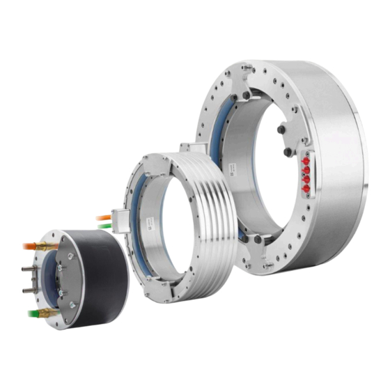
Page 29: Description Of The Motor
Description of the motor 1FW6 built-in torque motor Figure 3-1 1FW6 built-in torque motors with cooling jacket (left) and with integrated cooling (right) 1FW6 Built-in torque motors Configuration Manual, 09/2022, A5E52220645B AA... - Page 30 Description of the motor Overview of the 1FW6 built-in torque motor product family For each of the built-in torque motors described in the following tables, there are separate Operating Instructions and a separate Configuration Manual. Motor 1FW6 Standard 1FW6 High Speed built-in torque motors built-in torque motors Article No.
- Page 31 Description of the motor Motor Built-in torque motors Built-in torque motors 1FW6 naturally cooled 1FW6 external rotor Article No. 1FW6xx3-xxxxx-xxxx 1FW67xx-xxxxx-xxxx Photo Features High torque for positioning tasks with longer pauses High torque for positioning tasks and slow uninter‐ or for continuous running duty with lower torque rupted duty requirements...
-
Page 32: Overview
Description of the motor 3.1 Overview Overview Built-in SIMOTICS T-1FW6 torque motors are designed as built-in motors for use in low-speed direct drives with a high torque output. These built-in torque motors are liquid-cooled, permanent-magnet-excited, high-pole- number three-phase synchronous motors with hollow-shaft rotors. The motors are delivered as components that are subsequently built-in. -
Page 33: Technical Features And Ambient Conditions
Siemens offers its Application & Mechatronic Support Direct Motors service. Information on this topic is provided in the catalog. For more information, contact your local Siemens contact person. The Internet link on this topic is provided in the introduction under "Technical Support". - Page 34 Description of the motor 3.2 Technical features and ambient conditions Standards that are complied with Note The standards listed in this manual are not dated. You can take the currently relevant and valid dates from the Declaration of Conformity. The motors of the type series SIMOTICS S, SIMOTICS M, SIMOTICS L, SIMOTICS T, SIMOTICS A, called "SIMOTICS motor series"...
- Page 35 UL or cUL mark on the rating plate! Quality systems Siemens employs a quality management system that meets the requirements of ISO 9001 and ISO 14001. Certificates for SIMOTICS motors can be downloaded from the Internet at the following link: Certificates for SIMOTICS motors (https://support.industry.siemens.com/cs/ww/de/ps/13347/...
-
Page 36: Danger From Strong Magnetic Fields
Description of the motor 3.2 Technical features and ambient conditions 3.2.2 Danger from strong magnetic fields Occurrence of magnetic fields Motor components with permanent magnets generate very strong magnetic fields. In the no- current condition, the magnetic field strength of the motors comes exclusively from the magnetic fields of components equipped with permanent magnets. - Page 37 Description of the motor 3.2 Technical features and ambient conditions Risk to persons as a result of strong magnetic fields WARNING Risk of death as a result of permanent magnet fields The permanent magnets in the motors represents a danger for people with active medical implants, who come close to the motors.
- Page 38 Description of the motor 3.2 Technical features and ambient conditions WARNING Risk of rotor permanent magnets causing crushing injuries The forces of attraction of magnetic rotors act on materials that can be magnetized. The forces of attraction increase significantly close to the rotor. The response threshold of 3 mT for risk of injury through attraction and causing a projectile effect is reached at a distance of 100 mm (Directive 2013/35/EU).
-
Page 39: Technical Features
Description of the motor 3.2 Technical features and ambient conditions • To free jammed parts of the body (e.g. hands, fingers, feet), pull apart components that are clamped together. – Do this using the non-magnetic hammer to drive the non-magnetic wedges into the separating rift. - Page 40 Description of the motor 3.2 Technical features and ambient conditions Technical feature Version Cooling method Water cooling • Jacket cooling: sizes 1FW6090, 1FW6130, 1FW6150 • Integrated cooling (1 cooling circuit): frame sizes 1FW6050 and 1FW6060 • Integrated cooling (2 cooling circuits): frame sizes 1FW6160, 1FW6190, 1FW6230, 1FW6290 Pressure in the cooling circuit Max.
- Page 41 Description of the motor 3.2 Technical features and ambient conditions Technical feature Version Connection, electrical Cable outlet • Axial • Radial towards the outside – Not for 1FW6050 and 1FW6060 • Tangential – Not for motors with single cores Connection types •...
-
Page 42: Defining The Direction Of Rotation
Description of the motor 3.2 Technical features and ambient conditions 3.2.4 Defining the direction of rotation Direction of rotation If the built-in torque motor is connected with a phase sequence U-V-W, and is fed from a three- phase system with a clockwise phase sequence, then the rotor rotates clockwise. You can identify the direction of rotation by viewing the DE of the built-in torque motor. -
Page 43: Scope Of Delivery
Description of the motor 3.2 Technical features and ambient conditions Ambient parameter Unit Value Low air pressure 78.4 High air pressure Solar radiation (insolation) Thermal radiation Air movement Condensation Not permissible Wind-driven precipitation (rain, snow, hail, etc.) Water (other than rain) See degree of protection Formation of ice... -
Page 44: Preassembled Built-In Torque Motor With Integrated Cooling
Description of the motor 3.2 Technical features and ambient conditions • 2 rating plates • Safety instructions Note Supplied as individual components Stator and rotor as individual components are supplied without transport locks with spacers and screws. A spacer foil is supplied with stators as individual components. 3.2.6.2 Preassembled built-in torque motor with integrated cooling •... -
Page 45: Derating Factors
Description of the motor 3.3 Derating factors Table 3-4 Prohibit signs provided according to BGV A8 and DIN EN ISO 7010 and their significance Sign Meaning Sign Meaning No access for No access for persons with persons with pacemakers metal implants or implanted (P014) defibrillators (P007) Prohibited to carry/wear... -
Page 46: Selection And Ordering Data
Description of the motor 3.4 Selection and ordering data Selection and ordering data 3.4.1 Order designation The article number serves as order designation. The article number comprises a combination of digits and letters. When placing an order, it is sufficient just to specify the unique Article number. The Article number consists of three blocks that are separated by hyphens. -
Page 47: Standard 1Fw6 Built-In Torque Motor
Description of the motor 3.4 Selection and ordering data 3.4.1.1 Standard 1FW6 built-in torque motor 1FW6 Built-in torque motors Configuration Manual, 09/2022, A5E52220645B AA... -
Page 48: Stator As Individual Component
Description of the motor 3.4 Selection and ordering data 3.4.1.2 Stator as individual component 1FW6 Built-in torque motors Configuration Manual, 09/2022, A5E52220645B AA... -
Page 49: Rotor As Individual Component
Description of the motor 3.4 Selection and ordering data 3.4.1.3 Rotor as individual component 3.4.1.4 Ordering notes You can order a complete built-in torque motor (stator, rotor with transport locks) using a single order designation (article number). Spare parts and accessories can be ordered by specifying separate order designations (on this topic, see Chapter "Ordering examples (Page 47))". -
Page 50: Selection And Ordering Data 1Fw6
Description of the motor 3.4 Selection and ordering data Article number 1FW6090–0PB15–1JC3 Example 2: Stator and rotor premounted with transport locks; integrated cooling, radial cable outlet towards the outside, for SINAMICS S120 drive system, Motor Module with 18 A rated current,1 x PTC triplet 130 °C + 1 x Pt1000 as temperature sensors: Article number 1FW6190–0VB07–1JC3 Example 3: Cooling connection adapter (axial/radial) for sizes 1FW6160, 1FW619x and 1FW623x:... - Page 51 Description of the motor 3.4 Selection and ordering data Order desig. / Rated tor‐ Maximum tor‐ Rated cur‐ Maximum Rated speed Max. speed at que M rent current I Frame size max. torque in Nm in Nm in A in A in r/min MAX,MMAX in r/min...
- Page 52 Description of the motor 3.4 Selection and ordering data Order desig. / Rated tor‐ Maximum tor‐ Rated cur‐ Maximum Rated speed Max. speed at que M rent current I Frame size max. torque in Nm in Nm in A in A in r/min MAX,MMAX in r/min...
- Page 53 Description of the motor 3.4 Selection and ordering data Order desig. / Rated tor‐ Maximum tor‐ Rated cur‐ Maximum Rated speed Max. speed at que M rent current I Frame size max. torque in Nm in Nm in A in A in r/min MAX,MMAX in r/min...
- Page 54 Description of the motor 3.4 Selection and ordering data Water cooling with 35 °C intake temperature; speed and current values at converter DC link voltage U = 600 V (regulated) / converter output voltage (rms value) U = 425 V (regulated) a max Table 3-7 Built-in torque motors: overview (part 2 of 2) Order desig.
- Page 55 Description of the motor 3.4 Selection and ordering data Order desig. / size Rated power External di‐ Internal diam‐ Length of sta‐ Motor mass Moment of in‐ loss ameter of sta‐ eter of rotors ertia of rotor in kg tors in kW in mm in mm in mm...
- Page 56 Description of the motor 3.4 Selection and ordering data Order desig. / size Rated power External di‐ Internal diam‐ Length of sta‐ Motor mass Moment of in‐ loss ameter of sta‐ eter of rotors ertia of rotor in kg tors in kW in mm in mm in mm...
-
Page 57: Rating Plate Data
Description of the motor 3.5 Rating plate data Order desig. / size Rated power External di‐ Internal diam‐ Length of sta‐ Motor mass Moment of in‐ loss ameter of sta‐ eter of rotors ertia of rotor in kg tors in kW in mm in mm in mm... - Page 58 Description of the motor 3.5 Rating plate data Table 3-8 Data on the rating plate for 1FW6 built-in torque motors Position Description Type of motor Article No. Serial number Rated current I Rated speed n 2D code, contains the motor data Approvals/conformities Maximum speed n Motor version...
-
Page 59: Mechanical Properties
Mechanical properties Cooling The water cooling dissipates the stator winding power loss. • Connect the cooling ducts to the cooling circuit of a cooling device. You can find characteristic curves for the pressure drop of the coolant between the flow and return circuit of the coolers as a function of the flow rate in Chapter "Technical data and characteristics". -
Page 60: Cooling Circuits
Mechanical properties 4.1 Cooling 4.1.1 Cooling circuits Cooling circuit requirements Avoid algae growth by using suitable chemical agents and opaque water hoses or tubes. We recommend that the cooling circuits be designed as closed systems. The maximum permissible pressure is 10 bar. NOTICE Blocked and clogged cooling circuits Cooling circuits can become blocked and clogged as a result of pollution and longer-term... - Page 61 Mechanical properties 4.1 Cooling Example for interconnecting cooling circuits The following diagram shows an example of the cooling circuits of 2 stators with main and precision cooler connected in parallel. Due to the chosen positions for the water intake (IN) and the water outlet (OUT), all cooling circuits contain an even flow. As far as cooling is concerned, it does not make any difference in which direction the coolant flows through the cooling circuit.
- Page 62 Mechanical properties 4.1 Cooling Materials used in the cooling circuits of torque motors Table 4-1 Materials in the cooling circuits of torque motors (not including the material used for the connections) Cooling jacket Integrated cooling Integrated cooling Cooling connection adapter (main cooler) (precision cooler) 1FW6090, 1FW6130: 1FW6050, 1FW6060:...
- Page 63 Mechanical properties 4.1 Cooling Coolant inlet temperature NOTICE Corrosion in the machine Condensation can lead to corrosion in the machine. • Choose inlet temperatures that prevent condensation from forming on the surface of the motor. Condensation does not occur if the intake temperature T is higher than the VORL ambient temperature - or corresponds to the ambient temperature.
-
Page 64: Coolant
Mechanical properties 4.1 Cooling The cooling power is calculated from the sum of the power losses of the connected motors. Adapt the pump power to the specified flow and pressure loss of the cooling circuit. For a list of companies from whom you can obtain heat exchanger units, see the appendix. Dimensioning the heat-exchanger unit The power loss generated in the motor during continuous operation causes a thermal flow to take place. - Page 65 Mechanical properties 4.1 Cooling Use water with anti-corrosion protection agent If you use water with corrosion protection agent as coolant, you can avoid scaling and the formation of algae and slime as well as corrosion. This allows you to avoid the following damage and/or faults, for example: •...
-
Page 66: Degree Of Protection
Mechanical properties 4.3 Vibration response Recommended manufacturers are listed in the Appendix. Degree of protection NOTICE Damage to the motor caused by pollution If the area where the motor is installed is polluted and dirty, then the motor can malfunction and clog up. •... -
Page 67: Noise Emission
Mechanical properties 4.5 Service and inspection intervals Noise emission WARNING Hearing damage Hearing damage may occur if the motor exceeds a sound pressure level of 70 dB (A) due to the type of mounting or pulse frequency. • Reduce the sound pressure level by implementing sound damping and/or soundproofing measures. - Page 68 Mechanical properties 4.5 Service and inspection intervals WARNING Risk of death and crushing as a result of permanent magnet fields Severe injury and material damage can result if you do not take into consideration the safety instructions relating to permanent magnet fields. •...
- Page 69 Mechanical properties 4.5 Service and inspection intervals WARNING Risk of burning when touching hot surfaces There is a risk of burning when touching hot surfaces immediately after the motor has been operational. • Wait until the motor has cooled down. WARNING Danger to life if the cooling system bursts The motor will overheat if it is operated without cooling.
- Page 70 Risk of death, serious personal injury and/or material damage when carrying out disassembly work. • When carrying out disassembly work, observe the information in Chapter "Decommissioning and disposal " in the operating instructions "SIMOTICS T-1FW6 built-in motors." The motors have been designed for a long service life. Carefully ensure that maintenance work is correctly performed, e.g.
-
Page 71: Maintenance Work
If incorrect changes or corrective maintenance are carried out by you or a third party on the contractual objects, then for these and the consequential damages, no claims can be made against Siemens regarding personal injury or material damage. Technical Support is available for any questions you might have. Contact data is provided in the introduction. - Page 72 Mechanical properties 4.5 Service and inspection intervals As a result of their inherent principle of operation, the motors are always wear-free. To ensure that the motor functions properly and remains free of wear, the following maintenance work needs to be carried out: •...
-
Page 73: Checking The Insulation Resistance
Mechanical properties 4.5 Service and inspection intervals 4.5.3 Checking the insulation resistance Notes for checking the insulation resistance Installation inspection, preventive maintenance and troubleshooting are examples of required checking of the insulation resistance on a machine/system with direct drives or directly on the motors. -
Page 74: Inspection And Change Intervals For The Coolant
Mechanical properties 4.5 Service and inspection intervals 4.5.4 Inspection and change intervals for the coolant Inspection and change intervals for the coolant You must coordinate inspection and change intervals for the coolant with the manufacturer of the cooling equipment and with the manufacturer of the anti-corrosion agent. 1FW6 Built-in torque motors Configuration Manual, 09/2022, A5E52220645B AA... -
Page 75: Motor Components And Options
Motor components and options Motor components 5.1.1 Motor design The built-in torque motor contains the following components: • Stator The stator comprises an iron core and a 3-phase winding. The winding is potted to ensure that the power loss can be dissipated more effectively. For liquid cooling, the motor uses water as coolant (main cooler). - Page 76 Motor components and options 5.1 Motor components ① Stator with cooling jacket ② Rotor with permanent magnets ③ Transport locks ④ Electrical connections Figure 5-1 Motor components of the 1FW6090, 1FW6130 and 1FW6150 built-in torque motors with cooling jacket 1FW6 Built-in torque motors Configuration Manual, 09/2022, A5E52220645B AA...
-
Page 77: Motors With Integrated Cooling
Motor components and options 5.1 Motor components 5.1.1.2 Motors with integrated cooling Motors with integrated single-circuit cooling These motors have an integrated single-circuit cooling system that is ready to be connected. Further, they are compact, and can therefore be simply integrated into a machine. ①... -
Page 78: Cooling Method
Motor components and options 5.1 Motor components ① Stator with integrated cooling ② Rotor with permanent magnets ③ Transport lock ④ Electrical connections ⑤ Cooler connection Figure 5-3 Motor components of the 1FW6160 to 1FW6290 built-in torque motors with integrated cooling (2 cooling circuits) 5.1.1.3 Cooling method Built-in torque motor stators are equipped with a liquid cooler to dissipate power loss. -
Page 79: Temperature Monitoring And Thermal Motor Protection
Motor components and options 5.1 Motor components Frame size Cooling jacket Integrated cooling Integrated cooling with one cooling circuit with two cooling cir‐ (only main cooler) cuits (main cooler and preci‐ sion cooler) 1FW6230 1FW6290 5.1.2 Temperature monitoring and thermal motor protection 5.1.2.1 Temperature monitoring circuits Temp-S and Temp-F The motors are equipped with the two temperature monitoring circuits - Temp‑S and Temp‑F -... - Page 80 Motor components and options 5.1 Motor components Figure 5-4 PTC triplet To protect the power connection at the enclosure against thermal overload, an additional PTC 80 °C is connected in series with the PTC 130 °C triplet. For stators of 1FW6090-xxxxx-xxx2 to 1FW6290-xxxxx-xxx2, an additional PTC 80 °C is connected in series with the PTC 150 °C triplet.
- Page 81 Motor components and options 5.1 Motor components Temp‑F The Temp‑F temperature monitoring circuit comprises an individual temperature sensor. Contrary to Temp‑S, this temperature sensor only monitors one phase winding. As a consequence, Temp‑F is only used for monitoring the temperature and diagnosing the motor winding temperature.
-
Page 82: Technical Features Of Temperature Sensors
Motor components and options 5.1 Motor components 1FW6xxx-xxxxx-xxx1: with KTY 84 1FW6xxx-xxxxx-xxx2: with KTY 84 1FW6xxx-xxxxx-xxx3: with Pt1000 No direct connection of the temperature monitoring circuits WARNING Risk of electric shock if the temperature monitoring circuits are incorrectly connected In the case of a fault, circuits Temp‑S and Temp‑F do not provide safe electrical separation with respect to the power circuits. - Page 83 Motor components and options 5.1 Motor components Table 5-2 Technical data of the PTC temperature sensors Name Description Type PTC triplet acc. to DIN 44082 Individual PTC temperature sensor according to DIN 44081 Response threshold 150 °C ± 5 K (nominal response temperature ϑ 130 °C ± 5 K 80 °C ± 5 K Resistance when cold R (20 °C) in the PTC triplet See characteristic and in the individual PTC temperature sensor at -20 °C < T < ϑ...
- Page 84 Motor components and options 5.1 Motor components Technical features of the KTY 84 temperature sensor The KTY 84 has a progressive temperature resistance characteristic that is approximately linear. In addition, the KTY 84 has a low thermal capacity and provides good thermal contact with the motor winding.
-
Page 85: Encoders
Siemens will support you with dimensioning, designing and optimizing your machine by means of measurement-based and computer-based analyses. You can obtain additional information from your Siemens contacts. You will find the Internet link on "Technical Support" in the "Introduction". 1FW6 Built-in torque motors... - Page 86 Motor components and options 5.1 Motor components Encoder system In the following text, encoder systems stand for angular measuring systems, rotary encoders, encoders etc. The encoder system has a range of different functions: • Actual speed value encoder for closed-loop speed control •...
- Page 87 Figure 5-5 Performance-resolution diagram Note Siemens does not accept any warranty for the properties/features of third-party products. Note General mechanical conditions Take into account the permissible mechanical speed, limit frequency of the encoder and Control Unit. When configuring, mounting and adjusting the encoder refer to the appropriate...
- Page 88 As a consequence, a general recommendation for integrating the encoder cannot be given for all encoder types and axis concepts. To ensure that the encoder is optimally integrated into the mechanical structure, Siemens offers its Application & Mechatronic Support Direct Motors service, see Catalog. For additional information, contact your local Siemens office.
- Page 89 Motor components and options 5.1 Motor components Figure 5-6 Installation diagram (example) Note Additional mounting examples are provided in Chapter "Installation examples (Page 146)". 1FW6 Built-in torque motors Configuration Manual, 09/2022, A5E52220645B AA...
-
Page 90: Bearings
Motor components and options 5.1 Motor components 5.1.4 Bearings Selecting the bearing 1FW6 torque motors are built-in motors for directly driven rotary or swivel axes. To set up a complete drive unit, a bearing between the stator and rotor is required in addition to the phase- angle encoder system. - Page 91 Motor components and options 5.1 Motor components The design of mechanical braking systems depends on the maximum kinetic energy, that is, the maximum moment of inertia of the rotating mass and its maximum speed. Possible malfunctions Malfunctions can occur e.g. for: •...
-
Page 92: Options
Motor components and options 5.2 Options Deploying a holding brake Due to cogging torques, torque motors can be pulled into a preferable magnetic operating position if the motor is no longer supplied with power from the drive. If the drive is already at a standstill, this can cause unexpected movements in up to a half magnetic pole pitch in both directions. -
Page 93: Cooling Connection Adapter
Motor components and options 5.2 Options 5.2.2 Cooling connection adapter Note The cooling connection adapter is an option, and only fits for built-in torque motors with integrated cooling, for frame sizes 1FW6160, 1FW619x, 1FW623x and 1FW6290. When required, order the cooling connection adapter. 5.2.3 Plug connector Connector type... - Page 94 Motor components and options 5.2 Options 1FW6 Built-in torque motors Configuration Manual, 09/2022, A5E52220645B AA...
-
Page 95: Configuration
Siemens will support you with dimensioning, designing and optimizing your machine by means of measurement-based and computer-based analyses. You can obtain additional information from your Siemens contacts. You will find the Internet link on "Technical Support" in the "Introduction". Configuring software 6.1.1... -
Page 96: Sinamics Startdrive Drive/Commissioning Software
The SINAMICS Startdrive commissioning tool offers • Commissioning • Optimization • Diagnostics You can find additional information that you can download in the Internet at SINAMICS Startdrive (https://support.industry.siemens.com/cs/ww/en/view/109794362). Table 6-1 Article number for the SINAMICS Startdrive commissioning tool Commissioning tool Article no. of the DVD... - Page 97 Configuration 6.2 Configuring workflow Procedure Selecting the motors is generally an iterative process because - in particular with highly-dynamic direct drives - the moment of inertia of the motor type is a factor in determining the required torques. 1FW6 Built-in torque motors Configuration Manual, 09/2022, A5E52220645B AA...
-
Page 98: General Mechanical Conditions
Configuration 6.2 Configuring workflow 6.2.1 General mechanical conditions Moment of inertia The kinetic energy generated by a rotating body is directly proportional to its moment of inertia J in kgm . The moment of inertia takes into account the rotating mass and its spatial distribution across the entire volume of the body with respect to the rotary axes. - Page 99 Configuration 6.2 Configuring workflow Short-time duty S2 For short-time duty S2 the load duration is so short that the final thermal state is not reached. The subsequent zero-current break is so long that the motor practically cools down completely. NOTICE Motor overload An excessively high load can lead to shutdown, or if the temperature sensors are not correctly evaluated, then the motor could be destroyed.
- Page 100 Configuration 6.2 Configuring workflow Intermittent duty S3 With intermittent duty S3, periods of load time Δt with constant current alternate with periods of downtime Δt with no current feed. The motor heats up during the load time and then cools down again while at standstill. After a sufficient number of duty cycles with cycle duration Δt = Δt + Δt...
- Page 101 Configuration 6.2 Configuring workflow Motional sequence The motional sequence can be specified as a rotation angle-time diagram, angular velocity-time diagram, speed-time diagram, or angular acceleration-time diagram. The torques resulting from the motional sequence (accelerating torque M ) are proportional with respect to the angular acceleration α...
-
Page 102: Torque-Time Diagram
Configuration 6.2 Configuring workflow 6.2.3 Torque-time diagram Required motor torque The required motor torque M is always the sum of the individual torques. The sign in front of the torque specifications must always be taken into account. : Accelerating torque : Machining torque : Frictional torque Determining the required motor torque The frictional torque characteristic can be determined on the basis of the speed characteristic. - Page 103 Configuration 6.2 Configuring workflow Figure 6-3 Individual torques that occur - and the resulting required motor torque -M for a torque drive as characteristic with respect to time In addition to the peak torque M , the required rms torque M of the motor is also a mMAX decisive factor when dimensioning the motor.
-
Page 104: Selecting Motors
Configuration 6.2 Configuring workflow Figure 6-4 Motor torque-time diagram 6.2.4 Selecting motors Select a suitable torque motor using the values determined for the peak torque M and rms mMAX torque M of the duty cycle. Important points when selecting a motor • If more than one torque motor is used to generate torque for a specific axis, the values of the maximum torques M and rated torques M of each of the individual motors must be added... -
Page 105: Uneven Current Load
Configuration 6.2 Configuring workflow 6.2.5 Uneven current load If the current load of the three phases is continuously uneven, the motor must only be operated at no more than approx. 70 % of its rated torque. See also M * in Chapter "Technical data and characteristics". - Page 106 Configuration 6.2 Configuring workflow Determining the motor torque-speed diagram If the motor torque-speed diagram is not available, then determine the motor torque-speed diagram from the following data taken from the "Motor torque speed diagram" figure. • Maximum torque M with the associated speed n MAX,MMAX •...
-
Page 107: Torque-Speed Requirements
Configuration 6.2 Configuring workflow 6.2.7 Torque-speed requirements Fulfilling the torque-speed requirements If the selected torque motor cannot fulfill the torque-speed requirements, the following options are available: • Larger motor If an operating point in the range A is required, a motor with a larger diameter and/or longer length is required (see motor 2 in the following diagram). -
Page 108: Checking The Moments Of Inertia
Configuration 6.2 Configuring workflow • Field weakening operation If an operating point in range C is required, then the motor must be operated in the field weakening range (see the following diagram). Advantage: Significantly higher speeds are possible. Disadvantage: The torques available are very low. A lower current is required, refer to the description for field weakening operation in Chapter "Technical data and characteristics"... -
Page 109: Calculation Of The Required Infeed
Configuration 6.2 Configuring workflow NOTICE Damaged main insulation In systems where direct drives are used on controlled infeeds, electrical oscillations can occur with respect to ground potential. These oscillations are, among other things, influenced by: • The lengths of the cables •... -
Page 110: Voltage Protection Module
Configuration 6.3 Examples = P / (√3 • U • cosφ Line Line Line Line If the Active Infeed is operated according to the factory setting, i.e. with a line-side power factor of cosφ = 1, so that it draws only pure active power from the supply, then the Line formula can be simplified to = P... - Page 111 Configuration 6.3 Examples General conditions for positioning within a defined period • Moment of inertia in kgm : J = 5.1 kg m moved cylindrical mass m = 30 kg with equivalent radius r = 0.583 m; axis of rotation of the moved masses and the motor are identical;...
- Page 112 Configuration 6.3 Examples Figure 6-11 Idealized depiction of the traversing profile with angular acceleration α (t), angular velocity ω (t) and angle φ (t) Table 6-2 Functions of the individual sections in the traversing profile Section I Section II α (t) = α α...
- Page 113 Configuration 6.3 Examples The angle of rotation φ (t) increases in section I and in section II according to parabolic functions. This type of traversing profile allows the shortest positioning times. The required constant angular acceleration or angular deceleration can be calculated from the defined final angle φ...
- Page 114 Configuration 6.3 Examples A suitable motor can be selected from the "Built-in torque motors: overview" table in accordance with the following criteria: Maximum torque at least 367 Nm. Maximum speed (specifying the max. torque) as a minimum 100 r/min. Suitable motors are: 1FW6090-0PB15-2JC3 (diameter 230 mm, length 190 mm) 1FW6130-0PB05-1JC3 (diameter 310 mm, length 90 mm) The moment of inertia of the motor 1FW6090-0PB15-2JC3 is J = 0.0465 kgm The accelerating torque M...
-
Page 115: Installation
Configuration 6.4 Installation Each of these torques can have any value between + M and – M . The rms torque M this duty cycle can be calculated in Nm using the following formula: In this case, the cycle duration (Δt + Δt + Δt ) should not be longer than 10 % of the thermal time constant t... - Page 116 Configuration 6.4 Installation WARNING Risk of rotor permanent magnets causing crushing injuries The forces of attraction of magnetic rotors act on materials that can be magnetized. The forces of attraction increase significantly close to the rotor. The response threshold of 3 mT for risk of injury through attraction and causing a projectile effect is reached at a distance of 100 mm (Directive 2013/35/EU).
- Page 117 Configuration 6.4 Installation WARNING Electric shock caused by defective cables Defective connecting cables can cause an electric shock and/or material damage, e.g. by fire. • When installing the motor, make sure that the connection cables – are not damaged – are not under tension –...
-
Page 118: Forces That Occur Between The Stator And Rotor
Configuration 6.4 Installation CAUTION Risk of crushing when the rotor is installed There is a risk of crushing when the rotor of an installed torque motor rotates! • Wear safety gloves. • Take extreme care when performing any work. CAUTION Sharp edges and falling objects Sharp edges can cause cuts and falling objects can injure feet. - Page 119 Configuration 6.4 Installation Radial forces between the stator and rotor The following table shows the active radial forces in N per 0.1 mm centering error between the stator and rotor. The longer the active component, the greater the radial force. Table 6-3 Radial forces in N/0.1 mm with radial centering errors during installation ...
-
Page 120: Installation Device
Configuration 6.4 Installation Note When starting to insert the rotor into the stator, the axial forces of attraction between the stator and rotor are 4x to 5x higher. At the end of the removal of the rotor from the stator, the axial forces of attraction between the stator and rotor are 4x to 5x higher. - Page 121 Configuration 6.4 Installation 3. Insert the spacer film in the stator in such a way that approx. 1/4 of the spacer film protrudes. 1FW6 Built-in torque motors Configuration Manual, 09/2022, A5E52220645B AA...
- Page 122 Configuration 6.4 Installation 4. Carefully lower the rotor using the upper part of the installation device and carefully fit it into the lower part of the installation device in such a way that the rotor can be aligned centrically over the sleeve bearing and shaft in the stator. WARNING Risk of crushing when the rotor is lowered.
-
Page 123: Specification Of The Installation Side
Configuration 6.4 Installation 6. Fix the stator and rotor using the transport locks. To do this, tighten the bolts with the specified tightening torques according to the table "Required property classes and tightening torques for stator and rotor." 7. Remove the spacer foil. When the stator and rotor are correctly centered, the spacer film can be easily removed by hand. -
Page 124: Specifications For Integration In The Machine
Configuration 6.4 Installation Figure 6-13 A flange and B flange 6.4.5 Specifications for integration in the machine Fits for motors with integratedcooling Built-in torque motor stators with integrated cooling have a centering collar at both flanges. In the factory, the centering collars are machined with tolerance class f8 with respect to the nominal dimensions. -
Page 125: Specifications For Mounting Torque Motors
Configuration 6.4 Installation Installation with enclosure Installation without enclosure ① Free flange ② 1FW6 with integrated cooling ③ Mounting flange ④ Fit on the stator side: f8 ⑤ Fit on the machine side: H8 ⑥ Machine Figure 6-14 Installation types, 1FW6 stator with integrated cooling (schematic) 6.4.6 Specifications for mounting torque motors Mounting system... - Page 126 Configuration 6.4 Installation • To secure the screws, choose long clamping lengths l / d > 5 if possible; alternatively (if / d > 5 is not possible), check pretensioning of the screws at regular intervals (tighten with calibrated torque wrench). • Note the tightening torques specified in the table below. •...
- Page 127 Configuration 6.4 Installation Motor Screw Tightening torque (strength class) in Nm 1FW6290-xxB07-xxxx to M10 (8.8) 1FW6290-xxB15-xxxx 1FW6290-xxB20-xxxx M10 (10.9) 61.8 Note Friction value For the contact surface of the screw head and the screw thread, the friction value µ = 0.1 is taken as a basis.
-
Page 128: Procedure For Installing The Motor
Configuration 6.4 Installation 6.4.7 Procedure for installing the motor Sequence for installing the motor WARNING Risk of injury and material damage Injury and/or destruction of motor components can occur if you do not observe the specified sequence when installing the motor. •... - Page 129 Configuration 6.4 Installation Procedure 1. Prepare the mounting surfaces of the components to be mounted and the machine as follows: – Carefully remove machining debris, e.g. metal chips, dirt and foreign particles. – This point only applies to motors with cooling jacket, frame sizes 1FW6090, 1FW6130 and 1FW6150: Deburr and round off any interior drill holes (e.g.
-
Page 130: Mechanical Adjustment Angle And Emf Phase Position
Configuration 6.4 Installation 5. This point only applies to motors with cooling jackets, frame sizes 1FW6090, 1FW6130, and 1FW6150: Position the motor with the free flange surface pointing forward in the machined precisely dimensioned bore of the machine housing. O-rings must not be pressed out of the groove or damaged during this step. Ensure that the motor does not become tilted in the installation space during installation. - Page 131 Configuration 6.4 Installation Figure 6-15 Mechanical adjustment angle for coupled motors Table 6-8 Interrelationship between the electrical and mechanical angle Frame size 5° electrical corresponds to mechanical 360° electrical corresponds to mechanical 1FW6050 0.4545° 32.72° 1FW6060 0.3333° 24.00° 1FW6090 0.2273° 16.36° 1FW6130 0.1515°...
-
Page 132: Cooler Connection
Configuration 6.4 Installation Frame size 5° electrical corresponds to mechanical 360° electrical corresponds to mechanical 1FW6230 0.1020° 7.35° 1FW6290 0.1190° 8.57° More information is provided in Chapter "Coupled motors (Page 491)". 6.4.9 Cooler connection The connectors can generally be installed using standard tools. First determine the sum of the pressure losses of the individual cooling components and the associated piping. - Page 133 Configuration 6.4 Installation Figure 6-16 Cooler connection for 1FW6090 and 1FW6130 (example) Figure 6-17 Cooler connection for 1FW6150 (example) 1FW6 Built-in torque motors Configuration Manual, 09/2022, A5E52220645B AA...
-
Page 134: Cooler Connection For Motors With Integrated Cooling
Configuration 6.4 Installation 6.4.9.2 Cooler connection for motors with integrated cooling Note Significance of the 7th position in the Article No. In this chapter, for certain 1FW6 Article Nos., an "x" should be inserted at the 7th position. This means that the information provided for the specific cooler connections and the cooling connection adapter for the particular frame size also applies to 1FW6 High Speed built-in torque motors. - Page 135 Locking plate for the coolant connection It is only permissible to remove the locking plate for the coolant connection for 1FW6050 and 1FW6060 motors for service purposes, and this must be done by a Siemens Service Center employee. Cooling connection adapter (option) Figure 6-18...
- Page 136 Configuration 6.4 Installation Cooler connection for 1FW6050 and 1FW6060 Figure 6-19 Axial cooler connection with sleeve for 1FW6050 and 1FW6060 Note Manufacturer's recommendations for plug-in connections for the coolant connection are provided in the Appendix. 1FW6 Built-in torque motors Configuration Manual, 09/2022, A5E52220645B AA...
- Page 137 Configuration 6.4 Installation Cooler connection for 1FW6160, 1FW619x and 1FW623x Figure 6-20 Cooling connection plate for 1FW6160, 1FW619x, 1FW623x Figure 6-21 Axial cooler connection with cooling connection adapter (option) for 1FW6160, 1FW619x, 1FW623x 1FW6 Built-in torque motors Configuration Manual, 09/2022, A5E52220645B AA...
- Page 138 Configuration 6.4 Installation Figure 6-22 Outer radial cooler connection with cooling connection adapter (option) for 1FW6160, 1FW619x, 1FW623x 1FW6 Built-in torque motors Configuration Manual, 09/2022, A5E52220645B AA...
- Page 139 Configuration 6.4 Installation Figure 6-23 Cooling connection adapter (option) for 1FW6160, 1FW619x, 1FW623x 1FW6 Built-in torque motors Configuration Manual, 09/2022, A5E52220645B AA...
- Page 140 Configuration 6.4 Installation Cooler connection for 1FW6290 Figure 6-24 Cooling connection plate for 1FW6290 1FW6 Built-in torque motors Configuration Manual, 09/2022, A5E52220645B AA...
- Page 141 Configuration 6.4 Installation Figure 6-25 Axial cooler connection with cooling connection adapter (option) for 1FW6290 1FW6 Built-in torque motors Configuration Manual, 09/2022, A5E52220645B AA...
- Page 142 Configuration 6.4 Installation Figure 6-26 Outer radial cooler connection with cooling connection adapter (option) for 1FW6290 1FW6 Built-in torque motors Configuration Manual, 09/2022, A5E52220645B AA...
-
Page 143: Hoses For The Cooling System
Configuration 6.4 Installation Figure 6-27 Cooling connection adapter (option) for 1FW6290 6.4.9.3 Hoses for the cooling system The hoses for the cooling system must be highly resistant to the coolant, flexible, and abrasion proof. You can only select the hoses for the cooling system if all of the materials involved in the cooling are known along with the associated constraints. -
Page 144: Cooling Connection Adapter
Configuration 6.4 Installation Note Siemens does not accept any warranty for the properties/features of third-party products. 6.4.9.4 Cooling connection adapter Mounting the cooler connection adapter for motors with integrated cooling The components required for connecting the cooler for motors with integrated cooling can usually be mounted with standard tools. - Page 145 Configuration 6.4 Installation Figure 6-28 Mounting the cooling connection adapter 1FW6160, 1FW619x, 1FW6230 1FW6 Built-in torque motors Configuration Manual, 09/2022, A5E52220645B AA...
- Page 146 Configuration 6.4 Installation Figure 6-29 Installing the cooling connection adapter 1FW6290 1FW6 Built-in torque motors Configuration Manual, 09/2022, A5E52220645B AA...
-
Page 147: Checking The Work Performed
Configuration 6.4 Installation 6.4.10 Checking the work performed Checking the mounting work After installation has been completed, check that the rotor can freely rotate. Note that with short-circuited motor phases, the rotor is difficult to turn - even if no mechanical resistance is otherwise present. -
Page 148: Installation Examples
Configuration 6.4 Installation 6.4.11 Installation examples Note The examples provided below are not necessarily complete nor are they suitable for all applications. Note that the rotor and stator are secured on one side on the machine construction. Depending on the machine construction, the stator can be secured on the same side as the rotor or on the opposite side. - Page 149 Configuration 6.4 Installation Figure 6-30 Rotary table with torque motor with integrated cooling 1FW6 Built-in torque motors Configuration Manual, 09/2022, A5E52220645B AA...
- Page 150 Configuration 6.4 Installation Figure 6-31 Rotary table with torque motor with cooling jacket 1FW6 Built-in torque motors Configuration Manual, 09/2022, A5E52220645B AA...
- Page 151 Configuration 6.4 Installation Figure 6-32 Part-turn actuator with torque motor with integrated cooling 1FW6 Built-in torque motors Configuration Manual, 09/2022, A5E52220645B AA...
- Page 152 Configuration 6.4 Installation Figure 6-33 Installing a torque motor with integrated cooling on the shaft extension of a part-turn actuator 1FW6 Built-in torque motors Configuration Manual, 09/2022, A5E52220645B AA...
-
Page 153: Technical Data And Characteristics
Technical data and characteristics The technical data and characteristics for the 1FW6 Built-in torque motors are specified in this Chapter. This data collection provides the motor data required for configuration and contains a number of additional data for more detailed calculations for detailed analyses and problem analyses. - Page 154 Technical data and characteristics 7.1 Explanations Boundary conditions Converter DC link voltage (direct voltage value). Comment: U is the maximum permissible converter output voltage. a max Maximum intake temperature of the water cooler for the main cooler and precision VORL cooler if the motor is to be utilized up to its rated torque M .
- Page 155 Technical data and characteristics 7.1 Explanations Maximum permissible operating speed. Maximum speed at which the motor can supply the maximum torque M MAX,MMAX Maximum speed, where a Voltage Protection Module VPM is not required. MAX,INV No-load speed; max. speed without load. MAX,0 Torque for speed n = 1 r/min at which the load and power loss are still evenly distributed across all three motor phases.
- Page 156 Technical data and characteristics 7.1 Explanations Figure 7-1 Thermal time constant Number of pole pairs of the motor. Cogging torque. This is the torque generated by the interaction between the lami‐ nated core and permanent magnets at the air gap in stators that have been discon‐ nected from the power supply.
- Page 157 Technical data and characteristics 7.1 Explanations Data for main motor cooler Maximum thermal power that is dissipated by the main cooler when the motor is H,MAX utilized up to the rated torque M and at the rated temperature T Recommended minimum volume flow rate in the main cooler to achieve the rated H,MIN torque M ΔT...
- Page 158 Technical data and characteristics 7.1 Explanations Figure 7-3 Sample characteristic: "Pressure losses in the main cooler over volume flow rate" Data for precision motor cooler Maximum heat loss dissipated by the precision cooler when the motor is utilized up P,MAX to its rated torque M and at rated temperature T Recommended minimum volume flow rate in the precision cooler to achieve a min‐...
-
Page 159: Explanations Of The Characteristic Curves
Technical data and characteristics 7.1 Explanations 7.1.2 Explanations of the characteristic curves Torque-speed diagram with field weakening S1 duty S1 duty with field weakening S3 duty, cycle duration should not exceed 10% of the thermal time constant t S3 duty with field weakening, cycle duration should not exceed 10% of the thermal time constant t Voltage limit characteristic Limit characteristic for S1 duty Voltage limit characteristic with field weakening... - Page 160 Technical data and characteristics 7.1 Explanations can be reached when motoring, are located to the left or below the "voltage limiting characteristic with field weakening" and to the right of the "voltage limiting characteristic". Note Above a certain speed, a Voltage Protection Module VPM is required; refer to Chapter "Voltage Protection Module (Page 108)"...
-
Page 161: Data Sheets And Characteristics
Technical data and characteristics 7.2 Data sheets and characteristics Short-circuit braking torque For each frame size and active part length, the short-circuit braking torque M is specified as the "short-circuit braking torque versus speed" characteristic. Figure 7-7 Short-circuit braking torque speed diagram (example) Data sheets and characteristics Table 7-1 Color coding of the M-n characteristics in the diagrams... -
Page 162: 1Fw6050-Xxxxx-Xxxx
Technical data and characteristics 7.2 Data sheets and characteristics 7.2.1 1FW6050-xxxxx-xxxx Data sheet 1FW6050-xxB03-xxxx Table 7-2 1FW6050-xxB03-0Fxx Technical data Symbol Unit -xxB03-0Fxx 1FW6050 Boundary conditions DC link voltage Water cooling inlet temperature °C ... - Page 163 Technical data and characteristics 7.2 Data sheets and characteristics Technical data Symbol Unit -xxB03-0Fxx 1FW6050 Maximum dissipated thermal power 0.698 H,MAX Recommended minimum volume flow V̇ l/min H,MIN Temperature increase of the coolant ΔT 3.86 ...
- Page 164 Technical data and characteristics 7.2 Data sheets and characteristics Torque M with respect to speed n Short-circuit braking torque M with respect to speed n 1FW6 Built-in torque motors Configuration Manual, 09/2022, A5E52220645B AA...
- Page 165 Technical data and characteristics 7.2 Data sheets and characteristics Main cooler - pressure losses Δp with respect to the volume flow rate V̇ Rotor power loss P with respect to speed n 1FW6 Built-in torque motors Configuration Manual, 09/2022, A5E52220645B AA...
- Page 166 Technical data and characteristics 7.2 Data sheets and characteristics Data sheet 1FW6050-xxB05-xxxx Table 7-3 1FW6050-xxB05-0Fxx Technical data Symbol Unit -xxB05-0Fxx 1FW6050 Boundary conditions DC link voltage Water cooling inlet temperature °C ...
- Page 167 Technical data and characteristics 7.2 Data sheets and characteristics Technical data Symbol Unit -xxB05-0Fxx 1FW6050 Temperature increase of the coolant ΔT Pressure drop Δp Characteristics for 1FW6050-xxB05-xxxx Torque M with respect to speed n 1FW6 Built-in torque motors Configuration Manual, 09/2022, A5E52220645B AA...
- Page 168 Technical data and characteristics 7.2 Data sheets and characteristics Torque M with respect to speed n Short-circuit braking torque M with respect to speed n 1FW6 Built-in torque motors Configuration Manual, 09/2022, A5E52220645B AA...
- Page 169 Technical data and characteristics 7.2 Data sheets and characteristics Main cooler - pressure losses Δp with respect to the volume flow rate V̇ Rotor power loss P with respect to speed n 1FW6 Built-in torque motors Configuration Manual, 09/2022, A5E52220645B AA...
- Page 170 Technical data and characteristics 7.2 Data sheets and characteristics Data sheet 1FW6050-xxB07-xxxx Table 7-4 1FW6050-xxB07-0Fxx, 1FW6050-xxB07-0Kxx Technical data Symbol Unit -xxB07-0Fxx -xxB07-0Kxx 1FW6050 Boundary conditions DC link voltage Water cooling inlet temperature °C VORL Rated temperature of winding °C...
- Page 171 Technical data and characteristics 7.2 Data sheets and characteristics Technical data Symbol Unit -xxB07-0Fxx -xxB07-0Kxx 1FW6050 Temperature increase of the coolant ΔT 4.32 4.19 Pressure drop Δp 0.276 0.276 Characteristics for 1FW6050-xxB07-xxxx Torque M with respect to speed n 1FW6 Built-in torque motors Configuration Manual, 09/2022, A5E52220645B AA...
- Page 172 Technical data and characteristics 7.2 Data sheets and characteristics Torque M with respect to speed n Torque M with respect to speed n 1FW6 Built-in torque motors Configuration Manual, 09/2022, A5E52220645B AA...
- Page 173 Technical data and characteristics 7.2 Data sheets and characteristics Torque M with respect to speed n Short-circuit braking torque M with respect to speed n 1FW6 Built-in torque motors Configuration Manual, 09/2022, A5E52220645B AA...
- Page 174 Technical data and characteristics 7.2 Data sheets and characteristics Main cooler - pressure losses Δp with respect to the volume flow rate V̇ Rotor power loss P with respect to speed n 1FW6 Built-in torque motors Configuration Manual, 09/2022, A5E52220645B AA...
- Page 175 Technical data and characteristics 7.2 Data sheets and characteristics Data sheet 1FW6050-xxB10-xxxx Table 7-5 1FW6050-xxB10-0Kxx Technical data Symbol Unit -xxB10-0Kxx 1FW6050 Boundary conditions DC link voltage Water cooling inlet temperature °C ...
- Page 176 Technical data and characteristics 7.2 Data sheets and characteristics Technical data Symbol Unit -xxB10-0Kxx 1FW6050 Temperature increase of the coolant ΔT 4.38 Pressure drop Δp 0.416 Characteristics for 1FW6050-xxB10-xxxx Torque M with respect to speed n 1FW6 Built-in torque motors Configuration Manual, 09/2022, A5E52220645B AA...
- Page 177 Technical data and characteristics 7.2 Data sheets and characteristics Torque M with respect to speed n Short-circuit braking torque M with respect to speed n 1FW6 Built-in torque motors Configuration Manual, 09/2022, A5E52220645B AA...
- Page 178 Technical data and characteristics 7.2 Data sheets and characteristics Main cooler - pressure losses Δp with respect to the volume flow rate V̇ Rotor power loss P with respect to speed n 1FW6 Built-in torque motors Configuration Manual, 09/2022, A5E52220645B AA...
- Page 179 Technical data and characteristics 7.2 Data sheets and characteristics Data sheet 1FW6050-xxB15-xxxx Table 7-6 1FW6050-xxB15-0Kxx, 1FW6050-xxB15-1Jxx Technical data Symbol Unit -xxB15-0Kxx -xxB15-1Jxx 1FW6050 Boundary conditions DC link voltage Water cooling inlet temperature °C VORL Rated temperature of winding °C...
- Page 180 Technical data and characteristics 7.2 Data sheets and characteristics Technical data Symbol Unit -xxB15-0Kxx -xxB15-1Jxx 1FW6050 Temperature increase of the coolant ΔT Pressure drop Δp 0.705 0.705 Characteristics for 1FW6050-xxB15-xxxx Torque M with respect to speed n 1FW6 Built-in torque motors Configuration Manual, 09/2022, A5E52220645B AA...
- Page 181 Technical data and characteristics 7.2 Data sheets and characteristics Torque M with respect to speed n Torque M with respect to speed n 1FW6 Built-in torque motors Configuration Manual, 09/2022, A5E52220645B AA...
- Page 182 Technical data and characteristics 7.2 Data sheets and characteristics Torque M with respect to speed n Short-circuit braking torque M with respect to speed n 1FW6 Built-in torque motors Configuration Manual, 09/2022, A5E52220645B AA...
- Page 183 Technical data and characteristics 7.2 Data sheets and characteristics Main cooler - pressure losses Δp with respect to the volume flow rate V̇ Rotor power loss P with respect to speed n 1FW6 Built-in torque motors Configuration Manual, 09/2022, A5E52220645B AA...
-
Page 184: 1Fw6060-Xxxxx-Xxxx
Technical data and characteristics 7.2 Data sheets and characteristics 7.2.2 1FW6060-xxxxx-xxxx Data sheet 1FW6060-xxB03-xxxx Table 7-7 1FW6060-xxB03-0Fxx Technical data Symbol Unit -xxB03-0Fxx 1FW6060 Boundary conditions DC link voltage Water cooling inlet temperature °C ... - Page 185 Technical data and characteristics 7.2 Data sheets and characteristics Technical data Symbol Unit -xxB03-0Fxx 1FW6060 Maximum dissipated thermal power 0.647 H,MAX Recommended minimum volume flow V̇ l/min 3.46 H,MIN Temperature increase of the coolant ΔT 2.69 ...
- Page 186 Technical data and characteristics 7.2 Data sheets and characteristics Torque M with respect to speed n Short-circuit braking torque M with respect to speed n 1FW6 Built-in torque motors Configuration Manual, 09/2022, A5E52220645B AA...
- Page 187 Technical data and characteristics 7.2 Data sheets and characteristics Main cooler - pressure losses Δp with respect to the volume flow rate V̇ Rotor power loss P with respect to speed n 1FW6 Built-in torque motors Configuration Manual, 09/2022, A5E52220645B AA...
- Page 188 Technical data and characteristics 7.2 Data sheets and characteristics Data sheet 1FW6060-xxB05-xxxx Table 7-8 1FW6060-xxB05-0Fxx, 1FW6060-xxB05-0Kxx Technical data Symbol Unit -xxB05-0Fxx -xxB05-0Kxx 1FW6060 Boundary conditions DC link voltage Water cooling inlet temperature °C VORL Rated temperature of winding °C...
- Page 189 Technical data and characteristics 7.2 Data sheets and characteristics Technical data Symbol Unit -xxB05-0Fxx -xxB05-0Kxx 1FW6060 Temperature increase of the coolant ΔT 2.96 2.99 Pressure drop Δp 0.74 0.74 Characteristics for 1FW6060-xxB05-xxxx Torque M with respect to speed n 1FW6 Built-in torque motors Configuration Manual, 09/2022, A5E52220645B AA...
- Page 190 Technical data and characteristics 7.2 Data sheets and characteristics Torque M with respect to speed n Torque M with respect to speed n 1FW6 Built-in torque motors Configuration Manual, 09/2022, A5E52220645B AA...
- Page 191 Technical data and characteristics 7.2 Data sheets and characteristics Torque M with respect to speed n Short-circuit braking torque M with respect to speed n 1FW6 Built-in torque motors Configuration Manual, 09/2022, A5E52220645B AA...
- Page 192 Technical data and characteristics 7.2 Data sheets and characteristics Main cooler - pressure losses Δp with respect to the volume flow rate V̇ Rotor power loss P with respect to speed n 1FW6 Built-in torque motors Configuration Manual, 09/2022, A5E52220645B AA...
- Page 193 Technical data and characteristics 7.2 Data sheets and characteristics Data sheet 1FW6060-xxB07-xxxx Table 7-9 1FW6060-xxB07-0Fxx, 1FW6060-xxB07-0Kxx, 1FW6060-xxB07-1Jxx Technical data Symbol Unit -xxB07-0Fxx -xxB07-0Kxx -xxB07-1Jxx 1FW6060 Boundary conditions DC link voltage Water cooling inlet temperature °C VORL Rated temperature of winding °C Data at the rated operating point...
- Page 194 Technical data and characteristics 7.2 Data sheets and characteristics Technical data Symbol Unit -xxB07-0Fxx -xxB07-0Kxx -xxB07-1Jxx 1FW6060 Temperature increase of the coolant ΔT 3.12 3.21 Pressure drop Δp 1.03 1.03 1.03 Characteristics for 1FW6060-xxB07-xxxx Torque M with respect to speed n 1FW6 Built-in torque motors Configuration Manual, 09/2022, A5E52220645B AA...
- Page 195 Technical data and characteristics 7.2 Data sheets and characteristics Torque M with respect to speed n Torque M with respect to speed n 1FW6 Built-in torque motors Configuration Manual, 09/2022, A5E52220645B AA...
- Page 196 Technical data and characteristics 7.2 Data sheets and characteristics Torque M with respect to speed n Torque M with respect to speed n 1FW6 Built-in torque motors Configuration Manual, 09/2022, A5E52220645B AA...
- Page 197 Technical data and characteristics 7.2 Data sheets and characteristics Torque M with respect to speed n Short-circuit braking torque M with respect to speed n 1FW6 Built-in torque motors Configuration Manual, 09/2022, A5E52220645B AA...
- Page 198 Technical data and characteristics 7.2 Data sheets and characteristics Main cooler - pressure losses Δp with respect to the volume flow rate V̇ Rotor power loss P with respect to speed n 1FW6 Built-in torque motors Configuration Manual, 09/2022, A5E52220645B AA...
- Page 199 Technical data and characteristics 7.2 Data sheets and characteristics Data sheet 1FW6060-xxB10-xxxx Table 7-10 1FW6060-xxB10-0Kxx, 1FW6060-xxB10-1Jxx Technical data Symbol Unit -xxB10-0Kxx -xxB10-1Jxx 1FW6060 Boundary conditions DC link voltage Water cooling inlet temperature °C VORL Rated temperature of winding °C...
- Page 200 Technical data and characteristics 7.2 Data sheets and characteristics Technical data Symbol Unit -xxB10-0Kxx -xxB10-1Jxx 1FW6060 Temperature increase of the coolant ΔT 3.38 3.51 Pressure drop Δp 1.54 1.54 Characteristics for 1FW6060-xxB10-xxxx Torque M with respect to speed n 1FW6 Built-in torque motors Configuration Manual, 09/2022, A5E52220645B AA...
- Page 201 Technical data and characteristics 7.2 Data sheets and characteristics Torque M with respect to speed n Torque M with respect to speed n 1FW6 Built-in torque motors Configuration Manual, 09/2022, A5E52220645B AA...
- Page 202 Technical data and characteristics 7.2 Data sheets and characteristics Torque M with respect to speed n Short-circuit braking torque M with respect to speed n 1FW6 Built-in torque motors Configuration Manual, 09/2022, A5E52220645B AA...
- Page 203 Technical data and characteristics 7.2 Data sheets and characteristics Main cooler - pressure losses Δp with respect to the volume flow rate V̇ Rotor power loss P with respect to speed n 1FW6 Built-in torque motors Configuration Manual, 09/2022, A5E52220645B AA...
- Page 204 Technical data and characteristics 7.2 Data sheets and characteristics Data sheet 1FW6060-xxB15-xxxx Table 7-11 1FW6060-xxB15-0Kxx, 1FW6060-xxB15-1Jxx Technical data Symbol Unit -xxB15-0Kxx -xxB15-1Jxx 1FW6060 Boundary conditions DC link voltage Water cooling inlet temperature °C VORL Rated temperature of winding °C...
- Page 205 Technical data and characteristics 7.2 Data sheets and characteristics Technical data Symbol Unit -xxB15-0Kxx -xxB15-1Jxx 1FW6060 Temperature increase of the coolant ΔT 3.54 3.79 Pressure drop Δp 2.62 2.62 Characteristics for 1FW6060-xxB15-xxxx Torque M with respect to speed n 1FW6 Built-in torque motors Configuration Manual, 09/2022, A5E52220645B AA...
- Page 206 Technical data and characteristics 7.2 Data sheets and characteristics Torque M with respect to speed n Torque M with respect to speed n 1FW6 Built-in torque motors Configuration Manual, 09/2022, A5E52220645B AA...
- Page 207 Technical data and characteristics 7.2 Data sheets and characteristics Torque M with respect to speed n Short-circuit braking torque M with respect to speed n 1FW6 Built-in torque motors Configuration Manual, 09/2022, A5E52220645B AA...
- Page 208 Technical data and characteristics 7.2 Data sheets and characteristics Main cooler - pressure losses Δp with respect to the volume flow rate V̇ Rotor power loss P with respect to speed n 1FW6 Built-in torque motors Configuration Manual, 09/2022, A5E52220645B AA...
-
Page 209: 1Fw6090-Xxxxx-Xxxx
Technical data and characteristics 7.2 Data sheets and characteristics 7.2.3 1FW6090-xxxxx-xxxx Data sheet 1FW6090-xxB05-xxxx Table 7-12 1FW6090-xxB05-0Fxx, 1FW6090-xxB05-0Kxx Technical data Symbol Unit -xxB05-0Fxx -xxB05-0Kxx 1FW6090 Boundary conditions DC link voltage Water cooling inlet temperature °C ... - Page 210 Technical data and characteristics 7.2 Data sheets and characteristics Technical data Symbol Unit -xxB05-0Fxx -xxB05-0Kxx 1FW6090 Maximum dissipated thermal power 1.83 1.78 H,MAX Recommended minimum volume flow V̇ l/min H,MIN Temperature increase of the coolant ΔT 7.74 7.54 ...
- Page 211 Technical data and characteristics 7.2 Data sheets and characteristics Torque M with respect to speed n Torque M with respect to speed n 1FW6 Built-in torque motors Configuration Manual, 09/2022, A5E52220645B AA...
- Page 212 Technical data and characteristics 7.2 Data sheets and characteristics Torque M with respect to speed n Short-circuit braking torque M with respect to speed n 1FW6 Built-in torque motors Configuration Manual, 09/2022, A5E52220645B AA...
- Page 213 Technical data and characteristics 7.2 Data sheets and characteristics Main cooler - pressure losses Δp with respect to the volume flow rate V̇ Rotor power loss P with respect to speed n 1FW6 Built-in torque motors Configuration Manual, 09/2022, A5E52220645B AA...
- Page 214 Technical data and characteristics 7.2 Data sheets and characteristics Data sheet 1FW6090-xxB07-xxxx Table 7-13 1FW6090-xxB07-0Kxx, 1FW6090-xxB07-1Jxx Technical data Symbol Unit -xxB07-0Kxx -xxB07-1Jxx 1FW6090 Boundary conditions DC link voltage Water cooling inlet temperature °C VORL Rated temperature of winding °C...
- Page 215 Technical data and characteristics 7.2 Data sheets and characteristics Technical data Symbol Unit -xxB07-0Kxx -xxB07-1Jxx 1FW6090 Temperature increase of the coolant ΔT 7.93 7.87 Pressure drop Δp 0.229 0.229 Characteristics for 1FW6090-xxB07-xxxx Torque M with respect to speed n 1FW6 Built-in torque motors Configuration Manual, 09/2022, A5E52220645B AA...
- Page 216 Technical data and characteristics 7.2 Data sheets and characteristics Torque M with respect to speed n Torque M with respect to speed n 1FW6 Built-in torque motors Configuration Manual, 09/2022, A5E52220645B AA...
- Page 217 Technical data and characteristics 7.2 Data sheets and characteristics Torque M with respect to speed n Short-circuit braking torque M with respect to speed n 1FW6 Built-in torque motors Configuration Manual, 09/2022, A5E52220645B AA...
- Page 218 Technical data and characteristics 7.2 Data sheets and characteristics Main cooler - pressure losses Δp with respect to the volume flow rate V̇ Rotor power loss P with respect to speed n 1FW6 Built-in torque motors Configuration Manual, 09/2022, A5E52220645B AA...
- Page 219 Technical data and characteristics 7.2 Data sheets and characteristics Data sheet 1FW6090-xxB10-xxxx Table 7-14 1FW6090-xxB10-0Kxx, 1FW6090-xxB10-1Jxx Technical data Symbol Unit -xxB10-0Kxx -xxB10-1Jxx 1FW6090 Boundary conditions DC link voltage Water cooling inlet temperature °C VORL Rated temperature of winding °C...
- Page 220 Technical data and characteristics 7.2 Data sheets and characteristics Technical data Symbol Unit -xxB10-0Kxx -xxB10-1Jxx 1FW6090 Temperature increase of the coolant ΔT Pressure drop Δp 0.362 0.362 Characteristics for 1FW6090-xxB10-xxxx Torque M with respect to speed n 1FW6 Built-in torque motors Configuration Manual, 09/2022, A5E52220645B AA...
- Page 221 Technical data and characteristics 7.2 Data sheets and characteristics Torque M with respect to speed n Torque M with respect to speed n 1FW6 Built-in torque motors Configuration Manual, 09/2022, A5E52220645B AA...
- Page 222 Technical data and characteristics 7.2 Data sheets and characteristics Torque M with respect to speed n Short-circuit braking torque M with respect to speed n 1FW6 Built-in torque motors Configuration Manual, 09/2022, A5E52220645B AA...
- Page 223 Technical data and characteristics 7.2 Data sheets and characteristics Main cooler - pressure losses Δp with respect to the volume flow rate V̇ Rotor power loss P with respect to speed n 1FW6 Built-in torque motors Configuration Manual, 09/2022, A5E52220645B AA...
- Page 224 Technical data and characteristics 7.2 Data sheets and characteristics Data sheet 1FW6090-xxB15-xxxx Table 7-15 1FW6090-xxB15-1Jxx, 1FW6090-xxB15-2Jxx Technical data Symbol Unit -xxB15-1Jxx -xxB15-2Jxx 1FW6090 Boundary conditions DC link voltage Water cooling inlet temperature °C VORL Rated temperature of winding °C...
- Page 225 Technical data and characteristics 7.2 Data sheets and characteristics Technical data Symbol Unit -xxB15-1Jxx -xxB15-2Jxx 1FW6090 Temperature increase of the coolant ΔT 8.35 Pressure drop Δp 0.559 0.559 Characteristics for 1FW6090-xxB15-xxxx Torque M with respect to speed n 1FW6 Built-in torque motors Configuration Manual, 09/2022, A5E52220645B AA...
- Page 226 Technical data and characteristics 7.2 Data sheets and characteristics Torque M with respect to speed n Torque M with respect to speed n 1FW6 Built-in torque motors Configuration Manual, 09/2022, A5E52220645B AA...
- Page 227 Technical data and characteristics 7.2 Data sheets and characteristics Torque M with respect to speed n Short-circuit braking torque M with respect to speed n 1FW6 Built-in torque motors Configuration Manual, 09/2022, A5E52220645B AA...
- Page 228 Technical data and characteristics 7.2 Data sheets and characteristics Main cooler - pressure losses Δp with respect to the volume flow rate V̇ Rotor power loss P with respect to speed n 1FW6 Built-in torque motors Configuration Manual, 09/2022, A5E52220645B AA...
-
Page 229: 1Fw6130-Xxxxx-Xxxx
Technical data and characteristics 7.2 Data sheets and characteristics 7.2.4 1FW6130-xxxxx-xxxx Data sheet 1FW6130-xxB05-xxxx Table 7-16 1FW6130-xxB05-0Kxx, 1FW6130-xxB05-1Jxx Technical data Symbol Unit -xxB05-0Kxx -xxB05-1Jxx 1FW6130 Boundary conditions DC link voltage Water cooling inlet temperature °C ... - Page 230 Technical data and characteristics 7.2 Data sheets and characteristics Technical data Symbol Unit -xxB05-0Kxx -xxB05-1Jxx 1FW6130 Maximum dissipated thermal power 2.52 H,MAX Recommended minimum volume flow V̇ l/min H,MIN Temperature increase of the coolant ΔT 8.79 8.85 Pressure drop Δp 0.146...
- Page 231 Technical data and characteristics 7.2 Data sheets and characteristics Torque M with respect to speed n Torque M with respect to speed n 1FW6 Built-in torque motors Configuration Manual, 09/2022, A5E52220645B AA...
- Page 232 Technical data and characteristics 7.2 Data sheets and characteristics Torque M with respect to speed n Short-circuit braking torque M with respect to speed n 1FW6 Built-in torque motors Configuration Manual, 09/2022, A5E52220645B AA...
- Page 233 Technical data and characteristics 7.2 Data sheets and characteristics Main cooler - pressure losses Δp with respect to the volume flow rate V̇ Rotor power loss P with respect to speed n 1FW6 Built-in torque motors Configuration Manual, 09/2022, A5E52220645B AA...
- Page 234 Technical data and characteristics 7.2 Data sheets and characteristics Data sheet 1FW6130-xxB07-xxxx Table 7-17 1FW6130-xxB07-0Kxx, 1FW6130-xxB07-1Jxx Technical data Symbol Unit -xxB07-0Kxx -xxB07-1Jxx 1FW6130 Boundary conditions DC link voltage Water cooling inlet temperature °C VORL Rated temperature of winding °C...
- Page 235 Technical data and characteristics 7.2 Data sheets and characteristics Technical data Symbol Unit -xxB07-0Kxx -xxB07-1Jxx 1FW6130 Temperature increase of the coolant ΔT 8.79 8.77 Pressure drop Δp 0.216 0.216 Characteristics for 1FW6130-xxB07-xxxx Torque M with respect to speed n 1FW6 Built-in torque motors Configuration Manual, 09/2022, A5E52220645B AA...
- Page 236 Technical data and characteristics 7.2 Data sheets and characteristics Torque M with respect to speed n Torque M with respect to speed n 1FW6 Built-in torque motors Configuration Manual, 09/2022, A5E52220645B AA...
- Page 237 Technical data and characteristics 7.2 Data sheets and characteristics Torque M with respect to speed n Short-circuit braking torque M with respect to speed n 1FW6 Built-in torque motors Configuration Manual, 09/2022, A5E52220645B AA...
- Page 238 Technical data and characteristics 7.2 Data sheets and characteristics Main cooler - pressure losses Δp with respect to the volume flow rate V̇ Rotor power loss P with respect to speed n 1FW6 Built-in torque motors Configuration Manual, 09/2022, A5E52220645B AA...
- Page 239 Technical data and characteristics 7.2 Data sheets and characteristics Data sheet 1FW6130-xxB10-xxxx Table 7-18 1FW6130-xxB10-1Jxx, 1FW6130-xxB10-2Jxx Technical data Symbol Unit -xxB10-1Jxx -xxB10-2Jxx 1FW6130 Boundary conditions DC link voltage Water cooling inlet temperature °C VORL Rated temperature of winding °C...
- Page 240 Technical data and characteristics 7.2 Data sheets and characteristics Technical data Symbol Unit -xxB10-1Jxx -xxB10-2Jxx 1FW6130 Temperature increase of the coolant ΔT 8.49 8.69 Pressure drop Δp 0.356 0.356 Characteristics for 1FW6130-xxB10-xxxx Torque M with respect to speed n 1FW6 Built-in torque motors Configuration Manual, 09/2022, A5E52220645B AA...
- Page 241 Technical data and characteristics 7.2 Data sheets and characteristics Torque M with respect to speed n Torque M with respect to speed n 1FW6 Built-in torque motors Configuration Manual, 09/2022, A5E52220645B AA...
- Page 242 Technical data and characteristics 7.2 Data sheets and characteristics Torque M with respect to speed n Short-circuit braking torque M with respect to speed n 1FW6 Built-in torque motors Configuration Manual, 09/2022, A5E52220645B AA...
- Page 243 Technical data and characteristics 7.2 Data sheets and characteristics Main cooler - pressure losses Δp with respect to the volume flow rate V̇ Rotor power loss P with respect to speed n 1FW6 Built-in torque motors Configuration Manual, 09/2022, A5E52220645B AA...
- Page 244 Technical data and characteristics 7.2 Data sheets and characteristics Data sheet 1FW6130-xxB15-xxxx Table 7-19 1FW6130-xxB15-1Jxx, 1FW6130-xxB15-2Jxx Technical data Symbol Unit -xxB15-1Jxx -xxB15-2Jxx 1FW6130 Boundary conditions DC link voltage Water cooling inlet temperature °C VORL Rated temperature of winding °C...
- Page 245 Technical data and characteristics 7.2 Data sheets and characteristics Technical data Symbol Unit -xxB15-1Jxx -xxB15-2Jxx 1FW6130 Temperature increase of the coolant ΔT 8.45 8.45 Pressure drop Δp 0.617 0.617 Characteristics for 1FW6130-xxB15-xxxx Torque M with respect to speed n 1FW6 Built-in torque motors Configuration Manual, 09/2022, A5E52220645B AA...
- Page 246 Technical data and characteristics 7.2 Data sheets and characteristics Torque M with respect to speed n Torque M with respect to speed n 1FW6 Built-in torque motors Configuration Manual, 09/2022, A5E52220645B AA...
- Page 247 Technical data and characteristics 7.2 Data sheets and characteristics Torque M with respect to speed n Short-circuit braking torque M with respect to speed n 1FW6 Built-in torque motors Configuration Manual, 09/2022, A5E52220645B AA...
- Page 248 Technical data and characteristics 7.2 Data sheets and characteristics Main cooler - pressure losses Δp with respect to the volume flow rate V̇ Rotor power loss P with respect to speed n 1FW6 Built-in torque motors Configuration Manual, 09/2022, A5E52220645B AA...
-
Page 249: 1Fw6150-Xxxxx-Xxxx
Technical data and characteristics 7.2 Data sheets and characteristics 7.2.5 1FW6150-xxxxx-xxxx Data sheet 1FW6150-xxB05-xxxx Table 7-20 1FW6150-xxB05-1Jxx, 1FW6150-xxB05-4Fxx Technical data Symbol Unit -xxB05-1Jxx -xxB05-4Fxx 1FW6150 Boundary conditions DC link voltage Water cooling inlet temperature °C ... - Page 250 Technical data and characteristics 7.2 Data sheets and characteristics Technical data Symbol Unit -xxB05-1Jxx -xxB05-4Fxx 1FW6150 Maximum dissipated thermal power 2.21 2.19 H,MAX Recommended minimum volume flow V̇ l/min H,MIN Temperature increase of the coolant ΔT 7.08 7.01 ...
- Page 251 Technical data and characteristics 7.2 Data sheets and characteristics Torque M with respect to speed n Torque M with respect to speed n 1FW6 Built-in torque motors Configuration Manual, 09/2022, A5E52220645B AA...
- Page 252 Technical data and characteristics 7.2 Data sheets and characteristics Torque M with respect to speed n Short-circuit braking torque M with respect to speed n 1FW6 Built-in torque motors Configuration Manual, 09/2022, A5E52220645B AA...
- Page 253 Technical data and characteristics 7.2 Data sheets and characteristics Main cooler - pressure losses Δp with respect to the volume flow rate V̇ Rotor power loss P with respect to speed n 1FW6 Built-in torque motors Configuration Manual, 09/2022, A5E52220645B AA...
- Page 254 Technical data and characteristics 7.2 Data sheets and characteristics Data sheet 1FW6150-xxB07-xxxx Table 7-21 1FW6150-xxB07-1Jxx, 1FW6150-xxB07-2Jxx, 1FW6150-xxB07-4Fxx Technical data Symbol Unit -xxB07-1Jxx -xxB07-2Jxx -xxB07-4Fxx 1FW6150 Boundary conditions DC link voltage Water cooling inlet temperature °C VORL Rated temperature of winding °C Data at the rated operating point...
- Page 255 Technical data and characteristics 7.2 Data sheets and characteristics Technical data Symbol Unit -xxB07-1Jxx -xxB07-2Jxx -xxB07-4Fxx 1FW6150 Temperature increase of the coolant ΔT 6.22 6.22 6.15 Pressure drop Δp 0.378 0.378 0.378 Characteristics for 1FW6150-xxB07-xxxx Torque M with respect to speed n 1FW6 Built-in torque motors Configuration Manual, 09/2022, A5E52220645B AA...
- Page 256 Technical data and characteristics 7.2 Data sheets and characteristics Torque M with respect to speed n Torque M with respect to speed n 1FW6 Built-in torque motors Configuration Manual, 09/2022, A5E52220645B AA...
- Page 257 Technical data and characteristics 7.2 Data sheets and characteristics Torque M with respect to speed n Torque M with respect to speed n 1FW6 Built-in torque motors Configuration Manual, 09/2022, A5E52220645B AA...
- Page 258 Technical data and characteristics 7.2 Data sheets and characteristics Torque M with respect to speed n Short-circuit braking torque M with respect to speed n 1FW6 Built-in torque motors Configuration Manual, 09/2022, A5E52220645B AA...
- Page 259 Technical data and characteristics 7.2 Data sheets and characteristics Main cooler - pressure losses Δp with respect to the volume flow rate V̇ Rotor power loss P with respect to speed n 1FW6 Built-in torque motors Configuration Manual, 09/2022, A5E52220645B AA...
- Page 260 Technical data and characteristics 7.2 Data sheets and characteristics Data sheet 1FW6150-xxB10-xxxx Table 7-22 1FW6150-xxB10-1Jxx, 1FW6150-xxB10-2Jxx, 1FW6150-xxB10-4Fxx Technical data Symbol Unit -xxB10-1Jxx -xxB10-2Jxx -xxB10-4Fxx 1FW6150 Boundary conditions DC link voltage Water cooling inlet temperature °C VORL Rated temperature of winding °C Data at the rated operating point...
- Page 261 Technical data and characteristics 7.2 Data sheets and characteristics Technical data Symbol Unit -xxB10-1Jxx -xxB10-2Jxx -xxB10-4Fxx 1FW6150 Temperature increase of the coolant ΔT 7.05 7.11 7.02 Pressure drop Δp 0.498 0.498 0.498 Characteristics for 1FW6150-xxB10-xxxx Torque M with respect to speed n 1FW6 Built-in torque motors Configuration Manual, 09/2022, A5E52220645B AA...
- Page 262 Technical data and characteristics 7.2 Data sheets and characteristics Torque M with respect to speed n Torque M with respect to speed n 1FW6 Built-in torque motors Configuration Manual, 09/2022, A5E52220645B AA...
- Page 263 Technical data and characteristics 7.2 Data sheets and characteristics Torque M with respect to speed n Torque M with respect to speed n 1FW6 Built-in torque motors Configuration Manual, 09/2022, A5E52220645B AA...
- Page 264 Technical data and characteristics 7.2 Data sheets and characteristics Torque M with respect to speed n Short-circuit braking torque M with respect to speed n 1FW6 Built-in torque motors Configuration Manual, 09/2022, A5E52220645B AA...
- Page 265 Technical data and characteristics 7.2 Data sheets and characteristics Main cooler - pressure losses Δp with respect to the volume flow rate V̇ Rotor power loss P with respect to speed n 1FW6 Built-in torque motors Configuration Manual, 09/2022, A5E52220645B AA...
- Page 266 Technical data and characteristics 7.2 Data sheets and characteristics Data sheet 1FW6150-xxB15-xxxx Table 7-23 1FW6150-xxB15-2Jxx, 1FW6150-xxB15-4Fxx Technical data Symbol Unit -xxB15-2Jxx -xxB15-4Fxx 1FW6150 Boundary conditions DC link voltage Water cooling inlet temperature °C VORL Rated temperature of winding °C...
- Page 267 Technical data and characteristics 7.2 Data sheets and characteristics Technical data Symbol Unit -xxB15-2Jxx -xxB15-4Fxx 1FW6150 Temperature increase of the coolant ΔT 7.87 7.77 Pressure drop Δp 0.788 0.788 Characteristics for 1FW6150-xxB15-xxxx Torque M with respect to speed n 1FW6 Built-in torque motors Configuration Manual, 09/2022, A5E52220645B AA...
- Page 268 Technical data and characteristics 7.2 Data sheets and characteristics Torque M with respect to speed n Torque M with respect to speed n 1FW6 Built-in torque motors Configuration Manual, 09/2022, A5E52220645B AA...
- Page 269 Technical data and characteristics 7.2 Data sheets and characteristics Torque M with respect to speed n Short-circuit braking torque M with respect to speed n 1FW6 Built-in torque motors Configuration Manual, 09/2022, A5E52220645B AA...
- Page 270 Technical data and characteristics 7.2 Data sheets and characteristics Main cooler - pressure losses Δp with respect to the volume flow rate V̇ Rotor power loss P with respect to speed n 1FW6 Built-in torque motors Configuration Manual, 09/2022, A5E52220645B AA...
-
Page 271: 1Fw6160-Xxxxx-Xxxx
Technical data and characteristics 7.2 Data sheets and characteristics 7.2.6 1FW6160-xxxxx-xxxx Data sheet 1FW6160-xxB05-xxxx Table 7-24 1FW6160-xxB05-0Kxx, 1FW6160-xxB05-1Jxx, 1FW6160-xxB05-2Jxx Technical data Symbol Unit -xxB05-0Kxx -xxB05-1Jxx -xxB05-2Jxx 1FW6160 Boundary conditions DC link voltage Water cooling inlet temperature °C VORL Rated temperature of winding... - Page 272 Technical data and characteristics 7.2 Data sheets and characteristics Technical data Symbol Unit -xxB05-0Kxx -xxB05-1Jxx -xxB05-2Jxx 1FW6160 Maximum dissipated thermal power 2.17 2.21 2.22 H,MAX Recommended minimum volume flow V̇ l/min 3.84 3.84 3.84 H,MIN Temperature increase of the coolant ΔT 8.13 8.28 8.32...
- Page 273 Technical data and characteristics 7.2 Data sheets and characteristics Technical data Symbol Unit -xxB05-5Gxx 1FW6160 Motor constant at 20 °C Nm/(W) 10.5 M,20 Thermal time constant No. of pole pairs Cogging torque 2.33 ...
- Page 274 Technical data and characteristics 7.2 Data sheets and characteristics Characteristics for 1FW6160-xxB05-xxxx Torque M with respect to speed n Torque M with respect to speed n 1FW6 Built-in torque motors Configuration Manual, 09/2022, A5E52220645B AA...
- Page 275 Technical data and characteristics 7.2 Data sheets and characteristics Torque M with respect to speed n Torque M with respect to speed n 1FW6 Built-in torque motors Configuration Manual, 09/2022, A5E52220645B AA...
- Page 276 Technical data and characteristics 7.2 Data sheets and characteristics Torque M with respect to speed n Torque M with respect to speed n 1FW6 Built-in torque motors Configuration Manual, 09/2022, A5E52220645B AA...
- Page 277 Technical data and characteristics 7.2 Data sheets and characteristics Torque M with respect to speed n Torque M with respect to speed n 1FW6 Built-in torque motors Configuration Manual, 09/2022, A5E52220645B AA...
- Page 278 Technical data and characteristics 7.2 Data sheets and characteristics Short-circuit braking torque M with respect to speed n Main cooler and precision cooler - pressure losses Δp with respect to the flow rate V̇ HK ∥ PK Main cooler HK and precision cooler PK connected in parallel 1FW6 Built-in torque motors Configuration Manual, 09/2022, A5E52220645B AA...
- Page 279 Technical data and characteristics 7.2 Data sheets and characteristics Rotor power loss P with respect to speed n Data sheet 1FW6160-xxB07-xxxx Table 7-26 1FW6160 xxB07-1Jxx, 1FW6160-xxB07-2Jxx, 1FW6160-xxB07-5Gxx Technical data Symbol Unit -xxB07-1Jxx -xxB07-2Jxx -xxB07-5Gxx 1FW6160 Boundary conditions ...
- Page 280 Technical data and characteristics 7.2 Data sheets and characteristics Technical data Symbol Unit -xxB07-1Jxx -xxB07-2Jxx -xxB07-5Gxx 1FW6160 No-load speed r/min MAX,0 Torque at n = 1 r/min Current at M and n = 1 r/min 28.1 56.1 Thermal static torque Thermal stall current 12.7 19.9 39.7 Physical constants ...
- Page 281 Technical data and characteristics 7.2 Data sheets and characteristics Technical data Symbol Unit -xxB07-8Fxx 1FW6160 Rated current 52.4 Rated speed r/min Rated power loss 3.84 Limit data Maximum torque 1000 ...
- Page 282 Technical data and characteristics 7.2 Data sheets and characteristics Characteristics for 1FW6160-xxB07-xxxx Torque M with respect to speed n Torque M with respect to speed n 1FW6 Built-in torque motors Configuration Manual, 09/2022, A5E52220645B AA...
- Page 283 Technical data and characteristics 7.2 Data sheets and characteristics Torque M with respect to speed n Torque M with respect to speed n 1FW6 Built-in torque motors Configuration Manual, 09/2022, A5E52220645B AA...
- Page 284 Technical data and characteristics 7.2 Data sheets and characteristics Torque M with respect to speed n Torque M with respect to speed n 1FW6 Built-in torque motors Configuration Manual, 09/2022, A5E52220645B AA...
- Page 285 Technical data and characteristics 7.2 Data sheets and characteristics Torque M with respect to speed n Torque M with respect to speed n 1FW6 Built-in torque motors Configuration Manual, 09/2022, A5E52220645B AA...
- Page 286 Technical data and characteristics 7.2 Data sheets and characteristics Short-circuit braking torque M with respect to speed n Main cooler and precision cooler - pressure losses Δp with respect to the flow rate V̇ HK ∥ PK Main cooler HK and precision cooler PK connected in parallel 1FW6 Built-in torque motors Configuration Manual, 09/2022, A5E52220645B AA...
- Page 287 Technical data and characteristics 7.2 Data sheets and characteristics Rotor power loss P with respect to speed n Data sheet 1FW6160-xxB10-xxxx Table 7-28 1FW6160-xxB10-1Jxx, 1FW6160-xxB10-2Exx, 1FW6160-xxB10-2Jxx Technical data Symbol Unit -xxB10-1Jxx -xxB10-2Exx -xxB10-2Jxx 1FW6160 Boundary conditions DC link voltage Water cooling inlet temperature °C...
- Page 288 Technical data and characteristics 7.2 Data sheets and characteristics Technical data Symbol Unit -xxB10-1Jxx -xxB10-2Exx -xxB10-2Jxx 1FW6160 No-load speed r/min MAX,0 Torque at n = 1 r/min Current at M and n = 1 r/min 22.5 28.1 Thermal static torque Thermal stall current 12.7 15.9 19.9 Physical constants ...
- Page 289 Technical data and characteristics 7.2 Data sheets and characteristics Technical data Symbol Unit -xxB10-5Gxx -xxB10-8Fxx -xxB10-2Pxx 1FW6160 Rated current 62.3 Rated speed r/min Rated power loss 4.89 5.01 4.89 Limit data Maximum torque 1430 1430 1430 Maximum current 98.8 Electric motor power at M...
- Page 290 Technical data and characteristics 7.2 Data sheets and characteristics Characteristics for 1FW6160-xxB10-xxxx Torque M with respect to speed n Torque M with respect to speed n 1FW6 Built-in torque motors Configuration Manual, 09/2022, A5E52220645B AA...
- Page 291 Technical data and characteristics 7.2 Data sheets and characteristics Torque M with respect to speed n Torque M with respect to speed n 1FW6 Built-in torque motors Configuration Manual, 09/2022, A5E52220645B AA...
- Page 292 Technical data and characteristics 7.2 Data sheets and characteristics Torque M with respect to speed n Torque M with respect to speed n 1FW6 Built-in torque motors Configuration Manual, 09/2022, A5E52220645B AA...
- Page 293 Technical data and characteristics 7.2 Data sheets and characteristics Torque M with respect to speed n Torque M with respect to speed n 1FW6 Built-in torque motors Configuration Manual, 09/2022, A5E52220645B AA...
- Page 294 Technical data and characteristics 7.2 Data sheets and characteristics Torque M with respect to speed n Torque M with respect to speed n 1FW6 Built-in torque motors Configuration Manual, 09/2022, A5E52220645B AA...
- Page 295 Technical data and characteristics 7.2 Data sheets and characteristics Torque M with respect to speed n Torque M with respect to speed n 1FW6 Built-in torque motors Configuration Manual, 09/2022, A5E52220645B AA...
- Page 296 Technical data and characteristics 7.2 Data sheets and characteristics Short-circuit braking torque M with respect to speed n Main cooler and precision cooler - pressure losses Δp with respect to the flow rate V̇ HK ∥ PK Main cooler HK and precision cooler PK connected in parallel 1FW6 Built-in torque motors Configuration Manual, 09/2022, A5E52220645B AA...
- Page 297 Technical data and characteristics 7.2 Data sheets and characteristics Rotor power loss P with respect to speed n Data sheet 1FW6160-xxB15-xxxx Table 7-30 1FW6160-xxB15-2Jxx, 1FW6160-xxB15-5Gxx, 1FW6160-xxB15-8Fxx Technical data Symbol Unit -xxB15-2Jxx -xxB15-5Gxx -xxB15-8Fxx 1FW6160 Boundary conditions DC link voltage Water cooling inlet temperature °C...
- Page 298 Technical data and characteristics 7.2 Data sheets and characteristics Technical data Symbol Unit -xxB15-2Jxx -xxB15-5Gxx -xxB15-8Fxx 1FW6160 No-load speed r/min MAX,0 Torque at n = 1 r/min 1400 1400 1400 Current at M and n = 1 r/min 28.1 56.1 80.2 Thermal static torque 1010 1010 1010 Thermal stall current 19.9 39.7...
- Page 299 Technical data and characteristics 7.2 Data sheets and characteristics Technical data Symbol Unit -xxB15-2Pxx -xxB15-0Wxx 1FW6160 Rated current Rated speed r/min Rated power loss 6.96 Limit data Maximum torque 2150 2150 Maximum current ...
- Page 300 Technical data and characteristics 7.2 Data sheets and characteristics Characteristics for 1FW6160-xxB15-xxxx Torque M with respect to speed n Torque M with respect to speed n 1FW6 Built-in torque motors Configuration Manual, 09/2022, A5E52220645B AA...
- Page 301 Technical data and characteristics 7.2 Data sheets and characteristics Torque M with respect to speed n Torque M with respect to speed n 1FW6 Built-in torque motors Configuration Manual, 09/2022, A5E52220645B AA...
- Page 302 Technical data and characteristics 7.2 Data sheets and characteristics Torque M with respect to speed n Torque M with respect to speed n 1FW6 Built-in torque motors Configuration Manual, 09/2022, A5E52220645B AA...
- Page 303 Technical data and characteristics 7.2 Data sheets and characteristics Torque M with respect to speed n Torque M with respect to speed n 1FW6 Built-in torque motors Configuration Manual, 09/2022, A5E52220645B AA...
- Page 304 Technical data and characteristics 7.2 Data sheets and characteristics Torque M with respect to speed n Torque M with respect to speed n 1FW6 Built-in torque motors Configuration Manual, 09/2022, A5E52220645B AA...
- Page 305 Technical data and characteristics 7.2 Data sheets and characteristics Short-circuit braking torque M with respect to speed n Main cooler and precision cooler - pressure losses Δp with respect to the flow rate V̇ HK ∥ PK Main cooler HK and precision cooler PK connected in parallel 1FW6 Built-in torque motors Configuration Manual, 09/2022, A5E52220645B AA...
- Page 306 Technical data and characteristics 7.2 Data sheets and characteristics Rotor power loss P with respect to speed n Data sheet 1FW6160-xxB20-xxxx Table 7-32 1FW6160-xxB20-5Gxx, 1FW6160-xxB20-8Fxx, 1FW6160-xxB20-2Pxx Technical data Symbol Unit -xxB20-5Gxx -xxB20-8Fxx -xxB20-2Pxx 1FW6160 Boundary conditions DC link voltage Water cooling inlet temperature °C...
- Page 307 Technical data and characteristics 7.2 Data sheets and characteristics Technical data Symbol Unit -xxB20-5Gxx -xxB20-8Fxx -xxB20-2Pxx 1FW6160 No-load speed r/min MAX,0 Torque at n = 1 r/min 1870 1870 1870 Current at M and n = 1 r/min 56.1 80.2 Thermal static torque 1350 1350 1350 Thermal stall current 39.7 56.7 79.4...
- Page 308 Technical data and characteristics 7.2 Data sheets and characteristics Technical data Symbol Unit -xxB20-0Wxx 1FW6160 Rated current Rated speed r/min Rated power loss 8.91 Limit data Maximum torque 2860 ...
- Page 309 Technical data and characteristics 7.2 Data sheets and characteristics Characteristics for 1FW6160-xxB20-xxxx Torque M with respect to speed n Torque M with respect to speed n 1FW6 Built-in torque motors Configuration Manual, 09/2022, A5E52220645B AA...
- Page 310 Technical data and characteristics 7.2 Data sheets and characteristics Torque M with respect to speed n Torque M with respect to speed n 1FW6 Built-in torque motors Configuration Manual, 09/2022, A5E52220645B AA...
- Page 311 Technical data and characteristics 7.2 Data sheets and characteristics Torque M with respect to speed n Torque M with respect to speed n 1FW6 Built-in torque motors Configuration Manual, 09/2022, A5E52220645B AA...
- Page 312 Technical data and characteristics 7.2 Data sheets and characteristics Torque M with respect to speed n Torque M with respect to speed n 1FW6 Built-in torque motors Configuration Manual, 09/2022, A5E52220645B AA...
- Page 313 Technical data and characteristics 7.2 Data sheets and characteristics Short-circuit braking torque M with respect to speed n Main cooler and precision cooler - pressure losses Δp with respect to the flow rate V̇ HK ∥ PK Main cooler HK and precision cooler PK connected in parallel 1FW6 Built-in torque motors Configuration Manual, 09/2022, A5E52220645B AA...
-
Page 314: 1Fw6190-Xxxxx-Xxxx
Technical data and characteristics 7.2 Data sheets and characteristics Rotor power loss P with respect to speed n 7.2.7 1FW6190-xxxxx-xxxx Data sheet 1FW6190-xxB05-xxxx Table 7-34 1FW6190-xxB05-1Jxx, 1FW6190-xxB05-2Jxx, 1FW6190-xxB05-5Gxx Technical data Symbol Unit -xxB05-1Jxx -xxB05-2Jxx -xxB05-5Gxx 1FW6190 Boundary conditions ... - Page 315 Technical data and characteristics 7.2 Data sheets and characteristics Technical data Symbol Unit -xxB05-1Jxx -xxB05-2Jxx -xxB05-5Gxx 1FW6190 Electric motor power at M 16.4 20.5 32.2 EL,MAX Maximum speed r/min 1030 Maximum speed at maximum torque r/min 51.7 MAX,MMAX Max. speed without VPM r/min MAX,INV No-load speed...
- Page 316 Technical data and characteristics 7.2 Data sheets and characteristics Characteristics for 1FW6190-xxB05-xxxx Torque M with respect to speed n Torque M with respect to speed n 1FW6 Built-in torque motors Configuration Manual, 09/2022, A5E52220645B AA...
- Page 317 Technical data and characteristics 7.2 Data sheets and characteristics Torque M with respect to speed n Torque M with respect to speed n 1FW6 Built-in torque motors Configuration Manual, 09/2022, A5E52220645B AA...
- Page 318 Technical data and characteristics 7.2 Data sheets and characteristics Torque M with respect to speed n Torque M with respect to speed n 1FW6 Built-in torque motors Configuration Manual, 09/2022, A5E52220645B AA...
- Page 319 Technical data and characteristics 7.2 Data sheets and characteristics Short-circuit braking torque M with respect to speed n Main cooler and precision cooler - pressure losses Δp with respect to the flow rate V̇ HK ∥ PK Main cooler HK and precision cooler PK connected in parallel 1FW6 Built-in torque motors Configuration Manual, 09/2022, A5E52220645B AA...
- Page 320 Technical data and characteristics 7.2 Data sheets and characteristics Rotor power loss P with respect to speed n Data sheet 1FW6190-xxB07-xxxx Table 7-35 1FW6190-xxB07-1Jxx, 1FW6190-xxB07-2Jxx, 1FW6190-xxB07-5Gxx Technical data Symbol Unit -xxB07-1Jxx -xxB07-2Jxx -xxB07-5Gxx 1FW6190 Boundary conditions DC link voltage Water cooling inlet temperature °C...
- Page 321 Technical data and characteristics 7.2 Data sheets and characteristics Technical data Symbol Unit -xxB07-1Jxx -xxB07-2Jxx -xxB07-5Gxx 1FW6190 No-load speed r/min MAX,0 Torque at n = 1 r/min Current at M and n = 1 r/min 18.2 27.3 54.7 Thermal static torque Thermal stall current 12.9 19.3 38.7 Physical constants ...
- Page 322 Technical data and characteristics 7.2 Data sheets and characteristics Technical data Symbol Unit -xxB07-8Fxx 1FW6190 Rated current 57.5 Rated speed r/min Rated power loss 4.71 Limit data Maximum torque 1390 ...
- Page 323 Technical data and characteristics 7.2 Data sheets and characteristics Characteristics for 1FW6190-xxB07-xxxx Torque M with respect to speed n Torque M with respect to speed n 1FW6 Built-in torque motors Configuration Manual, 09/2022, A5E52220645B AA...
- Page 324 Technical data and characteristics 7.2 Data sheets and characteristics Torque M with respect to speed n Torque M with respect to speed n 1FW6 Built-in torque motors Configuration Manual, 09/2022, A5E52220645B AA...
- Page 325 Technical data and characteristics 7.2 Data sheets and characteristics Torque M with respect to speed n Torque M with respect to speed n 1FW6 Built-in torque motors Configuration Manual, 09/2022, A5E52220645B AA...
- Page 326 Technical data and characteristics 7.2 Data sheets and characteristics Torque M with respect to speed n Torque M with respect to speed n 1FW6 Built-in torque motors Configuration Manual, 09/2022, A5E52220645B AA...
- Page 327 Technical data and characteristics 7.2 Data sheets and characteristics Short-circuit braking torque M with respect to speed n Main cooler and precision cooler - pressure losses Δp with respect to the flow rate V̇ HK ∥ PK Main cooler HK and precision cooler PK connected in parallel 1FW6 Built-in torque motors Configuration Manual, 09/2022, A5E52220645B AA...
- Page 328 Technical data and characteristics 7.2 Data sheets and characteristics Rotor power loss P with respect to speed n Data sheet 1FW6190-xxB10-xxxx Table 7-37 1FW6190-xxB10-1Jxx, 1FW6190-xxB10-2Jxx, 1FW6190-xxB10-5Gxx Technical data Symbol Unit -xxB10-1Jxx -xxB10-2Jxx -xxB10-5Gxx 1FW6190 Boundary conditions DC link voltage Water cooling inlet temperature °C...
- Page 329 Technical data and characteristics 7.2 Data sheets and characteristics Technical data Symbol Unit -xxB10-1Jxx -xxB10-2Jxx -xxB10-5Gxx 1FW6190 No-load speed r/min 86.2 MAX,0 Torque at n = 1 r/min 1340 1340 1340 Current at M and n = 1 r/min 18.2 27.3 54.7 Thermal static torque Thermal stall current 12.9 19.3 38.7...
- Page 330 Technical data and characteristics 7.2 Data sheets and characteristics Technical data Symbol Unit -xxB10-8Fxx -xxB10-2Pxx 1FW6190 Rated current 64.7 85.9 Rated speed r/min Rated power loss 6.14 6.02 Limit data Maximum torque 1980 1980 ...
- Page 331 Technical data and characteristics 7.2 Data sheets and characteristics Characteristics for 1FW6190-xxB10-xxxx Torque M with respect to speed n Torque M with respect to speed n 1FW6 Built-in torque motors Configuration Manual, 09/2022, A5E52220645B AA...
- Page 332 Technical data and characteristics 7.2 Data sheets and characteristics Torque M with respect to speed n Torque M with respect to speed n 1FW6 Built-in torque motors Configuration Manual, 09/2022, A5E52220645B AA...
- Page 333 Technical data and characteristics 7.2 Data sheets and characteristics Torque M with respect to speed n Torque M with respect to speed n 1FW6 Built-in torque motors Configuration Manual, 09/2022, A5E52220645B AA...
- Page 334 Technical data and characteristics 7.2 Data sheets and characteristics Torque M with respect to speed n Torque M with respect to speed n 1FW6 Built-in torque motors Configuration Manual, 09/2022, A5E52220645B AA...
- Page 335 Technical data and characteristics 7.2 Data sheets and characteristics Torque M with respect to speed n Torque M with respect to speed n 1FW6 Built-in torque motors Configuration Manual, 09/2022, A5E52220645B AA...
- Page 336 Technical data and characteristics 7.2 Data sheets and characteristics Short-circuit braking torque M with respect to speed n Main cooler and precision cooler - pressure losses Δp with respect to the flow rate V̇ HK ∥ PK Main cooler HK and precision cooler PK connected in parallel 1FW6 Built-in torque motors Configuration Manual, 09/2022, A5E52220645B AA...
- Page 337 Technical data and characteristics 7.2 Data sheets and characteristics Rotor power loss P with respect to speed n Data sheet 1FW6190-xxB15-xxxx Table 7-39 1FW6190-xxB15-2Jxx, 1FW6190-xxB15-5Gxx, 1FW6190-xxB15-8Fxx Technical data Symbol Unit -xxB15-2Jxx -xxB15-5Gxx -xxB15-8Fxx 1FW6190 Boundary conditions DC link voltage Water cooling inlet temperature °C...
- Page 338 Technical data and characteristics 7.2 Data sheets and characteristics Technical data Symbol Unit -xxB15-2Jxx -xxB15-5Gxx -xxB15-8Fxx 1FW6190 No-load speed r/min 86.2 MAX,0 Torque at n = 1 r/min 2020 2020 2020 Current at M and n = 1 r/min 27.3 54.7 78.1 Thermal static torque 1470 1470 1470 Thermal stall current 19.3...
- Page 339 Technical data and characteristics 7.2 Data sheets and characteristics Technical data Symbol Unit -xxB15-2Pxx -xxB15-0Wxx 1FW6190 Rated current Rated speed r/min Rated power loss 8.36 8.53 Limit data Maximum torque 2970 2970 ...
- Page 340 Technical data and characteristics 7.2 Data sheets and characteristics Characteristics for 1FW6190-xxB15-xxxx Torque M with respect to speed n Torque M with respect to speed n 1FW6 Built-in torque motors Configuration Manual, 09/2022, A5E52220645B AA...
- Page 341 Technical data and characteristics 7.2 Data sheets and characteristics Torque M with respect to speed n Torque M with respect to speed n 1FW6 Built-in torque motors Configuration Manual, 09/2022, A5E52220645B AA...
- Page 342 Technical data and characteristics 7.2 Data sheets and characteristics Torque M with respect to speed n Torque M with respect to speed n 1FW6 Built-in torque motors Configuration Manual, 09/2022, A5E52220645B AA...
- Page 343 Technical data and characteristics 7.2 Data sheets and characteristics Torque M with respect to speed n Torque M with respect to speed n 1FW6 Built-in torque motors Configuration Manual, 09/2022, A5E52220645B AA...
- Page 344 Technical data and characteristics 7.2 Data sheets and characteristics Torque M with respect to speed n Torque M with respect to speed n 1FW6 Built-in torque motors Configuration Manual, 09/2022, A5E52220645B AA...
- Page 345 Technical data and characteristics 7.2 Data sheets and characteristics Short-circuit braking torque M with respect to speed n Main cooler and precision cooler - pressure losses Δp with respect to the flow rate V̇ HK ∥ PK Main cooler HK and precision cooler PK connected in parallel 1FW6 Built-in torque motors Configuration Manual, 09/2022, A5E52220645B AA...
- Page 346 Technical data and characteristics 7.2 Data sheets and characteristics Rotor power loss P with respect to speed n Data sheet 1FW6190-xxB20-xxxx Table 7-41 1FW6190-xxB20-4Fxx, 1FW6190-xxB20-5Gxx, 1FW6190-xxB20-8Fxx Technical data Symbol Unit -xxB20-4Fxx -xxB20-5Gxx -xxB20-8Fxx 1FW6190 Boundary conditions DC link voltage Water cooling inlet temperature °C...
- Page 347 Technical data and characteristics 7.2 Data sheets and characteristics Technical data Symbol Unit -xxB20-4Fxx -xxB20-5Gxx -xxB20-8Fxx 1FW6190 No-load speed r/min MAX,0 Torque at n = 1 r/min 2690 2690 2690 Current at M and n = 1 r/min 43.4 54.7 78.1 Thermal static torque 1960 1960 1960 Thermal stall current 30.7 38.7...
- Page 348 Technical data and characteristics 7.2 Data sheets and characteristics Technical data Symbol Unit -xxB20-2Pxx -xxB20-0Wxx 1FW6190 Rated current Rated speed r/min Rated power loss 10.7 10.9 Limit data Maximum torque 3960 3960 ...
- Page 349 Technical data and characteristics 7.2 Data sheets and characteristics Characteristics for 1FW6190-xxB20-xxxx Torque M with respect to speed n Torque M with respect to speed n 1FW6 Built-in torque motors Configuration Manual, 09/2022, A5E52220645B AA...
- Page 350 Technical data and characteristics 7.2 Data sheets and characteristics Torque M with respect to speed n Torque M with respect to speed n 1FW6 Built-in torque motors Configuration Manual, 09/2022, A5E52220645B AA...
- Page 351 Technical data and characteristics 7.2 Data sheets and characteristics Torque M with respect to speed n Torque M with respect to speed n 1FW6 Built-in torque motors Configuration Manual, 09/2022, A5E52220645B AA...
- Page 352 Technical data and characteristics 7.2 Data sheets and characteristics Torque M with respect to speed n Torque M with respect to speed n 1FW6 Built-in torque motors Configuration Manual, 09/2022, A5E52220645B AA...
- Page 353 Technical data and characteristics 7.2 Data sheets and characteristics Torque M with respect to speed n Torque M with respect to speed n 1FW6 Built-in torque motors Configuration Manual, 09/2022, A5E52220645B AA...
- Page 354 Technical data and characteristics 7.2 Data sheets and characteristics Short-circuit braking torque M with respect to speed n Main cooler and precision cooler - pressure losses Δp with respect to the flow rate V̇ HK ∥ PK Main cooler HK and precision cooler PK connected in parallel 1FW6 Built-in torque motors Configuration Manual, 09/2022, A5E52220645B AA...
-
Page 355: 1Fw6230-Xxxxx-Xxxx
Technical data and characteristics 7.2 Data sheets and characteristics Rotor power loss P with respect to speed n 7.2.8 1FW6230-xxxxx-xxxx Data sheet 1FW6230-xxB05-xxxx Table 7-43 1FW6230-xxB05-1Jxx, 1FW6230-xxB05-2Jxx, 1FW6230-xxB05-5Gxx Technical data Symbol Unit -xxB05-1Jxx -xxB05-2Jxx -xxB05-5Gxx 1FW6230 Boundary conditions ... - Page 356 Technical data and characteristics 7.2 Data sheets and characteristics Technical data Symbol Unit -xxB05-1Jxx -xxB05-2Jxx -xxB05-5Gxx 1FW6230 Electric motor power at M 17.4 21.1 33.3 EL,MAX Maximum speed r/min Maximum speed at maximum torque r/min 32.6 MAX,MMAX Max. speed without VPM r/min MAX,INV No-load speed...
- Page 357 Technical data and characteristics 7.2 Data sheets and characteristics Characteristics for 1FW6230-xxB05-xxxx Torque M with respect to speed n Torque M with respect to speed n 1FW6 Built-in torque motors Configuration Manual, 09/2022, A5E52220645B AA...
- Page 358 Technical data and characteristics 7.2 Data sheets and characteristics Torque M with respect to speed n Torque M with respect to speed n 1FW6 Built-in torque motors Configuration Manual, 09/2022, A5E52220645B AA...
- Page 359 Technical data and characteristics 7.2 Data sheets and characteristics Torque M with respect to speed n Torque M with respect to speed n 1FW6 Built-in torque motors Configuration Manual, 09/2022, A5E52220645B AA...
- Page 360 Technical data and characteristics 7.2 Data sheets and characteristics Short-circuit braking torque M with respect to speed n Main cooler and precision cooler - pressure losses Δp with respect to the flow rate V̇ HK ∥ PK Main cooler HK and precision cooler PK connected in parallel 1FW6 Built-in torque motors Configuration Manual, 09/2022, A5E52220645B AA...
- Page 361 Technical data and characteristics 7.2 Data sheets and characteristics Rotor power loss P with respect to speed n Data sheet 1FW6230-xxB07-xxxx Table 7-44 1FW6230-xxB07-1Jxx, 1FW6230-xxB07-2Jxx, 1FW6230-xxB07-5Gxx Technical data Symbol Unit -xxB07-1Jxx -xxB07-2Jxx -xxB07-5Gxx 1FW6230 Boundary conditions DC link voltage Water cooling inlet temperature °C...
- Page 362 Technical data and characteristics 7.2 Data sheets and characteristics Technical data Symbol Unit -xxB07-1Jxx -xxB07-2Jxx -xxB07-5Gxx 1FW6230 No-load speed r/min 90.3 MAX,0 Torque at n = 1 r/min 1180 1180 1180 Current at M and n = 1 r/min 24.2 53.4 Thermal static torque Thermal stall current 17.1 37.8 Physical constants...
- Page 363 Technical data and characteristics 7.2 Data sheets and characteristics Technical data Symbol Unit -xxB07-8Fxx 1FW6230 Rated current 57.5 Rated speed r/min Rated power loss 4.67 Limit data Maximum torque 1840 ...
- Page 364 Technical data and characteristics 7.2 Data sheets and characteristics Characteristics for 1FW6230-xxB07-xxxx Torque M with respect to speed n Torque M with respect to speed n 1FW6 Built-in torque motors Configuration Manual, 09/2022, A5E52220645B AA...
- Page 365 Technical data and characteristics 7.2 Data sheets and characteristics Torque M with respect to speed n Torque M with respect to speed n 1FW6 Built-in torque motors Configuration Manual, 09/2022, A5E52220645B AA...
- Page 366 Technical data and characteristics 7.2 Data sheets and characteristics Torque M with respect to speed n Torque M with respect to speed n 1FW6 Built-in torque motors Configuration Manual, 09/2022, A5E52220645B AA...
- Page 367 Technical data and characteristics 7.2 Data sheets and characteristics Torque M with respect to speed n Torque M with respect to speed n 1FW6 Built-in torque motors Configuration Manual, 09/2022, A5E52220645B AA...
- Page 368 Technical data and characteristics 7.2 Data sheets and characteristics Short-circuit braking torque M with respect to speed n Main cooler and precision cooler - pressure losses Δp with respect to the flow rate V̇ HK ∥ PK Main cooler HK and precision cooler PK connected in parallel 1FW6 Built-in torque motors Configuration Manual, 09/2022, A5E52220645B AA...
- Page 369 Technical data and characteristics 7.2 Data sheets and characteristics Rotor power loss P with respect to speed n Data sheet 1FW6230-xxB10-xxxx Table 7-46 1FW6230-xxB10-2Jxx, 1FW6230-xxB10-5Gxx, 1FW6230-xxB10-8Fxx Technical data Symbol Unit -xxB10-2Jxx -xxB10-5Gxx -xxB10-8Fxx 1FW6230 Boundary conditions DC link voltage Water cooling inlet temperature °C...
- Page 370 Technical data and characteristics 7.2 Data sheets and characteristics Technical data Symbol Unit -xxB10-2Jxx -xxB10-5Gxx -xxB10-8Fxx 1FW6230 No-load speed r/min 90.3 MAX,0 Torque at n = 1 r/min 1680 1680 1680 Current at M and n = 1 r/min 24.2 53.4 74.2 Thermal static torque 1230 1230 1230 Thermal stall current 17.1...
- Page 371 Technical data and characteristics 7.2 Data sheets and characteristics Technical data Symbol Unit -xxB10-2Pxx 1FW6230 Rated current 81.9 Rated speed r/min Rated power loss 6.24 Limit data Maximum torque 2630 ...
- Page 372 Technical data and characteristics 7.2 Data sheets and characteristics Characteristics for 1FW6230-xxB10-xxxx Torque M with respect to speed n Torque M with respect to speed n 1FW6 Built-in torque motors Configuration Manual, 09/2022, A5E52220645B AA...
- Page 373 Technical data and characteristics 7.2 Data sheets and characteristics Torque M with respect to speed n Torque M with respect to speed n 1FW6 Built-in torque motors Configuration Manual, 09/2022, A5E52220645B AA...
- Page 374 Technical data and characteristics 7.2 Data sheets and characteristics Torque M with respect to speed n Torque M with respect to speed n 1FW6 Built-in torque motors Configuration Manual, 09/2022, A5E52220645B AA...
- Page 375 Technical data and characteristics 7.2 Data sheets and characteristics Torque M with respect to speed n Torque M with respect to speed n 1FW6 Built-in torque motors Configuration Manual, 09/2022, A5E52220645B AA...
- Page 376 Technical data and characteristics 7.2 Data sheets and characteristics Short-circuit braking torque M with respect to speed n Main cooler and precision cooler - pressure losses Δp with respect to the flow rate V̇ HK ∥ PK Main cooler HK and precision cooler PK connected in parallel 1FW6 Built-in torque motors Configuration Manual, 09/2022, A5E52220645B AA...
- Page 377 Technical data and characteristics 7.2 Data sheets and characteristics Rotor power loss P with respect to speed n Data sheet 1FW6230-xxB15-xxxx Table 7-48 1FW6230-xxB15-4Cxx, 1FW6230-xxB15-5Gxx, 1FW6230-xxB15-8Fxx Technical data Symbol Unit -xxB15-4Cxx -xxB15-5Gxx -xxB15-8Fxx 1FW6230 Boundary conditions DC link voltage Water cooling inlet temperature °C...
- Page 378 Technical data and characteristics 7.2 Data sheets and characteristics Technical data Symbol Unit -xxB15-4Cxx -xxB15-5Gxx -xxB15-8Fxx 1FW6230 No-load speed r/min 84.3 MAX,0 Torque at n = 1 r/min 2520 2520 2520 Current at M and n = 1 r/min 33.9 53.4 74.2 Thermal static torque 1840 1840 1840 Thermal stall current 37.8...
- Page 379 Technical data and characteristics 7.2 Data sheets and characteristics Technical data Symbol Unit -xxB15-2Pxx -xxB15-0Wxx 1FW6230 Rated current Rated speed r/min Rated power loss 8.67 8.46 Limit data Maximum torque 3950 3950 ...
- Page 380 Technical data and characteristics 7.2 Data sheets and characteristics Characteristics for 1FW6230-xxB15-xxxx Torque M with respect to speed n Torque M with respect to speed n 1FW6 Built-in torque motors Configuration Manual, 09/2022, A5E52220645B AA...
- Page 381 Technical data and characteristics 7.2 Data sheets and characteristics Torque M with respect to speed n Torque M with respect to speed n 1FW6 Built-in torque motors Configuration Manual, 09/2022, A5E52220645B AA...
- Page 382 Technical data and characteristics 7.2 Data sheets and characteristics Torque M with respect to speed n Torque M with respect to speed n 1FW6 Built-in torque motors Configuration Manual, 09/2022, A5E52220645B AA...
- Page 383 Technical data and characteristics 7.2 Data sheets and characteristics Torque M with respect to speed n Torque M with respect to speed n 1FW6 Built-in torque motors Configuration Manual, 09/2022, A5E52220645B AA...
- Page 384 Technical data and characteristics 7.2 Data sheets and characteristics Torque M with respect to speed n Torque M with respect to speed n 1FW6 Built-in torque motors Configuration Manual, 09/2022, A5E52220645B AA...
- Page 385 Technical data and characteristics 7.2 Data sheets and characteristics Short-circuit braking torque M with respect to speed n Main cooler and precision cooler - pressure losses Δp with respect to the flow rate V̇ HK ∥ PK Main cooler HK and precision cooler PK connected in parallel 1FW6 Built-in torque motors Configuration Manual, 09/2022, A5E52220645B AA...
- Page 386 Technical data and characteristics 7.2 Data sheets and characteristics Rotor power loss P with respect to speed n Data sheet 1FW6230-xxB20-xxxx Table 7-50 1FW6230-xxB20-4Fxx, 1FW6230-xxB20-5Gxx, 1FW6230-xxB20-8Fxx Technical data Symbol Unit -xxB20-4Fxx -xxB20-5Gxx -xxB20-8Fxx 1FW6230 Boundary conditions DC link voltage Water cooling inlet temperature °C...
- Page 387 Technical data and characteristics 7.2 Data sheets and characteristics Technical data Symbol Unit -xxB20-4Fxx -xxB20-5Gxx -xxB20-8Fxx 1FW6230 No-load speed r/min 87.8 99.7 MAX,0 Torque at n = 1 r/min 3360 3360 3360 Current at M and n = 1 r/min 47.1 53.4 74.2 Thermal static torque 2460 2460 2460 Thermal stall current...
- Page 388 Technical data and characteristics 7.2 Data sheets and characteristics Technical data Symbol Unit -xxB20-2Pxx -xxB20-0Wxx 1FW6230 Rated current 95.3 Rated speed r/min Rated power loss 11.1 10.8 Limit data Maximum torque 5260 5260 ...
- Page 389 Technical data and characteristics 7.2 Data sheets and characteristics Characteristics for 1FW6230-xxB20-xxxx Torque M with respect to speed n Torque M with respect to speed n 1FW6 Built-in torque motors Configuration Manual, 09/2022, A5E52220645B AA...
- Page 390 Technical data and characteristics 7.2 Data sheets and characteristics Torque M with respect to speed n Torque M with respect to speed n 1FW6 Built-in torque motors Configuration Manual, 09/2022, A5E52220645B AA...
- Page 391 Technical data and characteristics 7.2 Data sheets and characteristics Torque M with respect to speed n Torque M with respect to speed n 1FW6 Built-in torque motors Configuration Manual, 09/2022, A5E52220645B AA...
- Page 392 Technical data and characteristics 7.2 Data sheets and characteristics Torque M with respect to speed n Torque M with respect to speed n 1FW6 Built-in torque motors Configuration Manual, 09/2022, A5E52220645B AA...
- Page 393 Technical data and characteristics 7.2 Data sheets and characteristics Torque M with respect to speed n Torque M with respect to speed n 1FW6 Built-in torque motors Configuration Manual, 09/2022, A5E52220645B AA...
- Page 394 Technical data and characteristics 7.2 Data sheets and characteristics Short-circuit braking torque M with respect to speed n Main cooler and precision cooler - pressure losses Δp with respect to the flow rate V̇ HK ∥ PK Main cooler HK and precision cooler PK connected in parallel 1FW6 Built-in torque motors Configuration Manual, 09/2022, A5E52220645B AA...
-
Page 395: 1Fw6290-Xxxxx-Xxxx
Technical data and characteristics 7.2 Data sheets and characteristics Rotor power loss P with respect to speed n 7.2.9 1FW6290-xxxxx-xxxx Data sheet 1FW6290-xxB07-xxxx Table 7-52 1FW6290-xxB07-5Gxx, 1FW6290-xxB07-0Lxx, 1FW6290-xxB07-2Pxx Technical data Symbol Unit -xxB07-5Gxx -xxB07-0Lxx -xxB07-2Pxx 1FW6290 Boundary conditions ... - Page 396 Technical data and characteristics 7.2 Data sheets and characteristics Technical data Symbol Unit -xxB07-5Gxx -xxB07-0Lxx -xxB07-2Pxx 1FW6290 Electric motor power at M 46.9 68.9 83.2 EL,MAX Maximum speed r/min Maximum speed at maximum torque r/min 57.5 MAX,MMAX Max. speed without VPM r/min MAX,INV No-load speed...
- Page 397 Technical data and characteristics 7.2 Data sheets and characteristics Characteristics for 1FW6290-xxB07-xxxx Torque M with respect to speed n Torque M with respect to speed n 1FW6 Built-in torque motors Configuration Manual, 09/2022, A5E52220645B AA...
- Page 398 Technical data and characteristics 7.2 Data sheets and characteristics Torque M with respect to speed n Torque M with respect to speed n 1FW6 Built-in torque motors Configuration Manual, 09/2022, A5E52220645B AA...
- Page 399 Technical data and characteristics 7.2 Data sheets and characteristics Torque M with respect to speed n Torque M with respect to speed n 1FW6 Built-in torque motors Configuration Manual, 09/2022, A5E52220645B AA...
- Page 400 Technical data and characteristics 7.2 Data sheets and characteristics Short-circuit braking torque M with respect to speed n Main cooler and precision cooler - pressure losses Δp with respect to the flow rate V̇ HK ∥ PK Main cooler HK and precision cooler PK connected in parallel 1FW6 Built-in torque motors Configuration Manual, 09/2022, A5E52220645B AA...
- Page 401 Technical data and characteristics 7.2 Data sheets and characteristics Rotor power loss P with respect to speed n Data sheet 1FW6290-xxB11-xxxx Table 7-53 1FW6290-xxB11-5Gxx, 1FW6290-xxB11-7Axx, 1FW6290-xxB11-0Lxx Technical data Symbol Unit -xxB11-5Gxx -xxB11-7Axx -xxB11-0Lxx 1FW6290 Boundary conditions DC link voltage Water cooling inlet temperature °C...
- Page 402 Technical data and characteristics 7.2 Data sheets and characteristics Technical data Symbol Unit -xxB11-5Gxx -xxB11-7Axx -xxB11-0Lxx 1FW6290 No-load speed r/min MAX,0 Torque at n = 1 r/min 3490 3490 3490 Current at M and n = 1 r/min 56.5 Thermal static torque 2500 2500 2500 Thermal stall current 44.5 71.1 Physical constants...
- Page 403 Technical data and characteristics 7.2 Data sheets and characteristics Technical data Symbol Unit -xxB11-2Pxx 1FW6290 Rated current Rated speed r/min Rated power loss 7.15 Limit data Maximum torque 6280 ...
- Page 404 Technical data and characteristics 7.2 Data sheets and characteristics Characteristics for 1FW6290-xxB11-xxxx Torque M with respect to speed n Torque M with respect to speed n 1FW6 Built-in torque motors Configuration Manual, 09/2022, A5E52220645B AA...
- Page 405 Technical data and characteristics 7.2 Data sheets and characteristics Torque M with respect to speed n Torque M with respect to speed n 1FW6 Built-in torque motors Configuration Manual, 09/2022, A5E52220645B AA...
- Page 406 Technical data and characteristics 7.2 Data sheets and characteristics Torque M with respect to speed n Torque M with respect to speed n 1FW6 Built-in torque motors Configuration Manual, 09/2022, A5E52220645B AA...
- Page 407 Technical data and characteristics 7.2 Data sheets and characteristics Torque M with respect to speed n Torque M with respect to speed n 1FW6 Built-in torque motors Configuration Manual, 09/2022, A5E52220645B AA...
- Page 408 Technical data and characteristics 7.2 Data sheets and characteristics Short-circuit braking torque M with respect to speed n Main cooler and precision cooler - pressure losses Δp with respect to the flow rate V̇ HK ∥ PK Main cooler HK and precision cooler PK connected in parallel 1FW6 Built-in torque motors Configuration Manual, 09/2022, A5E52220645B AA...
- Page 409 Technical data and characteristics 7.2 Data sheets and characteristics Rotor power loss P with respect to speed n Data sheet 1FW6290-xxB15-xxxx Table 7-55 1FW6290-xxB15-7Axx, 1FW6290-xxB15-0Lxx, 1FW6290-xxB15-2Pxx Technical data Symbol Unit -xxB15-7Axx -xxB15-0Lxx -xxB15-2Pxx 1FW6290 Boundary conditions DC link voltage Water cooling inlet temperature °C...
- Page 410 Technical data and characteristics 7.2 Data sheets and characteristics Technical data Symbol Unit -xxB15-7Axx -xxB15-0Lxx -xxB15-2Pxx 1FW6290 No-load speed r/min 84.4 MAX,0 Torque at n = 1 r/min 4760 4760 4760 Current at M and n = 1 r/min Thermal static torque 3400 3400 3400 Thermal stall current 44.5 71.1 91.3...
- Page 411 Technical data and characteristics 7.2 Data sheets and characteristics Characteristics for 1FW6290-xxB15-xxxx Torque M with respect to speed n Torque M with respect to speed n 1FW6 Built-in torque motors Configuration Manual, 09/2022, A5E52220645B AA...
- Page 412 Technical data and characteristics 7.2 Data sheets and characteristics Torque M with respect to speed n Torque M with respect to speed n 1FW6 Built-in torque motors Configuration Manual, 09/2022, A5E52220645B AA...
- Page 413 Technical data and characteristics 7.2 Data sheets and characteristics Torque M with respect to speed n Torque M with respect to speed n 1FW6 Built-in torque motors Configuration Manual, 09/2022, A5E52220645B AA...
- Page 414 Technical data and characteristics 7.2 Data sheets and characteristics Short-circuit braking torque M with respect to speed n Main cooler and precision cooler - pressure losses Δp with respect to the flow rate V̇ HK ∥ PK Main cooler HK and precision cooler PK connected in parallel 1FW6 Built-in torque motors Configuration Manual, 09/2022, A5E52220645B AA...
- Page 415 Technical data and characteristics 7.2 Data sheets and characteristics Rotor power loss P with respect to speed n Data sheet 1FW6290-xxB20-xxxx Table 7-56 1FW6290-xxB20-0Lxx, 1FW6290-xxB20-2Pxx Technical data Symbol Unit -xxB20-0Lxx -xxB20-2Pxx 1FW6290 Boundary conditions DC link voltage ...
- Page 416 Technical data and characteristics 7.2 Data sheets and characteristics Technical data Symbol Unit -xxB20-0Lxx -xxB20-2Pxx 1FW6290 No-load speed r/min MAX,0 Torque at n = 1 r/min 6030 6030 Current at M and n = 1 r/min Thermal static torque 4310 4310 Thermal stall current 71.1 91.3 ...
- Page 417 Technical data and characteristics 7.2 Data sheets and characteristics Characteristics for 1FW6290-xxB20-xxxx Torque M with respect to speed n Torque M with respect to speed n 1FW6 Built-in torque motors Configuration Manual, 09/2022, A5E52220645B AA...
- Page 418 Technical data and characteristics 7.2 Data sheets and characteristics Torque M with respect to speed n Torque M with respect to speed n 1FW6 Built-in torque motors Configuration Manual, 09/2022, A5E52220645B AA...
- Page 419 Technical data and characteristics 7.2 Data sheets and characteristics Short-circuit braking torque M with respect to speed n Main cooler and precision cooler - pressure losses Δp with respect to the flow rate V̇ HK ∥ PK Main cooler HK and precision cooler PK connected in parallel 1FW6 Built-in torque motors Configuration Manual, 09/2022, A5E52220645B AA...
- Page 420 Technical data and characteristics 7.2 Data sheets and characteristics Rotor power loss P with respect to speed n 1FW6 Built-in torque motors Configuration Manual, 09/2022, A5E52220645B AA...
-
Page 421: Preparation For Use
Preparation for use WARNING Risk of death and crushing as a result of permanent magnet fields Severe injury and material damage can result if you do not take into consideration the safety instructions relating to permanent magnet fields. • Observe the information in Chapter "Danger from strong magnetic fields (Page 34)". The rotor is secured in the stator by means of transport locks, and is protected by spacer film. -
Page 422: Transporting
Preparation for use 8.1 Transporting WARNING Incorrect packaging, storage and/or incorrect transport Risk of death, injury and/or material damage can occur if the devices are packed, stored, or transported incorrectly. • Always follow the safety instructions for storage and transport. • Before transporting or lifting machines or parts machines, lock the rotary axes so the they cannot accidentally rotate. -
Page 423: Ambient Conditions For Transportation
Preparation for use 8.1 Transporting When shipping products that contain permanent magnets by sea or road, no additional packaging measures are required for protection against magnetic fields. 8.1.1 Ambient conditions for transportation Based on DIN EN 60721-3-2 (for transportation) Table 8-1 Climatic ambient conditions Lower air temperature limit: - 15 °C Upper air temperature limit:... -
Page 424: Packaging Specifications For Transport By Air
Preparation for use 8.1 Transporting 8.1.2 Packaging specifications for transport by air When transporting products containing permanent magnets by air, the maximum permissible magnetic field strengths specified by the appropriate IATA Packing Instruction must not be exceeded. Special measures may be required so that these products can be shipped. Above a certain magnetic field strength, shipping requires that you notify the relevant authorities and appropriately label the products. -
Page 425: Storage
Preparation for use 8.2 Storage Storage 8.2.1 Ambient conditions for long-term storage Based on DIN EN 60721-3-1 (for long-term storage) Table 8-6 Climatic ambient conditions Lower air temperature limit: - 5° C (deviates from 3K3) Upper air temperature limit: + 40° C Lower relative humidity limit: 5 % Upper relative humidity limit: 85 %... -
Page 426: Storage In Rooms And Protection Against Humidity
Preparation for use 8.2 Storage 8.2.2 Storage in rooms and protection against humidity Storing indoors • Apply a preservation agent (e.g. Tectyl) to bare external motor components if this has not already been carried out in the factory. • Store the motors as described in Section "Ambient conditions for long-term storage". The storage room/area must satisfy the following conditions: –... -
Page 427: Electrical Connection
Electrical connection NOTICE Destruction of the motor if it is directly connected to the three-phase line supply The motor will be destroyed if it is directly connected to the three-phase line supply. • Only operate the motors with the appropriately configured converters. WARNING Risk of electric shock due to incorrect connection If you incorrectly connect the motor this can result in death, serious injury, or extensive... - Page 428 Electrical connection NOTICE Destruction of the motor Removing the connection block for the motor feeder cables at the motor can destroy the motor. • Never remove the connection block on the motor for the motor feeder cables (power and signal cables). The cables for the power connection are brought out at the front of the stator (B flange).
-
Page 429: Permissible Line System Types
Electrical connection 9.2 Motor circuit diagram Permissible line system types Permissible line system types and voltages The following table shows the permissible line voltages of TN line supply systems for the motors. Table 9-1 Permissible line voltages of TN line supply systems, resulting DC link voltages and converter output voltages Permissible line sup‐... - Page 430 Electrical connection 9.3 System integration Note Additional temperature monitoring circuit Temp‑S 1FW6090-xxxxx-xxx2 to 1FW6290-xxxxx-xxx2 motors are equipped with an additional temperature monitoring circuit Temp‑S. The associated interface designations are 2TP1 and 2TP2. System integration 9.3.1 Drive system Components The drive system that feeds a motor comprises an infeed module, a power module and a control module.
- Page 431 Electrical connection 9.3 System integration The following diagram shows an example of a motor integrated into a system with the connection of Temp‑S, Temp‑F and an absolute encoder (EnDat with 1 V , order designation EnDat01 or EnDat02, or SSI with 1 V ) via SME125.
- Page 432 Electrical connection 9.3 System integration Figure 9-4 System integration with TM120 (example) Signal connection Only fully-threaded plug connectors can be used to connect signals. SPEED CONNECT connections are not compatible. Power connection Prefabricated cables with full thread plug connectors or SPEED-CONNECT plug connectors can be used as follows to connect the power: Table 9-2 Compatibility...
- Page 433 Electrical connection 9.3 System integration Requirements • The Motor Module is selected depending on the motor current at torque M or according to the maximum motor current. • The encoder system used must be harmonized with the particular application. Note Read the corresponding documentation about open-loop and closed-loop control systems. NOTICE Damaged main insulation In systems where direct drives are used on controlled infeeds, electrical oscillations can occur...
- Page 434 Electrical connection 9.3 System integration The temperature sensors in the motor do not have safe electrical separation in order to achieve better thermal contact to the motor winding. The SME12x evaluates the temperature sensors with safe electrical separation. Information about the SME12x is provided in the "SINAMICS S120 Control Units and Additional System Components"...
- Page 435 Electrical connection 9.3 System integration Order designation Cable outlet Strain relief 1FW6150-0QBxx-xxxx Radial (outward) Sleeve 1FW6150-0NBxx-xxxx Tangential Sleeve 1FW6160-0WBxx-xxxx Axial Sleeve 1FW6160-0VBxx-xxxx Radial (outward) Sleeve 1FW6160-0TBxx-xxxx Tangential Sleeve 1FW6190-0WBxx-xxxx Axial Sleeve 1FW6190-0VBxx-xxxx Radial (outward) Sleeve 1FW6190-0TBxx-xxxx Tangential Sleeve 1FW6230-0WBxx-xxxx Axial Sleeve 1FW6230-0VBxx-xxxx Radial (outward) Sleeve...
- Page 436 Electrical connection 9.3 System integration Dimensions of the electrical connections Figure 9-5 Axial electrical connection with sleeve for 1FW6050 and 1FW6060 1FW6 Built-in torque motors Configuration Manual, 09/2022, A5E52220645B AA...
- Page 437 Electrical connection 9.3 System integration Figure 9-6 Tangential electrical connection with sleeve for 1FW6050 and 1FW6060 1FW6 Built-in torque motors Configuration Manual, 09/2022, A5E52220645B AA...
- Page 438 Electrical connection 9.3 System integration Figure 9-7 Axial electrical connection with sleeve for 1FW6090 1FW6 Built-in torque motors Configuration Manual, 09/2022, A5E52220645B AA...
- Page 439 Electrical connection 9.3 System integration Figure 9-8 Radial electrical connection towards the outside with sleeve for 1FW6090 1FW6 Built-in torque motors Configuration Manual, 09/2022, A5E52220645B AA...
- Page 440 Electrical connection 9.3 System integration Figure 9-9 Tangential electrical connection with sleeve for 1FW6090 Figure 9-10 Axial electrical connection with sleeve for 1FW6130 1FW6 Built-in torque motors Configuration Manual, 09/2022, A5E52220645B AA...
- Page 441 Electrical connection 9.3 System integration Figure 9-11 Radial electrical connection towards the outside with sleeve for 1FW6130 1FW6 Built-in torque motors Configuration Manual, 09/2022, A5E52220645B AA...
- Page 442 Electrical connection 9.3 System integration Figure 9-12 Tangential electrical connection with sleeve for 1FW6130 Figure 9-13 Axial electrical connection with sleeve for 1FW6150 1FW6 Built-in torque motors Configuration Manual, 09/2022, A5E52220645B AA...
- Page 443 Electrical connection 9.3 System integration Figure 9-14 Radial electrical connection towards the outside with sleeve for 1FW6150 Figure 9-15 Tangential electrical connection with sleeve for 1FW6150 1FW6 Built-in torque motors Configuration Manual, 09/2022, A5E52220645B AA...
- Page 444 Electrical connection 9.3 System integration Figure 9-16 Axial electrical connection with sleeve for 1FW6160, 1FW6190 and 1FW6230 1FW6 Built-in torque motors Configuration Manual, 09/2022, A5E52220645B AA...
- Page 445 Electrical connection 9.3 System integration Figure 9-17 Axial electrical connection with sleeve and single core for 1FW6160, 1FW6190 and 1FW6230, 25 mm core cross-section 1FW6 Built-in torque motors Configuration Manual, 09/2022, A5E52220645B AA...
- Page 446 Electrical connection 9.3 System integration Figure 9-18 Axial electrical connection with sleeve and single core for 1FW6230, 35 mm core cross-section 1FW6 Built-in torque motors Configuration Manual, 09/2022, A5E52220645B AA...
- Page 447 Electrical connection 9.3 System integration Figure 9-19 Axial electrical connection with sleeve and single core for 1FW6160 and 1FW6190, 50 mm core cross-section 1FW6 Built-in torque motors Configuration Manual, 09/2022, A5E52220645B AA...
- Page 448 Electrical connection 9.3 System integration Figure 9-20 Axial electrical connection with sleeve and single core for 1FW6160, 1FW6190 and 1FW6230, 70 mm core cross-section 1FW6 Built-in torque motors Configuration Manual, 09/2022, A5E52220645B AA...
- Page 449 Electrical connection 9.3 System integration Figure 9-21 Radial electrical connection towards the outside with sleeve for 1FW6160, 1FW6190 and 1FW6230 up to 6 mm core cross-section Figure 9-22 Radial electrical connection towards the outside with sleeve for 1FW6160, 1FW6190 and 1FW6230, from 10 mm and higher core cross-section 1FW6 Built-in torque motors Configuration Manual, 09/2022, A5E52220645B AA...
- Page 450 Electrical connection 9.3 System integration Figure 9-23 Radial electrical connection towards the outside with sleeve and single core for 1FW6160, 1FW6190 and 1FW6230, 25 mm core cross-section 1FW6 Built-in torque motors Configuration Manual, 09/2022, A5E52220645B AA...
- Page 451 Electrical connection 9.3 System integration Figure 9-24 Radial electrical connection towards the outside with sleeve and single core for 1FW6230, 35 mm core cross-section 1FW6 Built-in torque motors Configuration Manual, 09/2022, A5E52220645B AA...
- Page 452 Electrical connection 9.3 System integration Figure 9-25 Radial electrical connection towards the outside with sleeve and single core for 1FW6160 and 1FW6190, 50 mm core cross-section 1FW6 Built-in torque motors Configuration Manual, 09/2022, A5E52220645B AA...
- Page 453 Electrical connection 9.3 System integration Figure 9-26 Radial electrical connection towards the outside with sleeve and single core for 1FW6160, 1FW6190 and 1FW6230, 70 mm core cross-section 1FW6 Built-in torque motors Configuration Manual, 09/2022, A5E52220645B AA...
- Page 454 Electrical connection 9.3 System integration Figure 9-27 Tangential electrical connection with sleeve for 1FW6160, 1FW6190 and 1FW6230 Figure 9-28 Axial electrical connection with sleeve for 1FW6290 1FW6 Built-in torque motors Configuration Manual, 09/2022, A5E52220645B AA...
- Page 455 Electrical connection 9.3 System integration Figure 9-29 Axial electrical connection with sleeve and single core for 1FW6290, 35 mm core cross-section 1FW6 Built-in torque motors Configuration Manual, 09/2022, A5E52220645B AA...
- Page 456 Electrical connection 9.3 System integration Figure 9-30 Axial electrical connection with sleeve and single core for 1FW6290, 70 mm core cross-section 1FW6 Built-in torque motors Configuration Manual, 09/2022, A5E52220645B AA...
- Page 457 Electrical connection 9.3 System integration Figure 9-31 Radial electrical connection towards the outside with sleeve for 1FW6290 1FW6 Built-in torque motors Configuration Manual, 09/2022, A5E52220645B AA...
- Page 458 Electrical connection 9.3 System integration Figure 9-32 Radial electrical connection towards the outside with sleeve and single core for 1FW6290, 35 mm core cross-section 1FW6 Built-in torque motors Configuration Manual, 09/2022, A5E52220645B AA...
- Page 459 Electrical connection 9.3 System integration Figure 9-33 Radial electrical connection towards the outside with sleeve and single core for 1FW6290, 70 mm core cross-section 1FW6 Built-in torque motors Configuration Manual, 09/2022, A5E52220645B AA...
- Page 460 Electrical connection 9.3 System integration Figure 9-34 Tangential electrical connection with sleeve for 1FW6290 9.3.6 Data of the cable on the stator Table 9-4 Data of the power cable at the stator Motor type Max. diameter No. of cores x Min. bending ra‐ Max.
- Page 461 Electrical connection 9.3 System integration Motor type Max. diameter No. of cores x Min. bending ra‐ Max. height of Connector size "d1" in mm crosssection in dius "R1" in mm sleeve "C1" in 1FW6060-xxB07-0Fxx 4 x 2.5 1FW6060-xxB07-0Kxx 4 x 2.5 1FW6060-xxB07-1Jxx 4 x 2.5 1FW6060-xxB10-0Kxx 4 x 2.5 1FW6060-xxB10-1Jxx 4 x 2.5 1FW6060-xxB15-0Kxx...
- Page 462 Electrical connection 9.3 System integration Motor type Max. diameter No. of cores x Min. bending ra‐ Max. height of Connector size "d1" in mm crosssection in dius "R1" in mm sleeve "C1" in 1FW6160-xxB07-8Fxx 13.5 3 x (1 x 25) + M10 40.5 f.
- Page 463 Electrical connection 9.3 System integration Motor type Max. diameter No. of cores x Min. bending ra‐ Max. height of Connector size "d1" in mm crosssection in dius "R1" in mm sleeve "C1" in 1FW6190-xxB15-8Fxx 13.5 3 x (1 x 25) + M10 40.5 f.
- Page 464 Electrical connection 9.3 System integration Motor type Max. diameter No. of cores x Min. bending ra‐ Max. height of Connector size "d1" in mm crosssection in dius "R1" in mm sleeve "C1" in 1FW6290-xxB07-5Gxx 22.3 4 x 16.0 89.2 35.5 1FW6290-xxB07-0Lxx d(35) = 16.1 3 x (1 x 35) + 1 x 25 R(35) = 48.3 d(25) = 13.5...
- Page 465 Electrical connection 9.3 System integration 9.3.7 PIN assignments for plug connectors The pin configurations of the plug connectors are subsequently shown. The view is from the plug-in side. Figure 9-35 Pin configuration, Size 1.5 power connector Figure 9-36 Pin configuration, Size 1.0 power connector Table 9-6 Pin assignment, Size 1.0 power connector Interface...
- Page 466 Electrical connection 9.3 System integration Figure 9-37 Pin configuration, M17 signal connector Table 9-7 PIN assignment, M17 signal connector Interface -1R2: -KTY or Pt1000 +1R1: +KTY or Pt1000 1TP1: PTC 130 °C 1TP2: PTC 130 °C 2TP1: PTC 150 °C *) 2TP2: PTC 150 °C *) *) PTC 150 °C, optional in conjunction with KTY 84 9.3.8 Power connection...
- Page 467 At the subsequent link you can find information in the Internet on the topic of "Influence of high- frequency currents on thermal overload releases of circuit breakers (3RV, 3VU) and overload relays (3RU, 3UA)" and "Additional effects that can result in nuisance tripping". FAQ entry ID 24153083 (http://support.automation.siemens.com/WW/llisapi.dll? func=cslib.csinfo&objid=24153083&nodeid0=20358027&caller=view&lang=de&extranet=sta ndard&viewreg=WW&u=NDAwMDAxNwAA&siteID=cseus) 1FW6 Built-in torque motors...
- Page 468 Electrical connection 9.3 System integration 9.3.9 Signal connection No direct connection of the temperature monitoring circuits WARNING Risk of electric shock if the temperature monitoring circuits are incorrectly connected In the case of a fault, circuits Temp‑S and Temp‑F do not provide safe electrical separation with respect to the power circuits.
- Page 469 Electrical connection 9.3 System integration The SME12x or the TM120 is connected to the converter via DRIVE-CLiQ. Refer to the diagrams for "System integration (Page 428)" and the subsequent connection overviews. Note Checking the shutdown circuit Before commissioning and switching on the DC link voltage for the first time, carefully check that the Temp‑S temperature monitoring circuit correctly shuts down the system when it responds via the SME12x or the TM120.
- Page 470 Electrical connection 9.3 System integration Figure 9-39 Schematic connection overview for 1FW6050xxxxx-xxx1 and 1FW6060xxxxx-xxx1 with KTY 84 The following diagram shows a connection overview for frame sizes 1FW6090 to 1FW6290, where the PTC 130 °C, PTC 150 °C and KTY 84 are connected via SME12x or TM120. Figure 9-40 Schematic connection overview for 1FW6090-xxxxx-xxx2 to 1FW6290-xxxxx-xxx2 with KTY 84 1FW6 Built-in torque motors Configuration Manual, 09/2022, A5E52220645B AA...
- Page 471 • Connect the power cable shield at the shield connection of the power module. Note Apply the EMC installation guideline of the converter manufacturer. For Siemens converters, this is available under document order No. 6FC5297-□AD30-0□P□. 1FW6 Built-in torque motors...
- Page 472 Electrical connection 9.3 System integration Note Single-core power cables without protective earth With 1FW6 built-in torque motors featuring single-core power cables without a PE cable, a connection point is provided for the PE. Connect a separate protective conductor cable to this connection point. Pay attention to the specified cross section for direct connection to the power unit.
- Page 473 Electrical connection 9.3 System integration Permissible signal cable lengths The permissible signal cable length from the motor to the sensor module depends on the type of signal cable being used. Specification of the motor feeder cables The built-in torque motors are supplied with MOTION-CONNECT cables according to the catalog from which you can take the technical data: Power cable: MOTION-CONNECT 800PLUS, type 6FX8 Signal cable: MOTION-CONNECT 800PLUS, type 6FX8...
- Page 474 Electrical connection 9.3 System integration 1FW6 Built-in torque motors Configuration Manual, 09/2022, A5E52220645B AA...
- Page 475 Installation drawings/Dimension drawings 10.1 Installation situation for motors with a cooling jacket Design information for installation hole and O ring • Provide insertion inclines: Minimum length Z at 15°: 3 mm, at 20°: 2 mm, edges rounded and polished Debur and round inside holes (cooling water connections) •...
- Page 476 Stator length and rotor length of 1FW6 built-in torque motors Note Motor dimensions Siemens reserves the right to change the motor dimensions as part of design improvements without prior notification. The dimension drawings provided in this documentation, therefore, may not necessarily be up to date.
- Page 477 Installation drawings/Dimension drawings 10.3 Installation drawing/dimension drawing 1FW6050-xxB 10.3 Installation drawing/dimension drawing 1FW6050-xxB Figure 10-3 1FW6050-xxB (active part length 03, 05 and 07, axial electrical connection with sleeve) 1FW6 Built-in torque motors Configuration Manual, 09/2022, A5E52220645B AA...
- Page 478 Installation drawings/Dimension drawings 10.3 Installation drawing/dimension drawing 1FW6050-xxB Figure 10-4 1FW6050-xxB (active part length 10 and 15, axial electrical connection with sleeve) 1FW6 Built-in torque motors Configuration Manual, 09/2022, A5E52220645B AA...
- Page 479 Installation drawings/Dimension drawings 10.3 Installation drawing/dimension drawing 1FW6050-xxB Figure 10-5 1FW6050-xxB (active part length 03, 05 and 07, tangential electrical connection with sleeve) 1FW6 Built-in torque motors Configuration Manual, 09/2022, A5E52220645B AA...
- Page 480 Installation drawings/Dimension drawings 10.3 Installation drawing/dimension drawing 1FW6050-xxB Figure 10-6 1FW6050-xxB (active part length 10 and 15, tangential electrical connection with sleeve) 1FW6 Built-in torque motors Configuration Manual, 09/2022, A5E52220645B AA...
- Page 481 Installation drawings/Dimension drawings 10.4 Installation drawing/dimension drawing 1FW6060-xxB 10.4 Installation drawing/dimension drawing 1FW6060-xxB Figure 10-7 1FW6060-xxB (active part length 03, 05 and 07, axial electrical connection with sleeve) 1FW6 Built-in torque motors Configuration Manual, 09/2022, A5E52220645B AA...
- Page 482 Installation drawings/Dimension drawings 10.4 Installation drawing/dimension drawing 1FW6060-xxB Figure 10-8 1FW6060-xxB (active part length 10 and 15, axial electrical connection with sleeve) 1FW6 Built-in torque motors Configuration Manual, 09/2022, A5E52220645B AA...
- Page 483 Installation drawings/Dimension drawings 10.4 Installation drawing/dimension drawing 1FW6060-xxB Figure 10-9 1FW6060-xxB (active part length 03, 05 and 07, tangential electrical connection with sleeve) 1FW6 Built-in torque motors Configuration Manual, 09/2022, A5E52220645B AA...
- Page 484 Installation drawings/Dimension drawings 10.4 Installation drawing/dimension drawing 1FW6060-xxB Figure 10-10 1FW6060-xxB (active part length 10 and 15, tangential electrical connection with sleeve) 1FW6 Built-in torque motors Configuration Manual, 09/2022, A5E52220645B AA...
- Page 485 Installation drawings/Dimension drawings 10.5 Installation drawing/dimension drawing 1FW6090-xxB 10.5 Installation drawing/dimension drawing 1FW6090-xxB Figure 10-11 1FW6090-xxB 1FW6 Built-in torque motors Configuration Manual, 09/2022, A5E52220645B AA...
- Page 486 Installation drawings/Dimension drawings 10.6 Installation drawing/dimension drawing 1FW6130-xxB 10.6 Installation drawing/dimension drawing 1FW6130-xxB Figure 10-12 1FW6130-xxB 1FW6 Built-in torque motors Configuration Manual, 09/2022, A5E52220645B AA...
- Page 487 Installation drawings/Dimension drawings 10.7 Installation drawing/dimension drawing 1FW6150-xxB 10.7 Installation drawing/dimension drawing 1FW6150-xxB Figure 10-13 1FW6150-xxB 1FW6 Built-in torque motors Configuration Manual, 09/2022, A5E52220645B AA...
- Page 488 Installation drawings/Dimension drawings 10.8 Installation drawing/dimension drawing 1FW6160-xxB 10.8 Installation drawing/dimension drawing 1FW6160-xxB Figure 10-14 1FW6160-xxB 1FW6 Built-in torque motors Configuration Manual, 09/2022, A5E52220645B AA...
- Page 489 Installation drawings/Dimension drawings 10.9 Installation drawing/dimension drawing 1FW6190-xxB 10.9 Installation drawing/dimension drawing 1FW6190-xxB Figure 10-15 1FW6190-xxB 1FW6 Built-in torque motors Configuration Manual, 09/2022, A5E52220645B AA...
- Page 490 Installation drawings/Dimension drawings 10.10 Installation drawing/dimension drawing 1FW6230-xxB 10.10 Installation drawing/dimension drawing 1FW6230-xxB Figure 10-16 1FW6230-xxB 1FW6 Built-in torque motors Configuration Manual, 09/2022, A5E52220645B AA...
- Page 491 Installation drawings/Dimension drawings 10.11 Installation drawing/dimension drawing 1FW6290-xxB 10.11 Installation drawing/dimension drawing 1FW6290-xxB Figure 10-17 1FW6290-xxB 1FW6 Built-in torque motors Configuration Manual, 09/2022, A5E52220645B AA...
- Page 492 Installation drawings/Dimension drawings 10.11 Installation drawing/dimension drawing 1FW6290-xxB 1FW6 Built-in torque motors Configuration Manual, 09/2022, A5E52220645B AA...
- Page 493 Coupled motors 11.1 Operating motors connected to an axis in parallel When the torque of an individual motor is not sufficient for the drive application, then it is possible to distribute the required torque over 2 or more motors. Mount the motors on the same axis. The motors are then mechanically coupled. You have 2 possible variants for supplying the individual motors: •...
- Page 494 Coupled motors 11.2 Master and stoker 11.2 Master and stoker The first motor in an axis is called the "master". The master defines the positive direction of rotation of the axis. The second and each additional motor are called "stokers". The following definitions also apply to each additional stoker. Whether tandem or Janus arrangement is the better solution, depends on the space requirement and the cable routing.
- Page 495 Coupled motors 11.3 Machine design and adjustment of the phase angle Power connection Table 11-1 Power connection when two torque motors are operated in parallel Motor Module Master Stoker Stoker Tandem arrangement Janus arrangement 11.3 Machine design and adjustment of the phase angle Each rotation of the mounted rotor induces the 3-phase EMF of the motor in the stator phase windings.
- Page 496 Coupled motors 11.3 Machine design and adjustment of the phase angle Master Stoker Stator Reference mark at the stator (various forms depending on the motor) Rotor Reference mark at the rotor Figure 11-1 Reference marks for 1FW6 built-in torque motors (schematic) The phase angles have been correctly adjusted if the following state is reached while the axis is rotating in operation: The reference marks of all rotors are always aligned at the same point in time with the reference mark of the associated stator.
- Page 497 Coupled motors 11.4 Connection examples for parallel operation The rotor reference marks do not have to align with one another. CAUTION Thermal overload as a result of poor phase angle adjustment In parallel operation at rated load, a poorly adjusted phase angle results in a thermal overload of the motors involved.
- Page 498 Coupled motors 11.4 Connection examples for parallel operation Figure 11-2 Power connection for a tandem arrangement with circuit breakers 1FW6 Built-in torque motors Configuration Manual, 09/2022, A5E52220645B AA...
- Page 499 Coupled motors 11.4 Connection examples for parallel operation 11.4.2 Signal connection for parallel operation The following connection schematic shows as example the signal connection for the temperature sensors of 2 torque motors connected in parallel electrically. 1FW6 Built-in torque motors Configuration Manual, 09/2022, A5E52220645B AA...
- Page 500 Coupled motors 11.4 Connection examples for parallel operation Figure 11-3 Connecting the PTC 130 °C via SME12x 1FW6 Built-in torque motors Configuration Manual, 09/2022, A5E52220645B AA...
- Page 501 Coupled motors 11.4 Connection examples for parallel operation Figure 11-4 Connecting the PTC 130 °C via TM120 1FW6 Built-in torque motors Configuration Manual, 09/2022, A5E52220645B AA...
- Page 502 Coupled motors 11.4 Connection examples for parallel operation Figure 11-5 Connecting the PTC 130 °C and PTC 150 °C via SME12x 1FW6 Built-in torque motors Configuration Manual, 09/2022, A5E52220645B AA...
- Page 503 Coupled motors 11.4 Connection examples for parallel operation Figure 11-6 Connecting the PTC 130 °C and PTC 150 °C via TM120 1FW6 Built-in torque motors Configuration Manual, 09/2022, A5E52220645B AA...
- Page 504 Coupled motors 11.5 Janus arrangement for 1FW605 and 1FW606 11.5 Janus arrangement for 1FW605 and 1FW606 Figure 11-7 Janus arrangement 1FW6050-xxBxx-0Fxx, 1FW6060-xxBxx-0Kxx 1FW6 Built-in torque motors Configuration Manual, 09/2022, A5E52220645B AA...
- Page 505 Coupled motors 11.5 Janus arrangement for 1FW605 and 1FW606 Figure 11-8 Janus arrangement 1FW6050-xxBxx-0Kxx, 1FW6050-xxBxx-1Jxx, 1FW6060-xxBxx-1Jxx 1FW6 Built-in torque motors Configuration Manual, 09/2022, A5E52220645B AA...
- Page 506 Coupled motors 11.5 Janus arrangement for 1FW605 and 1FW606 1FW6 Built-in torque motors Configuration Manual, 09/2022, A5E52220645B AA...
- Page 507 This document contains recommendations relating to third-party products. Siemens accepts the fundamental suitability of these third-party products. You can use equivalent products from other manufacturers. Siemens does not accept any warranty for the properties of third-party products. A.1.1 Supply sources for connection components and accessories for heat-...
- Page 508 Appendix A.1 Recommended manufacturers Helmut Schimpke Industriekühlanlagen GmbH + Co. KG Internet address: (https://www.schimpke.de) Hydac International GmbH Internet address: (https://www.hydac.com) Rittal GmbH & Co. KG Internet address: (https://www.rittal.de) A.1.3 Supply sources for anti-corrosion agents TYFOROP CHEMIE GmbH Anti-corrosion protection: Internet address: (https://www.tyfo.de) Tyfocor Clariant Produkte (Deutschland) GmbH...
- Page 509 Appendix A.2 List of abbreviations List of abbreviations Binding national health and safety at work regulations (in Germany) Conformité Européenne (European Conformity) Deutsches Institut für Normung (German standards organization) DRIVE-CLiQ European Union Electromagnetic fields Electromotive force Electromagnetic compatibility Europäische Norm (European standard) High-frequency damping Hardware IATA...
- Page 510 Appendix A.3 Environmental compatibility Environmental compatibility A.3.1 Environmental compatibility during production • The packaging material is made primarily from cardboard. • Energy consumption during production was optimized. • Production has low emission levels. A.3.2 Disposal Recycling and disposal For environmentally-friendly recycling and disposal of your old device, please contact a company certified for the disposal of waste electrical and electronic equipment, and dispose of the old device as prescribed in the respective country of use.
- Page 511 Appendix A.3 Environmental compatibility Main constituents of a proper disposal procedure • Complete demagnetization of the components that contain permanent magnets • Components that are to be recycled should be separated into: – Electronics scrap (e.g. encoder electronics, Sensor Modules) – Electrical scrap (e.g. motor windings, cables) –...
- Page 512 Appendix A.3 Environmental compatibility A.3.2.3 Disposal of packaging Packaging materials and disposal The packaging and packing aids we use contain no problematic materials. With the exception of wooden materials, they can all be recycled and should always be disposed of for reuse. Wooden materials should be burned.
- Page 514 More information Siemens: www.siemens.com/simotics Industry Online Support (service and support): www.siemens.com/online-support Industry Mall: www.siemens.com/industrymall Siemens AG Digital Industries Motion Control Postfach 31 80 91050 ERLANGEN Germany Scan the QR code for more informa- tion about SIMOTICS.
Need help?
Do you have a question about the SIMOTICS T-1FW6 and is the answer not in the manual?
Questions and answers