Table of Contents
Advertisement
Advertisement
Table of Contents

Related Manuals for 3Com EtherLink 3C509B


Summary of Contents for 3Com EtherLink 3C509B
- Page 1 III Parallel Tasking ® ™ 16-Bit ISA and 32-Bit EISA Adapter Guide Members of the 3Com EtherLink III family of adapters For 3Com User Group Information 1-800-NET-3Com or your local 3Com office Manual Part No. 09-0411-002 Published January 1994. Printed in the U.S.A.
- Page 2 California, USA 95052-8145 © 3Com Corporation, 1992, 1993, 1994. All rights reserved. No part of this documentation may be reproduced in any form or by any means or used to make any derivative work (such as translation, transformation, or adaptation) without permission from 3Com Corporation.
- Page 3 HARDWARE: 3Com warrants its hardware products to be free from defects in workmanship and materials, under normal use and service, for the following lengths of time from the date of purchase from 3Com or its Authorized Reseller: Bridge, gateway, and other internetworking products...
- Page 4 The repaired or replaced item will be shipped to Customer, at 3Com’s expense, not later than thirty (30) days after receipt by 3Com. WARRANTIES EXCLUSIVE: IF A 3COM PRODUCT DOES NOT OPERATE AS WARRANTED ABOVE, CUSTOMER’S SOLE REMEDY...
- Page 5 Washington, D.C. 20402. Stock No. 004-000-00345-4. NOTE: In order to maintain compliance with the limits of a Class B digital device, 3Com requires that you use quality interface cables when connecting to this device. Changes or modifications not expressly approved by 3Com could void the user’s authority to operate this equipment.
- Page 6 Vfg 1046/1984. The German Postal Service was notified that the equipment is being marketed. The German Postal Service has the right to re-test the equipment and to verify that it complies. 3Com Corporation 5400 Bayfront Plaza Santa Clara, California, U.S.A.
-
Page 7: Table Of Contents
Contents Introduction Follow the Road Map An ISA Adapter in an ISA Computer 2 An EISA Adapter in an EISA Computer 3 An ISA Adapter in an EISA Computer 4 Chapter 1 Installing the Adapter Inspecting the Adapter 1-2 Installing the Boot PROM 1-5 Inserting the EtherLink III Adapter 1-5 Chapter 2 Configuring the ISA Adapter Auto Installing a Single ISA Adapter for an ISA... - Page 8 Chapter 4 Configuring the ISA Adapter for an EISA Computer Configuring the ISA Adapter for an EISA Computer 4-1 Reconfiguring the ISA Adapter for an ISA Computer 4-6 Chapter 5 Connecting to the Network Types of Connectors 5-1 Connecting to the On-board Transceiver 5-2 Connecting to Thin Ethernet Cable 5-2 Connecting to Twisted-pair Cable 5-4 Connecting to the External Transceiver 5-5...
- Page 9 On-line Product Support D-1 CardBoard Bulletin Board Service D-1 3ComFacts Automated Fax Service D-2 Ask3Com On-line Service D-3 3Com Documentation on CD-ROM D-4 Support from Your Network Supplier D-4 U.S. and Canada D-4 Outside the U.S. and Canada D-5 Returning Products for Repair D-6...
- Page 10 Figures 1-1. Adapter Types 1-4 1-2. Removing the Cover 1-6 1-3. Removing the Backplate 1-7 1-4. Inserting the Adapter 1-8 2-1. Auto Installation Screen 2-5 2-2. Main Menu 2-5 2-3. Main Window with Multiple Adapters 2-8 2-4. Main Window with First Adapter Selected 2-9 2-5.
- Page 11 7-1. Auto Installation Screen 7-3 7-2. Main Menu 7-3 7-3. Main Window with First Adapter Selected 7-5 7-4. Run Tests Dialog Box 7-5 7-5. Test Setup Dialog Box 7-10 7-6. Assembling a Loopback Plug 7-13 7-7. Link Beat LED 7-17 A-1.
- Page 12 Tables 1-1. Adapter Backplate Types 1-3 2-1. Option Settings 2-12 3-1. EISA Option Settings 3-4 A-1. Definition of Keys A-2 A-2. Definition of Menu Items A-4 A-3. Command Line Keywords A-8 B-1. AUI Connector Pin Assignments B-4 xiii...
-
Page 13: Lifetime Warranty
III 16/4, ™ and FDDILink adapters have a Lifetime Warranty. To ensure the very best 3Com service and support, take the time to complete the product registration card. Any defective 3Com adapter will be repaired or replaced, at 3Com's option,... - Page 14 Customers in other non-U.S. locations should send the registration card to the U.S. address on the front of the card. Asia 3Com Asia Ltd., Marketing Department Room 1009, 10th Floor Asia Pacific Finance Tower, Citibank Plaza 3 Garden Road, Central...
-
Page 15: Introduction
Introduction ® The 3Com EtherLink family of third-generation Ethernet adapters. These adapters include 16-bit Industry Standard Architecture (ISA) and 32-bit Extended Industry Standard Architecture (EISA) adapters for both coax and 10BASE-T connections. This manual contains installation, configuration, and diagnostic information about the following adapters: 16-bit ISA adapters –... - Page 16 EtherLink III ISA and EISA adapters can be installed in the following computers: IBM Personal Computer AT IBM Personal System/2 or EISA buses Any compatible UL includes instructions for the installation of hardware and software options inside the main system unit. Models 3C509, 3C509-TP, and 3C509-COMBO are 16-bit adapters that can be installed in either ISA or EISA computers.
-
Page 17: Follow The Road Map
The chapters that you need to read for each of these installations are shown on the following pages. NOTE: Remember to fill out the Product Registration Card at the back of this manual and return it to 3Com or call 1-800-NET-3Com for immediate registration. Follow the Road Map 1... -
Page 18: An Isa Adapter In An Isa Computer
Follow the Road Map An ISA Adapter in an ISA Computer EtherLink III ISA adapters are the 3C509, 3C509-TP, and 3C509-COMBO. Chapter 1. Installing the Adapter Chapter 2. Configuring the ISA Adapter Chapter 5. Connecting to the Network Chapter 6. Installing the Network Drivers... -
Page 19: An Eisa Adapter In An Eisa Computer
An EISA Adapter in an EISA Computer EtherLink III EISA adapters are the 3C579 and 3C579-TP. EISA utility and configuration Follow the Road Map 3 Chapter 1. Installing the Adapter Chapter 3. Configuring the EISA Adapter Chapter 5. Connecting to the Network Chapter 6. -
Page 20: An Isa Adapter In An Eisa Computer
Follow the Road Map An ISA Adapter in an EISA Computer EtherLink III ISA adapters are the 3C509, 3C509-TP, and 3C509-COMBO. EISA utility and configuration Chapter 1. Installing the Adapter Chapter 4. Configuring the ISA Adapter for an EISA Computer Chapter 5. -
Page 21: Chapter 1 Installing The Adapter
Chapter 1 Installing the Adapter This chapter describes how to physically install EtherLink III adapters in your computer. The contents of your EtherLink III adapter package are listed below. If any of these items are missing, contact your authorized network supplier immediately. EtherLink III adapter board (3C509, 3C509-TP, 3C509-COMBO, 3C579, or 3C579-TP) EtherLink III Parallel Tasking 16-Bit ISA and 32-Bit... -
Page 22: Inspecting The Adapter
2. Return all packing materials to the shipping container and store the container in a safe place. If you need to return the EtherLink III adapter to 3Com, you should pack it in the original (or equivalent) packing material. 3. Remove the adapter from its antistatic bag. -
Page 23: Adapter Backplate Types
5. Determine the type of adapter that you have. Use Table 1-1 and Figure 1-1 to identify the type of adapter (ISA or EISA) and the type of network connector you have. You will need this information later in the installation. Refer to the section “Changing Software Option Settings”... -
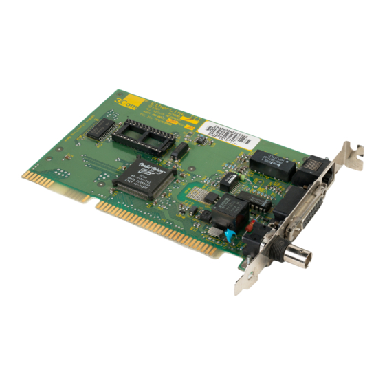
Page 24: Adapter Types
Installing the Adapter 3C509 (ISA coax) 3C509-COMBO (ISA COMBO) 3C579 (EISA coax) Figure 1-1. Adapter Types 3C09-TP (ISA TP) 3C579-TP (EISA TP) -
Page 25: Installing The Boot Prom
Installing the Boot PROM The boot PROM is optional and can be purchased separately. If you are installing it onto the adapter, follow the instructions that accompanied the boot PROM. Inserting the EtherLink III Adapter Follow these steps to insert the EtherLink III adapter in the computer slot. -
Page 26: Removing The Cover
Installing the Adapter 2. Remove the computer’s cover and choose an expansion slot, as shown in Figure 1-2. NOTE: Your computer may be physically different from the one illustrated. If you have trouble following these steps, refer to the documentation that came with your computer. -
Page 27: Removing The Backplate
3. Remove the expansion slot’s backplate, as shown in Figure 1-3. You can install the 3C509, 3C509-TP, or 3C509- COMBO adapter in any 16-bit ISA or 32-bit EISA expansion slot. You can only install the 3C579 or 3C579-TP adapter in a 32-bit EISA expansion slot. Figure 1-3. -
Page 28: Inserting The Adapter
Installing the Adapter Figure 1-4. Inserting the Adapter 5. Replace the computer’s cover. 6. Reconnect all devices and cables except the network cable. 7. Turn the computer on. Refer to Figure 1-1 and Table 1-1 (if necessary) to determine the type of adapter you have and then proceed to one of the following chapters to configure the adapter. -
Page 29: Chapter 2 Configuring The Isa Adapter
Chapter 2 Configuring the ISA Adapter This chapter explains how to configure an EtherLink III ISA adapter installed in an ISA computer. The section “Auto Installing a Single ISA Adapter for an ISA Computer and a NetWare NOS” explains how to use the ™... - Page 30 Configuring the ISA Adapter Configuring Multiple ISA Adapters for an ISA Computer Changing Software Option Settings Performing the procedures described in the section “Auto Installing a Single ISA Adapter for an ISA Computer and a NetWare NOS” accomplishes the following: Automatically configures the adapter Installs all necessary NetWare DOS ODI client software...
-
Page 31: Auto Installing A Single Isa Adapter For An Isa Computer And A Netware Nos
3C509-COMBO are ISA adapters. If you are not sure what type of adapter you have, refer to Figure 1-1 and Table 1-1. To use 3Com’s AutoLink auto installation software feature for a NetWare client, perform these steps: 1. Make sure that you have booted the computer under DOS, version 3.1 or later, and your computer... - Page 32 Configuring the ISA Adapter NOTE: To view the full text of the license agreement, press [F1]. The auto installation screen shown in Figure 2-1 appears. 5. Read the screen and press [Enter]. 6. When the main menu screen shown in Figure 2-2 appears, select NetWare DOS ODI Client and press [Enter].
-
Page 33: Auto Installation Screen
Configuring the ISA Adapter 2-5 Figure 2-1. Auto Installation Screen Figure 2-2. Main Menu... -
Page 34: Configuring A Single Isa Adapter For An Isa Computer And A Non-Netware Nos
5. The first time you use the diskette to install an adapter, a license screen appears. To accept the terms and conditions of the 3Com end-user software license agreement, type the following: NOTE: To view the full text of the license agreement, press [F1]. -
Page 35: Configuring Multiple Isa Adapters For An Isa Computer
6. Read the screen and press [Enter]. 7. When the main menu screen shown in Figure 2-2 appears, select Auto Configure 3Com ISA Adapter and press [Enter]. A message appears indicating successful configuration. Configuration is now complete. Proceed to Chapter 5, “Connecting to the Network.”... -
Page 36: Configuring The First Adapter
Configuring the ISA Adapter Configuring the First Adapter After you have started the EtherDisk diskette program, as explained in steps 1 through 5 in the previous section, follow the steps below: 1. When the main menu shown in Figure 2-2 appears, select Configuration/Diagnostic/ Troubleshooting. -
Page 37: Main Window With First Adapter Selected
Configuring the ISA Adapter 2-9 2. Highlight the adapter you want to configure by using the arrow keys. Then press [Enter], or tab to the Select item on the menu bar and press [Enter]. A screen similar to the one shown in Figure 2-4 appears, showing your selection. -
Page 38: Configuration Dialog Box
2-10 Configuring the ISA Adapter 3. The menu selection Configure Adapter appears already highlighted. Press [Enter]. A configuration screen similar to that shown in Figure 2-5 appears. Figure 2-5. Configuration Dialog Box 4. From the screen similar to the one shown in Figure 2-5, make sure the <Auto Configure>... -
Page 39: Configuring The Remaining Adapter(S)
5. The <OK> command button becomes highlighted after configuration is complete. Press [Enter] again to accept the configuration parameters. Configuring the Remaining Adapter(s) To configure the rest of the adapters, return to the Configuration and Diagnostic screen and repeat the steps in the previous section. - Page 40 2-12 Configuring the ISA Adapter Table 2-1 lists each software option, the default setting, and the available settings. Refer to the on-line help (using [F1] when the option is highlighted) for more information about each setting. Table 2-1. Option Settings Option Default Setting I/O Base Address...
- Page 41 Configuring the ISA Adapter 2-13 1. Make sure the EtherLink III adapter has been installed in your ISA computer (refer to Chapter 1 for instructions). 2. Boot your computer under DOS, version 3.1 or later. 3. Place the EtherDisk diskette in a floppy drive on your computer and make that drive the active drive.
- Page 42 2-14 Configuring the ISA Adapter 9. Press [Tab] to highlight the main dialog box, and use the arrow keys to highlight one of the parameter options. Press [Enter]. A second dialog box appears. 10. Use the arrow keys to scroll through the list of settings for that option.
-
Page 43: Chapter 3 Configuring The Eisa Adapter
Chapter 3 Configuring the EISA Adapter The EtherLink III 3C579 and 3C579-TP adapters are EISA adapters. If you are not sure what type of adapter you have, refer to Figure 1-1 and Table 1-1. This chapter first explains how to configure the EISA com- puter to accept the EISA adapter using the EISA configu- ration diskette that accompanied your computer. -
Page 44: Configuring The Eisa Computer To Accept An Eisa
Configuring the EISA Adapter This chapter consists of the following sections: Configuring the EISA Computer to Accept an EISA Adapter Changing Software Option Settings Auto Installing the EISA Adapter for a NetWare NOS Once you have configured the EISA computer to accept the adapter, you can start the auto installation procedure from the EtherDisk diskette if your network environment meets the following requirements:... - Page 45 !TCM5093.CFG for the 3C579 adapter CAUTION: An ISA adapter configured for an ISA computer will work in an EISA computer. However, 3Com recommends that it be configured for an EISA computer using the EtherDisk Configuration and Diagnostic Program before it is installed in an EISA computer.
-
Page 46: Eisa Option Settings
Configuring the EISA Adapter c. Refer to Chapter 5, “Connecting to the Network,” if you do not need to change the settings and your environment does not meet the auto installation requirements. Changing Software Option Settings The EISA configuration program automatically configures the following parameters on your EISA adapter: Slot Number Interrupt Request Level... -
Page 47: Network Driver Optimization
Configuring the EISA Adapter 3-5 Network Driver Optimization This option specifies whether to optimize the network driver ® for a DOS client, a Microsoft Windows or OS/2 client, or a server environment. Changing this option may improve network performance as well as your system’s responsive- ness. -
Page 48: Auto Installing The Eisa Adapter For A Netware Nos
Configuring the EISA Adapter If you experience compatibility problems between your adapter and another device in the system other than a modem, selecting a higher modem speed may help. Auto Installing the EISA Adapter for a NetWare NOS You can start the AutoLink auto installation procedure from the EtherDisk diskette if your network environment meets the following requirements: Your network operating system must be NetWare 2.x,... -
Page 49: Auto Installation Screen
4. The first time you use the diskette to install an adapter, a license screen appears. To accept the terms and conditions of the 3Com end-user software license agreement, type the following: NOTE: To view the full text of the license agreement, press [F1]. -
Page 50: Main Menu
Configuring the EISA Adapter 5. Read the screen and press [Enter]. 6. When the main menu screen shown in Figure 3-2 appears, select NetWare DOS ODI Client and press [Enter]. NOTE: Auto installation with configuration will take several minutes. Figure 3-2. Main Menu 7. - Page 51 Configuring the EISA Adapter 3-9 NOTE: To ensure that your computer is configured with the latest client software, ask your system administrator to configure a 3Install account on the server. Instructions for configuring a 3Install account are contained in the README.TXT file located in the \QINSTALL\SERVER directory on the EtherDisk diskette.
-
Page 52: Chapter 4 Configuring The Isa Adapter For An Eisa Computer
Configuring the ISA Adapter for an EISA Computer 4-1 Chapter 4 Configuring the ISA Adapter for an EISA Computer This chapter explains how to configure an EtherLink III ISA adapter for installation in an EISA computer. This chapter contains information under the following sections: Configuring the ISA Adapter for an EISA Computer Reconfiguring the ISA Adapter for an ISA Computer... - Page 53 5. The first time you use the diskette to install an adapter, a license screen appears. To accept the terms and conditions of the 3Com end-user software license agreement, type the following: NOTE: To view the full text of the license agreement, press [F1].
-
Page 54: Auto Installation Screen
Configuring the ISA Adapter for an EISA Computer 4-3 Figure 4-1. Auto Installation Screen Figure 4-2. Main Menu... -
Page 55: Main Window With Adapter Selected
Configuring the ISA Adapter for an EISA Computer NOTE: If this computer is an operating server, notify all users of the server to save their work and log out from the network. The Configuration and Diagnostic Program disrupts the normal operation of servers and workstations, so work that is not saved may be lost. -
Page 56: Configuration Dialog Box
Configuring the ISA Adapter for an EISA Computer 4-5 When the Configure Adapter dialog box appears, as shown in Figure 4-4, select the <Modify> command button. Figure 4-4. Configuration Dialog Box 11. Select EISA with the arrow keys and press [Enter]. -
Page 57: Reconfiguring The Isa Adapter For An Isa Computer
Configuring the ISA Adapter for an EISA Computer 15. Reboot the computer. 16. Follow the instructions that accompanied your EISA computer to run the EISA configuration program. When the program asks for .CFG files to copy, insert the EtherDisk diskette, press [Enter], and use the following files: !TCM5094.CFG for the 3C509-COMBO adapter !TCM5091.CFG for the 3C509 coax adapter... - Page 58 5. The first time you use the diskette to install an adapter, a license screen appears. To accept the terms and conditions of the 3Com end-user software license agreement, type the following: NOTE: To view the full text of the license agreement, press [F1].
- Page 59 Configuring the ISA Adapter for an EISA Computer 7. When the main menu screen shown in Figure 4-2 appears, select Configuration/Diagnostic/ Troubleshooting and press [Enter]. 8. When the Configuration and Diagnostic screen appears, select Configuration and Diagnostic Program. 9. If you have multiple adapters installed, use the arrow keys to select the adapter and press [Enter].
- Page 60 Configuring the ISA Adapter for an EISA Computer 4-9 13. Save the new configuration setting to the adapter by tabbing to <OK> and pressing [Enter]. 14. Insert the EISA system configuration utility diskette and reboot the computer. 15. Remove the adapter from the EISA computer and install it in the ISA computer, following the instructions in Chapter 1.
-
Page 61: Chapter 5 Connecting To The Network
Chapter 5 Connecting to the Network This chapter describes how to connect different types of network cables to EtherLink III adapters. This chapter contains the following sections: Types of Connectors Connecting to the On-board Transceiver Connecting to the External Transceiver Refer to the section “Changing Software Option Settings”... -
Page 62: Connecting To The On-Board Transceiver
Connecting to the Network 3C509 3C509-TP 3C579 3C579-TP Figure 5-1. Adapter Backplates Connecting to the On-board Transceiver Follow these steps to connect the appropriate cable to the EtherLink III adapter. Connecting to Thin Ethernet Cable The EtherLink III coax adapters (3C509, 3C579, and 3C509-COMBO) are factory-set to use the on-board transceiver with thin Ethernet cable. -
Page 63: Connecting Thin Ethernet Cable
Connecting to the Network 5-3 3. Connect the T connector to the adapter’s BNC connector (see Figure 5-2). a. Align the T connector’s slots with the pegs on the BNC connector. b. Push the T connector in and twist it clockwise until it stops. -
Page 64: Connecting To Twisted-Pair Cable
Connecting to the Network Connecting to Twisted-pair Cable The EtherLink III 10BASE-T adapters (3C509-TP and 3C579-TP) are factory-set to use the on-board transceiver with twisted-pair cable. NOTE: The 3C509-COMBO can also be connected to a twisted-pair cable. If you do this, make sure to change the software default to On-board TP, as explained in the section “Changing Software Option Settings”... -
Page 65: Connecting To The External Transceiver
RJ-45 port Figure 5-3. Connecting Twisted-pair Cable Connecting to the External Transceiver If you are connecting an external transceiver, make sure that the Transceiver Type option in the Configure Adapter dialog box is set to External. Refer to the section “Changing Software Option Settings”... -
Page 66: Slide Latch
Connecting to the Network To connect the AUI cable: 1. Locate the adapter’s AUI connector and move the slide latch to the closed position to lock the cable, as shown in Figure 5-4. Slide latch connector Figure 5-4. Slide Latch Closed Open... -
Page 67: Connecting The Aui Cable
Connecting to the Network 5-7 2. Connect the AUI cable to the AUI connector on the adapter, as shown in Figure 5-5. Move the slide latch to the closed position to lock the cable in place. Figure 5-5. Connecting the AUI Cable AUI connector... -
Page 68: Example Of Attaching The External Transceiver
Connecting to the Network 3. Connect the other end of the AUI cable to the external transceiver, as shown in Figure 5-6. Unshielded twisted-pair cable External transceiver AUI cable Figure 5-6. Example of Attaching the External Transceiver... -
Page 69: Chapter 6 Installing The Network Drivers
Not all of the available NOS drivers are contained on the EtherDisk diskette. Additional drivers are provided by 3Com through its bulletin board services. To obtain software driver updates and patches, use one of the bulletin board services listed in Appendix D, “Technical Support.”... -
Page 70: Installing Drivers From The Etherdisk Diskette
Installing the Network Drivers Installing Drivers from the EtherDisk Diskette The EtherDisk diskette contains files and drivers, a utility program to automatically install some drivers, and software driver directories that include NDIS and Novell drivers. If you used the AutoLink auto installation software feature for a single ISA or EISA adapter under the conditions described in Chapters 2 and 3, NetWare DOS ODI client driver installation was performed automatically,... -
Page 71: Auto Installation Screen
5. The first time you use the diskette to install an adapter, a license screen appears. To accept the terms and conditions of the 3Com end-user software license agreement, type the following: The auto installation screen shown in Figure 6-1 appears. -
Page 72: Main Menu
Installing the Network Drivers 7. When the main menu screen shown in Figure 6-2 appears, select Network Drivers and press [Enter]. Figure 6-2. Main Menu 8. Select the appropriate driver for your network operating system and follow the instructions given in the menu. -
Page 73: Netware 4.X Server Drivers
Installing the Network Drivers 6-5 NetWare 4.x Server Drivers The EtherDisk diskette contains a NetWare 4.x server driver and four NetWare Loadable Modules (NLMs) that enable the NetWare 4.x driver to be used with NetWare 3.11 software. These NLMs are: –... -
Page 74: Using Multiple Adapters In A Computer
EtherLink III adapter per computer. If You Are Running 3+Open or LAN Manager If you are running 3Com’s 3+Open Manager network operating systems and you change the I/O base address setting, you must also change the IOADDRESS line in the PROTOCOL.INI file to use the new setting. -
Page 75: Chapter 7 Performing Troubleshooting And Diagnostic Tests
Performing Troubleshooting and Diagnostic Tests 7-1 Chapter 7 Performing Troubleshooting and Diagnostic Tests This chapter explains how to isolate and solve problems with EtherLink III adapters. This chapter contains information under the following sections: Diagnostic Tests Miscellaneous Checks Technical Support Sources NOTE: Make sure that the 3C509, 3C579, 3C509-TP, 3C579-TP, or 3C509-COMBO adapter is installed in either the Industry Standard Architecture (ISA) bus or... -
Page 76: Starting The Diagnostic Program
Performing Troubleshooting and Diagnostic Tests This section contains information under the following headings: Starting the Diagnostic Program Adapter Test Setup Getting Help If a Test Fails Changing the Test Setup Group 2 and Group 3 Test Setup Group 2 Test Group 3 Test Starting the Diagnostic Program To use the EtherDisk diskette Configuration and... -
Page 77: Auto Installation Screen
Performing Troubleshooting and Diagnostic Tests 7-3 Figure 7-1. Auto Installation Screen 6. When the main menu screen shown in Figure 7-2 appears, select Configuration/Diagnostic/ Troubleshooting and press [Enter]. Figure 7-2. Main Menu... - Page 78 Performing Troubleshooting and Diagnostic Tests 7. When the Configuration and Diagnostic screen appears, select Configuration and Diagnostic Program. If you are testing multiple adapters, a screen displaying multiple adapters appears. Highlight the adapter you want to test and press [Enter]. A screen similar to the one shown in Figure 7-3 appears, showing your selection.
-
Page 79: Main Window With First Adapter Selected
Performing Troubleshooting and Diagnostic Tests 7-5 Figure 7-3. Main Window with First Adapter Selected Figure 7-4. Run Tests Dialog Box... -
Page 80: Adapter Test Setup
Performing Troubleshooting and Diagnostic Tests Adapter Test Setup The Configuration and Diagnostic Program is already set up to run the Group 1 tests. To change the test parameters, refer to the section “Changing the Test Setup” later in this chapter. To set up and run Group 2 or Group 3 tests, refer to “Group 2 and Group 3 Test Setup”... -
Page 81: Getting Help If A Test Fails
Performing Troubleshooting and Diagnostic Tests 7-7 FIFO Loopback Test This test uses the FIFO (first in/first out) loopback mode to verify the correct operation of the transmit and receive FIFO signals. Interrupt Test This test verifies that the adapter can generate interrupts to the computer. - Page 82 Performing Troubleshooting and Diagnostic Tests 1. Make sure the board is seated correctly in the slot. Remember that the EISA slot is deeper and requires firmer pressure to seat the adapter correctly. Check the adapter installation by reviewing the installation instructions in Chapter 1.
- Page 83 Performing Troubleshooting and Diagnostic Tests 7-9 6. Make sure that the settings for the adapter’s options are not the same settings used in the system or on any other adapter boards installed in the computer. 7. Install the adapter in another slot and run the diagnostic tests again.
-
Page 84: Changing The Test Setup
7-10 Performing Troubleshooting and Diagnostic Tests Changing the Test Setup To change the test parameters, follow these steps: 1. Choose Test Setup from the Test menu in the main window or use the <Test Setup> command button in the Run Tests dialog box. The Test Setup dialog box appears, as shown in Figure 7-5. - Page 85 Performing Troubleshooting and Diagnostic Tests 7-11 3. To change a setting in any field, follow these steps: a. In the Group Select box, use the arrow keys to select a test group. NOTE: For instructions on running Group 2 or Group 3 tests, refer to the next section, “Group 2 and Group 3 Test Setup.”...
-
Page 86: Group 2 And Group 3 Test Setup
3C509, 3C509-COMBO, or 3C579 adapter, you can use a coax loopback plug or connect to an inactive network. The plug can be ordered from 3Com. There are no loopback tests for TP adapters. A second computer set up as an echo server for the Group 3 test. -
Page 87: Assembling A Loopback Plug
“Connecting to the Network,” for instructions. If you do not have a loopback plug, you can order one from your authorized network supplier (3Com part number 3C537) or you can make your own. To assemble the loopback plug, connect two 50-ohm network cable terminators to a T connector, as shown in Figure 7-6. -
Page 88: Group 3 Test
Echo Server menu item under the Test menu, and select <Start> to make the computer an echo server. If you are setting up an echo server using a 3Com adapter other than an EtherLink III adapter, follow these steps. - Page 89 Performing Troubleshooting and Diagnostic Tests 7-15 3. Start the diagnostic program on the echo server. The diagnostic program that you use depends upon the adapter board that is installed in the echo server. After the system prompt of the drive containing the Configuration and Diagnostic Program, enter the name of the appropriate program from the following list: Diagnostic...
-
Page 90: Running The Group 3 Test
7-16 Performing Troubleshooting and Diagnostic Tests Running the Group 3 Test To run the Group 3 test on an EtherLink III adapter: 1. Start the EtherLink III Configuration and Diagnostic Program. 2. Select Test Setup from the Test menu. This program must be on the computer containing the adapter you want to test. -
Page 91: Link Beat Led
Performing Troubleshooting and Diagnostic Tests 7-17 Figure 7-7. Link Beat LED The link beat LED confirms that there is an active connection between the 3C509-TP or 3C579-TP adapter and the hub. NOTE: When you first install the adapter and power up the computer, the LED lights, but the link beat is inactive. -
Page 92: Software Checks
Support.” Technical Support Sources For any problems not discussed in this chapter, refer to Appendix D, “Technical Support,” for information on 3Com’s on-line technical services. 3ComFacts provides technical tips and product information. CardBoard and Ask3Com drivers, technical tips, and product information. -
Page 93: Appendix A Using The Configuration And Diagnostic Program
Using the Configuration and Diagnostic Program A-1 Appendix A Using the Configuration and Diagnostic Program This appendix explains how to use the Configuration and Diagnostic Program. It contains the following sections: Using the Menus Choosing a Menu Item Getting Help Exiting the Program Using the Command Line Figure A-1 shows the Configuration and Diagnostic... -
Page 94: Using The Menus
Using the Configuration and Diagnostic Program Using the Menus You can access the menus and command buttons by using the keyboard (function keys or speed keys) or a mouse. Using the Keyboard Table A-1 describes the keys to use with the Configuration and Diagnostic Program. -
Page 95: Using The Speed Keys
Using the Configuration and Diagnostic Program A-3 Table A-1. Definition of Keys (continued) Definition [F8] Accesses the Adapter Information dialog box. [F9] Accesses the Adapter Statistics dialog box. [F10] Accesses the Select Adapter dialog box. [Home] Moves the cursor to the first item in a list box. [PgDn] Moves the cursor down one screen. -
Page 96: Choosing A Menu Item
Using the Configuration and Diagnostic Program Choosing a Menu Item Table A-2 lists the menu items in the Configuration and Diagnostic Program. Each menu item is explained in the help screens. Press [F1], tab to the <Index> command button, and press [Enter] to see the list of help screens included in the program. -
Page 97: Using The File Options
Using the Configuration and Diagnostic Program A-5 Using the File Options The File Options are located in three separate dialog boxes under the menu items Configure Adapter, Run Tests, and Test Setup. The options are: Load: Loads a previously saved file that contains either a specific configuration setup or a test setup to be run on the installed adapter. -
Page 98: Exiting The Program
Using the Configuration and Diagnostic Program List Radio buttons Check On-screen command help Figure A-2. Sample Dialog Box Exiting the Program To exit a dialog box, press [Esc]. To exit the program, choose Exit from the Quit menu or press [F3]. Using the Command Line There are two ways to configure and test EtherLink III adapters:... - Page 99 Using the Configuration and Diagnostic Program A-7 Manually, from the root directory of the EtherDisk diskette, by typing: 3C5X9CFG [command keyword] [parameter list] where 3C5X9CFG represents the Configuration and Diagnostic Program name. Command keywords and parameters shown in brackets are optional. Table A-3 is a brief list of the command keywords and their definitions.
-
Page 100: Command Line Keywords
Using the Configuration and Diagnostic Program Command Line Keywords You can use the first two characters of any command or parameter as a shortcut. For example, 3C5X9CFG HE RU means 3C5X9CFG HELP RUN. The command keywords and parameters are not case- sensitive. -
Page 101: Appendix B Specifications
Appendix B Specifications This appendix lists the specifications for the EtherLink III adapters explained in this manual. It also contains pin assignments for the adapters’ RJ-45 connectors and Attachment Unit Interface (AUI) connectors. Adapter Card Specifications Network Interface 3C509 adapter: 3C579 adapter: 3C509-TP adapter: 3C579-TP adapter:... - Page 102 Specifications Physical Dimensions ISA Length: ISA Height: ISA COMBO Height: EISA Length: EISA Height: Environmental Operating Range Operating temperature: Humidity: Power Requirements Operating voltage: Mean Time Between Failures (hours calculated) 3C509 adapter 3C579 adapter 3C509-TP adapter 3C579-TP adapter 3C509-COMBO adapter MTBF = 205,000 6.299 inches 3.475 inches 4.2 inches...
- Page 103 Cable Requirements To remain compliant with the limits of a Class B digital device, 3Com requires that you use quality interface cables when connecting to these devices. Changes or modifications not expressly approved by 3Com could void the user’s authority to operate this equipment.
-
Page 104: B-1. Rj-45 Connector Pin Assignments
Specifications RJ-45 Connector Pin Assignments Figure B-1 shows the RJ-45 connector pin assignments. R D – R D + T D – T D + Figure B-1. RJ-45 Connector Pin Assignments AUI Connector Pin Assignments Table B-1 lists the pin assignments for the AUI (attachment unit interface) connector. -
Page 105: Appendix C Error Messages
Error Messages C-1 Appendix C Error Messages This appendix lists in alphabetical order the EtherDisk diskette on- line error messages. The text of each error message suggests possible causes of the error condition and gives the appropriate remedy in most cases. If error conditions persist, refer to Chapter 7, “Performing Troubleshooting and Diagnostic Tests.”... - Page 106 Error Messages Adapter failed while trying to read the adapter configuration stored on the adapter. Save a new configuration on the adapter. If the problem persists, swap with a known good EtherLink III, and try again. An adapter was configured for EISA mode, but the EISA configuration utility has not run yet.
- Page 107 Error Messages C-3 The adapter has been changed from EISA mode to ISA mode. To run Auto Configure in this new mode, you must first exit, and then rerun your EISA configuration utility. The adapter has been changed from ISA to EISA mode, or from EISA mode to ISA mode.
- Page 108 Error Messages The ConfigPort value xxxxx on the command line is not supported. Valid settings are 100–1E0, in increments of 10. Please try again. The selected EtherLink III can only be configured while in test mode. The diagnostic tests cannot be run from this mode. The selected interrupt request level is being used by another device installed in the computer.
- Page 109 3. Don’t use PC Turbo for Fast mode. Unable to locate the echo server. The request to locate has timed out. Make sure you have set up a second 3Com node as an echo server, and it is set up properly.
- Page 110 Use a later version of the Configuration and Diagnostic Program to take advantage of all the features on this adapter. Please obtain the latest version from your 3Com supplier. You are about to exit, but your new adapter configuration has not been saved.
-
Page 111: Appendix D Technical Support
Technical Support This appendix explains how to obtain worldwide support for 3Com adapters and software. On-line Product Support 3Com offers worldwide product support 24 hours a day, seven days a week, through automated on-line systems. CardBoard Bulletin Board Service CardBoard is 3Com’s menu-driven bulletin board service. -
Page 112: 3Comfacts Automated Fax Service
Automated Fax Service 3Com’s interactive fax service, 3ComFacts, provides data sheets, technical articles, diagrams, and troubleshooting instructions on 3Com products 24 hours a day, seven days a week. Within this service you may choose to access CardFacts for adapter information or NetFacts network system product information. -
Page 113: Ask3Com On-Line Service
Local access to 3Com’s fax system is available within the following countries using the numbers listed below: Denmark 800 17319 Finland 98 001 4444 France 05 90 81 58 Germany 0130 81 80 63 Italy 1678 99085 Netherlands 06 0228049... -
Page 114: 3Com Documentation On Cd-Rom
U.S. and Canada Call the following number to locate your local 3Com sales office: U.S. (1) (800) NET-3Com The 3Com sales office will refer you to the nearest 3Com authorized service partner. -
Page 115: Outside The U.s. And Canada
Outside the U.S. and Canada To locate a 3Com authorized service partner near you, contact your local 3Com sales office. Australia (61) 2 959 3020 Belgium/Netherlands (31) 3402 55033 Brazil 55 11 530 2318 France (33) 1 698 66800 Germany... -
Page 116: Returning Products For Repair
Technical Support Returning Products for Repair A product sent directly to 3Com for repair must first be assigned a Return Materials Authorization number (RMA). A product sent to 3Com without an RMA number will be returned to the sender unopened, at the sender’s expense. - Page 117 1-2 link beat LED, 5-4, 7-16 specifications, B-1 3C5X9.LAN file, 6-5 3C5xx.SET file, 2-14 3ComFacts, D-2 3Com sales offices, D-5 3Com Technical Support, D-1 3Install, 2-4, 3-9 3+Open, 6-6 adapter backplates, 1-3, 5-2 adapter types, 1-3, 1-4 Ask3Com, D-3...
- Page 118 Index A (continued) AutoLink auto installation software, 2-1, 2-3, 3-1, 6-2 EISA adapter in EISA computer and NetWare NOS, 3-6 single ISA adapter in ISA computer and NetWare NOS, 2-3 backplates, 1-3, 5-2 BNC connector, 1-3, 5-1, 5-2, 5-3 board types, 1-3, 1-4 boot PROM installing, 1-5 option, default, 2-12...
- Page 119 default option settings, 2-12, 3-4 diagnostic program names, 7-15 diagnostic tests, 7-1 adapter setup, 7-6 changing parameters of, 7-10 getting help, 7-7 Group 1, 7-6 Group 2, 7-12 Group 3, 7-14 starting, 7-2 dialog box, Test Setup, defined, DOS client, 2-12, 3-5 NetWare DOS ODI client, 2-1, 2-2, 2-4, 3-1, 3-6 DOS operating system, 2-3, 2-6,...
- Page 120 Index Halt on Error option, 7-4, 7-11 Help [F1], 2-12, 3-4, 4-8, A-5, A-8 after test failure, 7-7 HELP keyword, A-9 OS/2, 2-2, 2-12, 3-4 Personal Computer AT, xvi Personal System/2, xvi IEEE 802 standard, xv identifying adapter types, 1-3, 1-4 inserting the adapter, 1-5, 1-8 inspecting the adapter, 1-2 INSTALL, 2-3, 2-6, 2-13, 3-7, 4-2,...
- Page 121 N (continued) network cables connecting thick coaxial, 5-6 thin coaxial, 5-2 twisted-pair, 5-4 FCC requirements, B-3 network driver optimization, 3-5 network drivers default settings, 2-12, 3-4 installation, 6-1 NDIS, 6-2 NetWare 4.x server, 6-5 NetWare ODI client, 2-1, 2-3, 3-1, 3-6, 6-2, 6-6 network interface specification, B-1 Network Loopback Test, 7-12 NLM, 6-5...
- Page 122 Index setup EISA adapter for EISA computer, 3-2, 3-6 ISA adapter for EISA computer, 4-1 for ISA computer and NetWare NOS, 2-3 for ISA computer and non-NetWare NOS, 2-6 reconfiguring for ISA computer, 4-6 slide latch, 5-6 software options, 2-12, 3-4 specifications, adapter, B-1 speed keys, A-3 T connector, 5-2, 5-3, 7-13...
Need help?
Do you have a question about the EtherLink 3C509B and is the answer not in the manual?
Questions and answers