Table of Contents
Advertisement
Quick Links
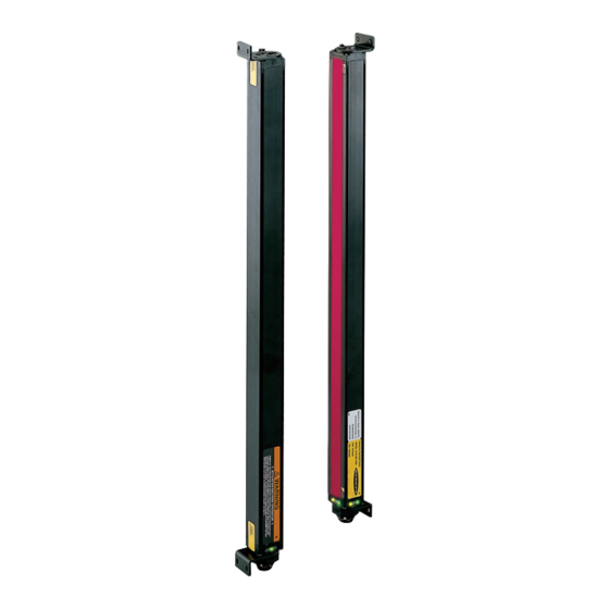
A-GAGE ® High-Resolution MINI-ARRAY ® Instruction Manual
High-Resolution MINI-ARRAY Features
• Excels at high-speed, precise process
monitoring and inspection applications
• A comprehensive combination of scanning
modes and outputs:
– 10 measurement ("Scan Analysis") modes
– 3 scanning methods
– Beam blanking
– Selectable continuous, gated or host-
controlled scan initiation
– Programmable hysteresis for high and low
limits
– Serial communication options
• Storable scanning programs eliminate
reprogramming for repeated applications
• Non-volatile memory stores alignment
settings
• All models with both Analog and Discrete
outputs
• Analog output Null setting
• Low cost, compared with similar systems
• Precision sensors have a 380 mm to 1.8 m
(15" to 6') working range
• Wide field of view, easily aligned
• Alignment routine equalizes gain of each
beam for reliable 2.5 mm (0.10") object
detection throughout the array
• Host computer or PLC may be used to initiate
scans and/or process scan data
• Unique addresses for up to 15 control
modules on one EIA-485 Party Line
9714 10th Avenue North • Minneapolis, MN 55441
Phone: 763.544.3164 • Fax: 763.544.3213
Email: sensors@baneng.com
Printed.in.USA.
For controllers with 2 analog and 2 discrete outputs
¤
04/12
¤
!
WARNING . . .
Not To Be Used for Personnel Protection
These sensors do NOT include the self-checking redundant
circuitry necessary to allow their use in personnel safety applications. A
sensor failure or malfunction can cause either an energized or de-energized
output condition. Consult your current Banner Safety Products catalog for
safety products which meet OSHA, ANSI and IEC standards for personnel
protection.
P/N 64118 rev.C
Advertisement
Table of Contents

Related Manuals for Banner A-GAGE High-Resolution MINI-ARRAY MAHE6A


Summary of Contents for Banner A-GAGE High-Resolution MINI-ARRAY MAHE6A
- Page 1 A ¤ sensor failure or malfunction can cause either an energized or de-energized output condition. Consult your current Banner Safety Products catalog for safety products which meet OSHA, ANSI and IEC standards for personnel protection.
- Page 2 Banner Engineering Corp. Minneapolis, U.S.A. • www.bannerengineering.com • Tel: 763.544.3164 P/N 64118 rev. B...
-
Page 3: Table Of Contents
Appendix B: Glossary ......... . 38 Banner Engineering Corp. -
Page 4: System Description
380 mm to 1.8 m (15" to 6'). Each of the four versatile microcontroller-based control modules are configured using a PC-compatible computer running Windows XP, Vista, or 7, and the supplied software, via the built-in RS-232 interface. Banner Engineering Corp. Minneapolis, U.S.A. • www.bannerengineering.com • Tel: 763.544.3164... - Page 5 MAHCIN-1 2 NPN (2) 4-20 mA Sinking Communication Cables MASC 2 m (6.5') DB9, straight RS-232 cable Figure 1-1. A-GAGE High-Resolution MINI-ARRAY System components Banner Engineering Corp. Banner Engineering Corp. Minneapolis, U.S.A. Minneapolis, U.S.A. • • www.bannerengineering.com • Tel: 763.544.3164 www.bannerengineering.com •...
-
Page 6: System Features
Red Discrete Output #1 LED Red Alarm (Discrete Output #2) LED Red Gate LED Green Align LED RS-232 Port Figure 1-2. A-GAGE High-Resolution MINI-ARRAY System features Banner Engineering Corp. Minneapolis, U.S.A. • www.bannerengineering.com • Tel: 763.544.3164 P/N 64118 rev. B... -
Page 7: Typical Applications
1.3 Typical Applications Log Profiling for Lumber Optimization Box Profiling Maintaining Centering of Opaque Rolled Goods Inspection Applications Figure 1-3. Typical applications for the A-GAGE High-Resolution MINI-ARRAY System Banner Engineering Corp. Banner Engineering Corp. Minneapolis, U.S.A. Minneapolis, U.S.A. • •... -
Page 8: Specifications
Sensors connect to controller using two 5-conductor quick-disconnect cables (one each for emitter and receiver), ordered separately. See page 5 for available lengths. Use only Banner cables, which incorporate a “twisted pair” for noise immunity. Cables measure 8.1 mm (0.32") in diameter and are shielded and PVC-jacketed. - Page 9 1897 mm (74.7") 1840 mm (72.4") MAHR70A Receiver MAHE77A Emitter 2028 mm (79.8") 2060 mm (81.1") 2003 mm (78.8") MAHR77A Receiver Banner Engineering Corp. Banner Engineering Corp. Minneapolis, U.S.A. Minneapolis, U.S.A. • • www.bannerengineering.com • Tel: 763.544.3164 www.bannerengineering.com • Tel: 763.544.3164...
-
Page 10: Control Module Specifications
Control Module: NEMA 1, IEC IP20 Emitter/Receiver: NEMA 4, 13; IEC IP65 Operating Conditions Temperature: 0° to +50°C (+32° to 122°F) Maximum relative humidity: 95% @ 50°C (non-condensing) Certifications Banner Engineering Corp. Minneapolis, U.S.A. • www.bannerengineering.com • Tel: 763.544.3164 P/N 64118 rev. B... - Page 11 69.0 mm DIN mounting slot (2.72 ") 5.5 mm Slot for M3.5 screws (2) (0.22") Figure 2-2. Control module dimensions Banner Engineering Corp. Banner Engineering Corp. Minneapolis, U.S.A. Minneapolis, U.S.A. • • www.bannerengineering.com • Tel: 763.544.3164 www.bannerengineering.com • Tel: 763.544.3164...
-
Page 12: Installation And Mechanical Alignment
3. Installation and Mechanical Alignment 3.1 Emitter and Receiver Mounting Banner MINI-ARRAY emitters and receivers are small, lightweight, and easy to handle during mounting. The mounting brackets (supplied) allow ±30° rotation. From a common point of reference, make measurements to locate the emitter and receiver in the same plane with their midpoints directly opposite each other. -
Page 13: Control Module Mounting
Mounting dimensions for the controller are shown in Figure 2-2, on page 11. The control module is supplied with M3.5 hardware for direct mounting to a surface, or the module may be mounted onto standard 35 mm DIN rail. Banner Engineering Corp. Banner Engineering Corp. Minneapolis, U.S.A. -
Page 14: Hookups
4-20 mA OUTPUT#2 (ALARM) ANALOG ANALOG OUTPUT #2 OUTPUT #1 150 mA Load Load +16 – 30V dc +16 – 30V dc Figure 3-6. MAHCIP-1 hookup Banner Engineering Corp. Minneapolis, U.S.A. • www.bannerengineering.com • Tel: 763.544.3164 P/N 64118 rev. B... -
Page 15: Emitter And Receiver Hookups
DB-9 connector with connections as shown in Figure 3-8. NOTE: DO NOT use a “null modem” RS-232 cable RS-485: RS-485 serial port is located at terminals #18 (TX) and #19 (TX). Banner Engineering Corp. Banner Engineering Corp. Minneapolis, U.S.A. -
Page 16: Software Installation
After the software is installed, a MINI-ARRAY shortcut icon is placed on your desktop. Double-click on the MINI-ARRAY icon to launch the program, then follow the configuration and setup procedures described in Section 5 of the primary manual. Figure 4-1. MINI-ARRAY software installation: dialog boxes Banner Engineering Corp. Minneapolis, U.S.A. •... -
Page 17: Control Module Configuration
5. Control Module Configuration The A-GAGE High-Resolution MINI-ARRAY control module is easily configured using a Windows ® menu-style routine; the configuration routine requires the Banner-supplied HRMA software and a PC-compatible computer (running Windows ® XP, Vista, or 7) A serial data connection is made between the computer and the DB9 connector on the control module. -
Page 18: Factory Settings
The system is now ready for operation and does not require re-alignment unless the emitter or receiver is moved. Banner Engineering Corp. Minneapolis, U.S.A. • www.bannerengineering.com • Tel: 763.544.3164... -
Page 19: Software Alignment Routine
Blanking specifications can be saved and read from a computer file using the Save To File and Read From File commands. Banner Engineering Corp. Banner Engineering Corp. Minneapolis, U.S.A. -
Page 20: Blanking
Scanning Mode Limitations for Blanking: All blanking features are available with Continuous Scan mode. For single-and double- edge scan, blanking is limited to four blanking fields. Other blanking features are ignored. Banner Engineering Corp. Minneapolis, U.S.A. • www.bannerengineering.com • Tel: 763.544.3164... -
Page 21: Programming Control Module Response
(see section 5.4.5). Once configured, a PSF may be sent to the control module via the Send PSF command. Likewise, the PSF currently loaded into the control module may be displayed by using the Upload PSF command. Banner Engineering Corp. Banner Engineering Corp. Minneapolis, U.S.A. - Page 22 Output #2 whenever the System detects a sensing error or if the optical signal becomes marginal. Figure 5-9. Use the PSF Configuration screen to program each control module individually Banner Engineering Corp. Minneapolis, U.S.A. • www.bannerengineering.com • Tel: 763.544.3164...
-
Page 23: Selected Controller And Serial Connection
• Gate ON/OFF: the control module will scan once for each gate transition from ON to OFF. • Gate OFF/ON: the control module will scan once for each gate transition from OFF to ON. Banner Engineering Corp. Banner Engineering Corp. -
Page 24: Scanning Method
Step #5 Step #6 Step #7 Beam #40 Beam #44 Beam #42 Beam #43 Blocked Clear Blocked Blocked Figure 5-13. Finding an edge using a binary search Banner Engineering Corp. Minneapolis, U.S.A. • www.bannerengineering.com • Tel: 763.544.3164 P/N 64118 rev. B... - Page 25 1951 mm 58.4 41.9 21.9 12.1 (76.8") Figure 5-15. The effect of sensor length and scanning method on scan time (typical) Banner Engineering Corp. Banner Engineering Corp. Minneapolis, U.S.A. Minneapolis, U.S.A. • • www.bannerengineering.com • Tel: 763.544.3164 www.bannerengineering.com • Tel: 763.544.3164...
-
Page 26: Scan Analysis Mode Selection
Figure 5-18. Assigning an Analysis Mode to the Null value. each Analog Output (PSF Configuration screen) Banner Engineering Corp. Minneapolis, U.S.A. • www.bannerengineering.com • Tel: 763.544.3164 P/N 64118 rev. B... -
Page 27: Zero Value
Output holds the last non-zero value before the light screen became clear. NULL: Provides the minimum value Figure 5-21. Zero Value (PSF Configuration SPAN: Provides the maximum value. screen) Banner Engineering Corp. Banner Engineering Corp. Minneapolis, U.S.A. Minneapolis, U.S.A. • • www.bannerengineering.com • Tel: 763.544.3164 www.bannerengineering.com •... -
Page 28: Discrete Output Configuration (Analysis Mode Assignment)
Trigger pulse will come at the end of the scan (Trigger Channel Number will be ignored). Figure 5-24. Trigger Channel Banner Engineering Corp. Minneapolis, U.S.A. • www.bannerengineering.com • Tel: 763.544.3164... -
Page 29: Serial Communication With A Host Controller
For more information on the data formats, refer to Appendix Figure 5-25. Serial Data Transmission options (PSF Configuration screen) Banner Engineering Corp. Banner Engineering Corp. Minneapolis, U.S.A. Minneapolis, U.S.A. •... -
Page 30: Serial Options
To check the values of the PSF currently loaded into the control module, select Upload PSF. The current PSF will be displayed on the PSF Configuration screen. Figure 5-26. PSF Output options (PSF Configuration screen) Banner Engineering Corp. Banner Engineering Corp. Minneapolis, U.S.A. -
Page 31: Saving And Recalling Psf Files
Window; the present PSF Screen values are not retained. The Exit command is similar to the Quit command, except the user will be prompted to save the configuration values to a parameter setup file (PSF). Banner Engineering Corp. Banner Engineering Corp. Minneapolis, U.S.A. -
Page 32: System Diagnostics
This indicator is ON when either the green or both the green and yellow LEDs Figure 6-2. Key to System Diagnostics of the receiver are ON. Indicator codes Banner Engineering Corp. Minneapolis, U.S.A. • www.bannerengineering.com • Tel: 763.544.3164 P/N 64118 rev. B... -
Page 33: Diagnostics Routine
The Diagnostics routine also displays the part number and date code of the controller, information that may be useful if factory- Figure 6-3. Diagnostics screen, accessible from the MINI- assisted troubleshooting by telephone is required. ARRAY menu Banner Engineering Corp. Banner Engineering Corp. Minneapolis, U.S.A. Minneapolis, U.S.A. •... -
Page 34: Appendix A: Data Transmission
At the end of the string, the control module will place a termination byte. The termination bye is the ASCII character for a linefeed (hex value 0A). These three bytes collectively are called the Serial Header string. Banner Engineering Corp. Minneapolis, U.S.A. •... -
Page 35: Ascii Format Data Transmission
Figure A-3. Binary data values This string would have the start byte, controller ID, followed by the eight data bytes and terminated with the 0x0A. The header bytes may be suppressed if necessary. Banner Engineering Corp. Banner Engineering Corp. Minneapolis, U.S.A. -
Page 36: Max Measure Mode Command String
If the sensor is presently scanning an object when the message is sent, the control module will give the maximum values for the present object. Banner Engineering Corp. Minneapolis, U.S.A. • www.bannerengineering.com • Tel: 763.544.3164... - Page 37 Banner Engineering Corp. Banner Engineering Corp. Minneapolis, U.S.A. Minneapolis, U.S.A. • • www.bannerengineering.com • Tel: 763.544.3164 www.bannerengineering.com • Tel: 763.544.3164 P/N 64118 rev. B...
-
Page 38: Appendix B: Glossary
Made Beam: A beam that runs unobstructed from the emitter to the receiver (same as an unblocked or clear beam). Unblocked Beam: A beam that runs unobstructed from the emitter to the receiver (same as a made or clear beam). Banner Engineering Corp. Minneapolis, U.S.A. • www.bannerengineering.com • Tel: 763.544.3164... - Page 39 Banner Engineering Corp. Banner Engineering Corp. Minneapolis, U.S.A. Minneapolis, U.S.A. • • www.bannerengineering.com • Tel: 763.544.3164 www.bannerengineering.com • Tel: 763.544.3164 P/N 64118 rev. B...
- Page 40 Banner Engineering Corp Limited Warranty Banner Engineering Corp. warrants its products to be free from defects in material and workmanship for one year following the date of shipment. Banner Engineering Corp. will repair or replace, free of charge, any product of its manufacture which, at the time it is returned to the factory, is found to have been defective during the warranty period.
Need help?
Do you have a question about the A-GAGE High-Resolution MINI-ARRAY MAHE6A and is the answer not in the manual?
Questions and answers