
Related Manuals for Banner A-GAGE MINI-ARRAY MAC-1


Summary of Contents for Banner A-GAGE MINI-ARRAY MAC-1
- Page 1 ® ® A-GAGE MINI-ARRAY Measuring Light Screen System Instruction Manual Original Instructions 43298 Rev. G 21 April 2017 © Banner Engineering Corp. All rights reserved 43298...
-
Page 2: Table Of Contents
7.1 Host Mode Command ..................................28 7.2 Serial Data Format ....................................28 7.3 ASCII Format Data Transmission ................................. 28 7.4 Binary Format Data Transmission ............................... 29 8 Accessories ..................................30 8.1 Anti-Vibration Mounting Kits ................................30 9 Banner Engineering Corp. Limited Warranty ........................31... -
Page 3: Features
Controller is programmable for any one or two of ten measurement modes (depending ® on model) and any one of four scanning modes, using a computer running Windows Vista, or 7, and the Banner-supplied software • Software is also supplied for display of error analysis (via controller self-diagnostics) and for sensor alignment •... - Page 4 ® ® A-GAGE MINI-ARRAY Measuring Light Screen System Emitter/Receiver Pairs -- 19.1 mm (3/4 inch) Beam Spacing (16 beams/foot) Emitter Receiver Array Length Total Beams BMEL616A BMRL616A 133 mm (5.25 inch) BMEL1216A BMRL1216A 286 mm (11.25 inch) BMEL1816A BMRL1816A 438 mm (17.25 inch) BMEL2416A BMRL2416A 591 mm (23.25 inch)
-
Page 5: Overview
Measuring Light Screen System 2 Overview ® The Banner A-GAGE MINI-ARRAY measuring light screen is ideal for applications such as on-the-fly product sizing and profiling, edge- guiding and center-guiding, loop tensioning control, hole detection, parts counting, die ejection verification, and similar uses. -
Page 6: System Features
® ® A-GAGE MINI-ARRAY Measuring Light Screen System 2.1 System Features Built-in features simplify the operation of the A-GAGE MINI-ARRAY system. Programmable beam blanking accommodates machine components or other fixtures that must remain in or move through the light screen. Blanking is set by using the included configuration software. -
Page 7: Specifications
Cables measure 8.1 mm (0.32 in ) dia., and are shielded and PVC-jacketed; Environmental Rating conductors are 20-gauge. NEMA 4, 13 (IEC IP65) Use only Banner cables, which incorporate a "“twisted pair” for noise immunity on RS-485 data communication lines. Operating Conditions Emitter and receiver cables may not exceed 250 ft each. -
Page 8: Specifications For The Mac Controllers
Via RS-232 to PC-compatible computer running Windows ® operating system GATE input: Optically-isolated, requires 10 to 30 V dc (7.5K input impedance) and using Banner-supplied software for gate signal Discrete Outputs (MAC-1) Analog Outputs Output 1 (OUT 1): Reed relay contact rated 125 V ac/dc max., 10 VA max. -
Page 9: Dimensions For The Controller
® ® A-GAGE MINI-ARRAY Measuring Light Screen System Sensor Scan Time Required Overcurrent Protection For all models: 55 microseconds per beam plus processing time. The processing time is dependent on the scan analysis and the number of active outputs. This WARNING: Electrical connections must be made by timing assumes a straight scan, continuous, and TBB mode. -
Page 10: Installation Instructions
M4 bolts to dampen impulse forces and prevent possible damage from resonant vibration of the emitter or Mounting receiver assembly. Two different Anti-Vibration Surface Mounting Kits are available from Banner. See Accessories on page 30. Mounting Bracket Nut (4) Torque to 12 in. -
Page 11: Controller Mounting
® ® A-GAGE MINI-ARRAY Measuring Light Screen System Trim foil shield flush with cable Uninsulated drain wire Figure 3. Emitter/Receiver Cable Preparation 7. Connect the shielded cables to the emitter and receiver. Follow the local wiring code for low-voltage dc control cables. The same cable type is used for both emitter and receiver (two cables required per system). -
Page 12: Macp-1 Controller Wiring
® ® A-GAGE MINI-ARRAY Measuring Light Screen System Power V– – – 500 mA 16–30 V dc Max. RS-485 10–30 V dc 30 V 1.2 A Max. Out 1 Gate 150 mA EMITTER and Max. RECEIVER CABLES ALARM 4.4.2 MACP-1 Controller Wiring Output 1: Controller terminal #9 (OUT1) is an open-collector PNP transistor switch rated at 30V dc max., 150 mA max. -
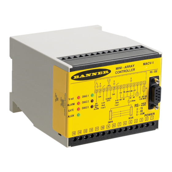
Page 13: Macv-1 Controller Wiring
® ® A-GAGE MINI-ARRAY Measuring Light Screen System Power – – Out 1 RS485 10–30 V dc 16–30 V dc 30 V 30 V Gate 1.2 A Max. 150 mA EMITTER and 150 mA Max. RECEIVER CABLES Max. ALARM 4.4.4 MACV-1 Controller Wiring Voltage outputs 1 and 2: Controller terminals #9 (V out 1) and #13 (V out 2) are analog voltage outputs. -
Page 14: Mac16P-1 Controller Wiring
® ® A-GAGE MINI-ARRAY Measuring Light Screen System Power – 10–30 V dc Gate 16–30 V dc 4–20 mA 4–20 mA 30 V I out 2 I out 1 1.2 A Max. 150 mA EMITTER and Max. RECEIVER CABLES ALARM 4.4.6 MAC16P-1 Controller Wiring Terminals #15 through #30 are open-collector PNP transistor outputs rated at 30 V dc maximum, 150 mA maximum. -
Page 15: System Power Wiring
® ® A-GAGE MINI-ARRAY Measuring Light Screen System Power – 16–30 V dc 10–30 V dc 1.2 A Max. EMITTER and Gate RECEIVER CABLES 16 Solid-state Ouputs through 150 mA Max each 4.5 System Power Wiring Wire the system power. 1. -
Page 16: Configuration Instructions
® ® A-GAGE MINI-ARRAY Measuring Light Screen System 5 Configuration Instructions 5.1 Install the Software The Parameter Setup Software CD includes an installation program that quickly and easily loads the MINI-ARRAY configuration program into the computer. The MINI-ARRAY configuration program requires approximately 50 MB of hard disk space. Install as follows: 1. - Page 17 ® ® A-GAGE MINI-ARRAY Measuring Light Screen System PSF Configuration Screen for Models MAC-1, MACP-1, MACN-1, PSF Configuration Screen for Models MAC16N-1 and MAC16P-1 MACV-1, and MACI-1 The software included with the controller makes it easy to configure the MINI-ARRAY using your PC-compatible computer. Simply install the software, launch the program, and access the Edit PSF Configuration screen.
-
Page 18: Assigning The Analysis Mode
Banner-supplied software via the built-in RS-232 or RS-485 interface. You may program one or two Measurement Analysis modes. Assign Meas1 or Meas2 to one or both outputs. The Banner MINI-ARRAY System can be programmed for any one or two of the following Scan Analysis Modes: All Data (ALL)—The controller passes all beam condition data for every scan to the serial interface for analysis by a host computer or... -
Page 19: Configuring The Outputs
® ® A-GAGE MINI-ARRAY Measuring Light Screen System Last Beam Made, First Beam Made Total Beams Made, Total Beams Blocked Last Beam Blocked, First Beam Blocked BMRL 3616A BMRL 3616A BMRL 3616A Receiver Receiver Receiver BMEL 3616A BMEL 3616A BMEL 3616A Emitter Emitter Emitter... - Page 20 ® ® A-GAGE MINI-ARRAY Measuring Light Screen System Configuring the Discrete Outputs (MAC16P-1, MAC16N-1) Configure the 16 discrete outputs using the Outputs button on the Multiple Output MINI-ARRAY PSF Configuration screen. The Outputs button launches the Edit Discrete Outputs screen, which allows the Set Points and Hysteresis levels to be defined for each output.
-
Page 21: Configuring The Blanking Specifications
® ® A-GAGE MINI-ARRAY Measuring Light Screen System Null Span Model MACV-1 10 mV 2.3 V 4.8 V 10.1 V MACI-1 3.9 mA 7.8 mA 11.9 mA 20.2 mA Each output’s Null and Span is independently adjusted using the sliding bars. When the adjustments are made, the new values can be temporarily monitored by selecting either the Null Update or Span Update button. -
Page 22: Configuring The Scanning Method
® ® A-GAGE MINI-ARRAY Measuring Light Screen System 5.4.4 Configuring the Scanning Method The control module may be configured for one of four available scanning methods: straight, interlaced, edge, or skip. Straight Scan is the default mode in which all beams are scanned in sequence from the bottom end (cable end) to the top end of the sensors. -
Page 23: Psf Assignment And Storage
® ® A-GAGE MINI-ARRAY Measuring Light Screen System The selectable communication baud rates are 9600, 12000, and 38400. The communication protocol is one start bit, one stop bit, 8 data bits, and even parity. When RS-485 communication is used, each controller module may be assigned a controller ID. Select letter A through O for individual identification of up to 15 Controllers on a RS-485 “party line.”... - Page 24 ® ® A-GAGE MINI-ARRAY Measuring Light Screen System 3. Select one of the following options. • Select Stop to freeze the data. • Select Step to initiate a single scan of the array. This simulates a “snapshot” of what is viewed by the array when Step is selected.
-
Page 25: Operating Instructions
® ® A-GAGE MINI-ARRAY Measuring Light Screen System 6 Operating Instructions 6.1 Status Indicators for the MINI-ARRAY Sensors Note: Status indicators appear to “freeze” if the controller has been configured for the Gate or the Host Mode and there is no signal to cause a scan update. -
Page 26: Diagnostics Program
® ® A-GAGE MINI-ARRAY Measuring Light Screen System Indicator LED Color Function Indicates proper sensor alignment and a clear light screen; this indicator is ON when the green or green and Align Green yellow LEDs of the receiver are ON System Status Diag Normal... - Page 27 ® ® A-GAGE MINI-ARRAY Measuring Light Screen System The Diagnostics screen displays the type of each emitter and receiver module (Board) and its functional status (State). If an error has occurred, the specific problem beam (Channel) will be identified. Additionally, if there is a problem with an emitter or receiver cable connection, a “No Response”...
-
Page 28: Additional Information
® ® A-GAGE MINI-ARRAY Measuring Light Screen System 7 Additional Information 7.1 Host Mode Command The MINI-ARRAY controller can communicate with a computer or PLC via either an RS-232 connection (all models) or RS-485 connection (discrete-output models). The host can respond to output from the controller when the controller is programmed for either the Continuous or Gate control mode. -
Page 29: Binary Format Data Transmission
® ® A-GAGE MINI-ARRAY Measuring Light Screen System Definitions for ASCII Data Values For the ALL Measurement Mode Character Ch 4 Ch 3 Ch 2 Ch 1 7.4 Binary Format Data Transmission There are two binary formats. The one used depends upon which Channel Status Binary Code... -
Page 30: Accessories
® ® A-GAGE MINI-ARRAY Measuring Light Screen System 8 Accessories 8.1 Anti-Vibration Mounting Kits MSVM-1 MAVM-1 • 4 anti-vibration mounts (M4 x 0.7 x 9.5 mm) • 4 anti-vibration mounts (M4 x 0.7 x 9.5 mm) • 8 M4 Keps nuts •... -
Page 31: Banner Engineering Corp. Limited Warranty
MERCHANTABILITY OR FITNESS FOR A PARTICULAR PURPOSE), AND WHETHER ARISING UNDER COURSE OF PERFORMANCE, COURSE OF DEALING OR TRADE USAGE. This Warranty is exclusive and limited to repair or, at the discretion of Banner Engineering Corp., replacement. IN NO EVENT SHALL BANNER ENGINEERING CORP. BE LIABLE TO BUYER OR ANY OTHER PERSON OR ENTITY FOR ANY EXTRA COSTS, EXPENSES, LOSSES, LOSS OF PROFITS, OR ANY INCIDENTAL, CONSEQUENTIAL OR SPECIAL DAMAGES RESULTING FROM ANY PRODUCT DEFECT OR FROM THE USE OR INABILITY TO USE THE PRODUCT, WHETHER ARISING IN CONTRACT OR WARRANTY, STATUTE, TORT, STRICT LIABILITY, NEGLIGENCE, OR OTHERWISE.
Need help?
Do you have a question about the A-GAGE MINI-ARRAY MAC-1 and is the answer not in the manual?
Questions and answers