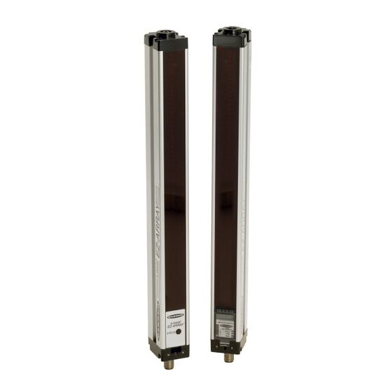
Banner A-GAGE EZ-ARRAY Instruction Manual
Two-piece sensing array with 2 analog and 2 discrete outputs, plus serial output
Hide thumbs
Also See for A-GAGE EZ-ARRAY:
- Instruction manual (33 pages) ,
- Instruction manual (42 pages)
Table of Contents
Advertisement
Quick Links
A-GAGE
Two-piece sensing array with 2 analog and 2 discrete outputs, plus serial output
•
A cost-effective, two-piece measuring light curtain designed for
quick and simple installations with the sophistication to handle
the toughest sensing applications
•
Excels at high-speed, precise process monitoring and inspection,
profiling, and web-guiding applications
•
A comprehensive combination of scanning options:
– 14 measurement ("scan analysis") modes
– 3 scanning methods
– Selectable beam blanking
– Selectable continuous or gated scan initiation
– Selectable threshold setting for semi-transparent applications
– 2 analog outputs, 2 discrete outputs, plus Modbus 485-RTU
serial output
•
Outstanding 4 meter range with 5 mm beam spacing
•
Available in 12 lengths from 150 mm to 2400 mm
•
Excellent 5 mm minimum object detection or 2.5 mm edge
resolution, depending on scanning method
•
Receiver user interface for quick, intuitive setup of many common
applications:
– 6-position DIP switch for setting scan mode, measurement
mode, analog slope, discrete output 2 option (complementary
measurement or alarm operation)
– 2 push buttons for gain method selection and alignment/
blanking
– 7 Zone LEDs for instant alignment and beam blockage
information
– 3-digit display for sensing information and diagnostics
•
Software PC interface available for advanced configuration setup
•
Remote teach wire option for alignment, gain settings, inverted
display, and DIP switch disable
WARNING . . .
Not To Be Used for Personnel Protection
Never use these products as sensing devices for personnel protection. Doing so could lead to serious injury or death.
These sensors do NOT include the self-checking redundant circuitry necessary to allow their use in personnel safety applications. A
sensor failure or malfunction can cause either an energized or de-energized sensor output condition. Consult your current Banner
Safety Products catalog for safety products which meet OSHA, ANSI and IEC standards for personnel protection.
Printed in USA
EZ-ARRAY
®
Features
Instruction Manual
™
01/16
P/N 130426 Rev. D
Advertisement
Table of Contents
Troubleshooting

Related Manuals for Banner A-GAGE EZ-ARRAY


Summary of Contents for Banner A-GAGE EZ-ARRAY
- Page 1 These sensors do NOT include the self-checking redundant circuitry necessary to allow their use in personnel safety applications. A sensor failure or malfunction can cause either an energized or de-energized sensor output condition. Consult your current Banner Safety Products catalog for safety products which meet OSHA, ANSI and IEC standards for personnel protection.
-
Page 2: Table Of Contents
4.5 Troubleshooting and Error Codes ....22 5. Using the PC Interface (Banner Sensors GUI)..23 5.1 Supplied Software . -
Page 3: Overview
5 mm in diameter or measuring part edges within 2.5 mm, depending on the scanning method A typical A-GAGE EZ-ARRAY has four components: an emitter selected (see Section 1.6). The sensing range is 400 mm to 4 m and a receiver, each with an integral quick-disconnect (QD) (16"... -
Page 4: Features
Section 4.5 for display codes and troubleshooting. For more advanced, individualized applications, use the supplied PC interface software program (the “Banner Sensors GUI”; The Alignment routine (Section 4.2 or Section 5.6) automatically Section 5) to configure the receiver. The menu-driven program equalizes the excess gain of each beam for reliable object easily accesses the many scanning and output options. -
Page 5: Status Indicators
A-GAGE EZ-ARRAY Overview Instruction Manual into seven equal segments, each of which is represented by sensors and a PC is accomplished via the serial output and one of the seven LEDs. The LED closest to DIP switch S6 (see Modbus RTU-485 interface. -
Page 6: Receiver Gray (Remote Teach) Wire
A-GAGE EZ-ARRAY Overview Instruction Manual Receiver Interface Status Indicators 1.5 Receiver Gray (Remote Teach) Wire The receiver has three status indicators: green/red System Status, yellow Modbus Activity, and red Modbus Error. The The receiver gray (remote teach) wire is used to electronically following table lists the indicator states. -
Page 7: Scanning Method
A-GAGE EZ-ARRAY Overview Instruction Manual When the gray wire is disabled, the receiver is in continuous Straight Scan is the default mode, in which all beams are scan mode; it begins a new scan immediately after updating scanned in sequence, from the display end to the far end the outputs from the previous scan. - Page 8 A-GAGE EZ-ARRAY Overview Instruction Manual Double-Edge Scan is used to detect two edges of a single 5. When the bottom edge is found, the sensor continues to step object, for example, to determine box width measurements. through the array until it finds the next unblocked beam.
-
Page 9: Gain Configuration
A-GAGE EZ-ARRAY Overview Instruction Manual Maximum Scan Times (in milliseconds) Double-Edge Scan Straight Single-Edge Array Length Step Step Step Step Step Step Scan Scan 1 Beam 2 Beams 4 Beams 8 Beams 16 Beams 32 Beams 150 mm (5.9") 300 mm (11.8") 450 mm (17.7") -
Page 10: Electronic Alignment Routine
A-GAGE EZ-ARRAY Overview Instruction Manual “Beam Location” Modes 1.8 Electronic Alignment Routine • First Beam Blocked (FBB): The location of the first blocked beam. The objective of the optical alignment process is to adjust the • First Beam Made (FBM): The location of the first made emitter light level to maximize sensor performance. -
Page 11: Analog Output Configuration
A-GAGE EZ-ARRAY Overview Instruction Manual • Transitions (TRN): The number of changes from blocked to 1.12 Discrete Output Configuration clear status and from clear to blocked status. (If beams 6-34 are blocked, then there is a clear-to-blocked transition from Discrete Output 1; Receiver Interface... -
Page 12: Components And Specifications
Components and Specifications A-GAGE EZ-ARRAY Instruction Manual 2. Components and Specifications 2.1 Sensor Models Emitter Receiver Array Emitter/Receiver Model Emitter/Receiver Model Total Analog Output Length NPN Outputs PNP Outputs Beams EA5E150Q Emitter EA5E150Q Emitter – 150 mm EA5R150NIXMODQ Receiver EA5R150PIXMODQ Receiver Current (4–20 mA) -
Page 13: Cordsets And Connections
A-GAGE EZ-ARRAY Components and Specifications Instruction Manual 2.2 Cordsets and Connections Quick-Disconnect Sensor Cordsets Model Description Pinout Female Connector Shown MAQDC-815 5 m (15') long M12X1 Straight female Green Brown Ø15.0 mm Yellow MAQDC-830 connector, 9 m (30') long (0.59") -
Page 14: Accessory Mounting Brackets And Stands
Components and Specifications A-GAGE EZ-ARRAY Instruction Manual 2.4 Accessory Mounting Brackets and Stands See Section 2.5 for standard brackets. Order one EZA-MBK-20 bracket per sensor, two per pair. 50.0 mm EZA-MBK-20 (1.97") 44.4 mm (1.75") Model Description 20 mm (0.79") 4.2 mm... -
Page 15: Specifications, Continued
A-GAGE EZ-ARRAY Components and Specifications Instruction Manual 2.6 Specifications, continued Supply Voltage (Limit Values) Emitter: 12 to 30V dc Receiver Analog Current Models: 12 to 30V dc Receiver Analog Voltage Models: 15 to 30V dc Supply Power Requirements Emitter/Receiver Pair (Exclusive of Discrete Load): Less than 9 watts... -
Page 16: Emitter And Receiver Dimensions
Components and Specifications A-GAGE EZ-ARRAY Instruction Manual 2.7 Emitter and Receiver Dimensions With mounting bracket flanges “out” With mounting bracket flanges “in” 36.0 mm (1.42") 45.2 mm 12 mm (1.78") (0.47") 56.0 mm (2.20") 4.2 mm (0.17") R13 mm (0.5") -
Page 17: Standard Bracket Dimensions
A-GAGE EZ-ARRAY Components and Specifications Instruction Manual 2.8 Standard Bracket Dimensions End Cap Brackets Center Bracket (model EZA-MBK-11*) (model EZA-MBK-12**) 4 x 5.8 mm (0.23") wide slots 20 mm 4 x R 19.4 mm Ø 21.5 mm (0.79") (0.76") (0.85") 55 mm Ø... -
Page 18: Installation And Alignment
Bracket Clamp NOTE: Sensor brackets are designed to mount directly to accessory MSA series stands (Section 2.3), using hardware supplied with the stands. Figure 3-1. A-GAGE EZ-ARRAY emitter and receiver mounting hardware Banner Engineering Corp. Minneapolis, U.S.A. • www.bannerengineering.com • Tel: 763.544.3164... -
Page 19: Mechanical Alignment
A-GAGE EZ-ARRAY Installation Instruction Manual 3.2 Mechanical Alignment Mount the emitter and receiver in their brackets and position the windows of the two units directly facing each other. Measure from one or more reference planes (e.g., the building floor) to the same point(s) on the emitter and receiver to verify their mechanical alignment. -
Page 20: Hookups
A-GAGE EZ-ARRAY Installation Instruction Manual 3.3 Hookups white D1/B/+ Refer to Figures 3-4, 3-5, and 3-6 for the appropriate hookup black D0/A/– information. blue Modbus common Serial Connection brown This connection is used only when the PC interface is also used. -
Page 21: Optical Alignment
A-GAGE EZ-ARRAY Installation Instruction Manual 3.4 Optical Alignment Straightedge After the electrical connections are made, power up the emitter and receiver. Verify that input power is present to both emitter and receiver; the emitter Status indicator and the receiver Status Straightedge LED should be ON green. -
Page 22: Using The Receiver User Interface
Receiver Interface A-GAGE EZ-ARRAY Instruction Manual 4. Using the Receiver User Interface The receiver user interface comprises the six-position DIP EZ-ARRAY Receiver User Interface DIP Switch Settings switch, two push buttons, 3-digit display, and other indicators Switch Settings* Result present on the receiver (see Section 1.4 for more complete status indicator information). -
Page 23: Alignment / Blanking Button (Electronic Alignment)
A-GAGE EZ-ARRAY Receiver Interface Instruction Manual Electronic Alignment and Blanking — Receiver Interface Because single-edge scan is capable only of measuring the height of an opaque object that blocks the bottom channel To initiate the electronic alignment procedure, use a small... -
Page 24: Inverting The 3-Digit Display
Replace the receiver. Remove and re-apply sensor supply voltage. If the error code 2 is removed, electrically Receiver Alignment/Blanking re-align the sensor (Section 4.2). If the error code persists, contact Banner for further Configuration Error problem-solving techniques. Reserved for Factory Replace the receiver. -
Page 25: Using The Pc Interface (Banner Sensors Gui)
The full functionality of the EZ-ARRAY is available by making 5.2 Communications Connections use of the PC interface (the graphic user interface, or “Banner Sensors GUI”). Refer to Section 1 for a full description of the Connect the serial cable from your receiver to your PC, using an available sensing modes and other features. - Page 26 PC Interface A-GAGE EZ-ARRAY Instruction Manual Setup Select Sensor > Setup (Ctrl + S) to modify or view the configuration of the connected sensor pair. Refer to Figure 5-12 for an overview of available configuration options and Sections 5.6–5.13 for more information.
-
Page 27: Factory Defaults
.xml default file from the folder Banner Engineering communications fields > Banner Sensors GUI > Configs > Defaults (see Section 5.1). This changes all the setup fields in the GUI to the default values, which can then be reviewed and/or written to the sensor. -
Page 28: Configuration Setup
PC Interface A-GAGE EZ-ARRAY Instruction Manual If the alignment failed, check for objects that may be blocking The electronic alignment routine adjusts the emitted light level to maximize sensor perfomance. When the system exits one or more beams, or physically adjust the sensors until all alignment, the sensor records and stores channel signal beams on the Alignment screen’s diagnostic display are green,... -
Page 29: System Config View
A-GAGE EZ-ARRAY PC Interface Instruction Manual Configuration Type determines whether the Receiver interface or the PC interface will control the sensing parameters. • DIP Switch: Receiver interface is in control. • A dvanced: PC interface is in control. Select Advanced to override the receiver DIP switch settings and access configuration settings. -
Page 30: Analog Output Config View
PC Interface A-GAGE EZ-ARRAY Instruction Manual User Interface Options • Peak Detect Reset (auto or external communication) specifies the method by which the analog output peak-detect is The user interface options control the Receiver user interface re-triggered. display and push buttons. -
Page 31: Comm Config View
A-GAGE EZ-ARRAY PC Interface Instruction Manual use the up/down arrows to the left of the field. If a new sensor Health: Output is normally active, becomes inactive when an address is selected, update the GUI address via Options error occurs. -
Page 32: Communications Troubleshooting
Read-only indication of current sensor Debug (Ctrl + D) communication status Read-only debug messages for troubleshooting use About Banner Sensors GUI (Ctrl + A) Help Part number and software version information Figure 5-12. PC Interface configuration overview, part 1 of 7 Banner Engineering Corp. - Page 33 A-GAGE EZ-ARRAY PC Interface Instruction Manual Sensor > Setup (Ctrl + S) > System Config View* NOTE: Underlined options designate default settings. (Not available until Connect is performed) DIP Switch System Configuration – Configuration Type Advanced Verify that Advanced is selected in order...
- Page 34 PC Interface A-GAGE EZ-ARRAY Instruction Manual Sensor > Setup (Ctrl + S) > Analog Output Config View* NOTE: Underlined options Sensor > Setup (Ctrl + S) > Comm Config View* NOTE: Underlined options (Not available until Connect is performed) designate default settings.
- Page 35 A-GAGE EZ-ARRAY PC Interface Instruction Manual Sensor > Setup (Ctrl + S) > System Diagnostics View* (Not available until Connect is performed) NOTE: Underlined options Number of Receiver Channels designate default settings. Read-only indication Number of Emitter Channels Read-only indication...
-
Page 36: Appendix A. Modbus Reference
A-GAGE EZ-ARRAY Appendix Instruction Manual Appendix A. Modbus Reference Error A.1 Modbus Specifications and Message Formats Error Code 1 byte 0x83 Exception Code 1 byte 1 to 4 For the latest Modbus protocol and specifications, please visit http://www.modbus.org Example A–1. Reading Holding Registers The EZ-ARRAY is compliant with Modbus v1.1a. - Page 37 A-GAGE EZ-ARRAY Appendix Instruction Manual Request Request Function Code Function Code 1 byte 0x10 1 byte 0x04 Starting Address 2 bytes 0x0000 to 0xFFFF Starting Address 2 bytes 0x0000 to 0xFFFF Quantity of Quantity of Input 2 bytes 0x0001 to 0x007D...
- Page 38 A-GAGE EZ-ARRAY Appendix Instruction Manual Table A–3. Remote Teach/Gate A.2 Modbus Tables Value Function Description Disabled Disabled EZ-ARRAY uses the Holding Registers table for providing read- write access to configuration data. The Holding Registers are Remote Teach Enabled with All Functionality defined in the 40000-49999 address range.
- Page 39 A-GAGE EZ-ARRAY Appendix Instruction Manual General Configuration Example A–4. Writing Blanking Configuration to Blank the First The General Configuration contains the general settings for the 2 Channels EZ-ARRAY. Request Response Table A–6. General Configuration Field Name (Hex) Field Name (Hex)
- Page 40 A-GAGE EZ-ARRAY Appendix Instruction Manual Table A–12. Number of Dirty Channels Table A–9. Low-Contrast Sensitivity Range Description Value Function Blocked Threshold Set 10% below aligned signal 1-480 Number of channels that need to be dirty before indicator is lit 15% below aligned signal 20% below aligned signal Table A–13.
- Page 41 A-GAGE EZ-ARRAY Appendix Instruction Manual Table A–19. Cache Mode Table A–24. SPAN Output (Analog Outputs 1 and 2) Value Type Description Range Description Standard Active measurements are cached Maximum DAC value of Analog Output 0-4095 (MUST be > NULL Output)
- Page 42 A-GAGE EZ-ARRAY Appendix Instruction Manual A.3 Input Registers Table A–28. Scan Response (Discrete Outputs 1 and 2) Range Description A.3.1 Active Measurements Number of consecutive measurements before 1-250 The Active Measurements section contains the current values changing state of the two measurements that were configured in the General Configuration.
- Page 43 A-GAGE EZ-ARRAY Appendix Instruction Manual A.3.2 ALL Measurements Example A–6. Reading ALL Measurements The ALL Measurements section contains the current values of Request Response all the available measurements. The ALL Measurements data Field Name (Hex) Field Name (Hex) can be read after every third scan.
- Page 44 A-GAGE EZ-ARRAY Appendix Instruction Manual Table A–38. Channel States Example A–7. Analog Output Config Flags for Peak Detection with External Comm Reset Input Register MASK Member Name Address Flag Description Value 30003 LOW BYTE Channel 1-8 0 = Negative Slope...
- Page 45 A-GAGE EZ-ARRAY Appendix Instruction Manual Table A–41. Number of Emitter Channels Example continued from previous page Range Description Otherwise, the Channel States data can be accessed after every Number of channels the emitter has third scan (default). To set the EZ-ARRAY in Extended Cache...
- Page 46 A-GAGE EZ-ARRAY Appendix Instruction Manual A.5 Receiver and Emitter Version Info A.6 Communications Version Info The Receiver and Emitter Version Info section contains the part The Communications Version Info section contains the part numbers and versions of the receiver and emitter firmware.
-
Page 47: Glossary
Excess Gain: A measurement of the amount of light falling on the receiver from the emitter over and above the minimum amount required for operation. A-GAGE EZ-ARRAY emitters and receivers can perform an electronic Alignment procedure to equalize the amount of excess gain at each element along the array. - Page 48 Banner Engineering Corp. warrants its products to be free from defects in material and workmanship for one year following the date of shipment. Banner Engineering Corp. will repair or replace, free of charge, any product of its manufacture which, at the time it is returned to the factory, is found to have been defective during the warranty period.This warranty does not cover damage or liability for misuse, abuse, or the improper application or installation of...
Need help?
Do you have a question about the A-GAGE EZ-ARRAY and is the answer not in the manual?
Questions and answers