Banner A-GAGE EZ-ARRAY Instruction Manual
Hide thumbs
Also See for A-GAGE EZ-ARRAY:
- Instruction manual (42 pages) ,
- Instruction manual (48 pages)

Related Manuals for Banner A-GAGE EZ-ARRAY


Summary of Contents for Banner A-GAGE EZ-ARRAY
- Page 1 ® ™ A-GAGE EZ-ARRAY with IO-Link v1.1 Instruction Manual Original Instructions 222662 Rev. B 4 May 2021 © Banner Engineering Corp. All rights reserved 222662...
-
Page 2: Table Of Contents
9.1 Cordsets and Connections ................................30 9.2 Alignment Aids ....................................31 9.3 Accessory Mounting Brackets and Stands ............................32 10 Product Support and Maintenance ......................... 33 10.1 Replacement Parts ..................................33 10.2 Contact Us ....................................33 10.3 Banner Engineering Corp. Limited Warranty ..........................33... -
Page 3: Features
® ™ A-GAGE EZ-ARRAY with IO-Link v1.1 1 Features • A cost-effective, two-piece measuring light curtain designed for quick and simple installations with the sophistication to handle the toughest sensing applications • Excels at high-speed, precise process monitoring and inspection, profiling, and web-guiding applications •... -
Page 4: Overview
® ™ A-GAGE EZ-ARRAY with IO-Link v1.1 2 Overview ® ™ The A-GAGE EZ-ARRAY measuring light screen is ideal for such applications as on-the-fly product sizing and profiling, edge-guiding and center-guiding, loop tensioning control, hole detection, parts counting, and similar uses. Emitters and receivers are available with arrays from 150 to 2400 mm (5.9 in to 94.5 in) long. -
Page 5: System Components
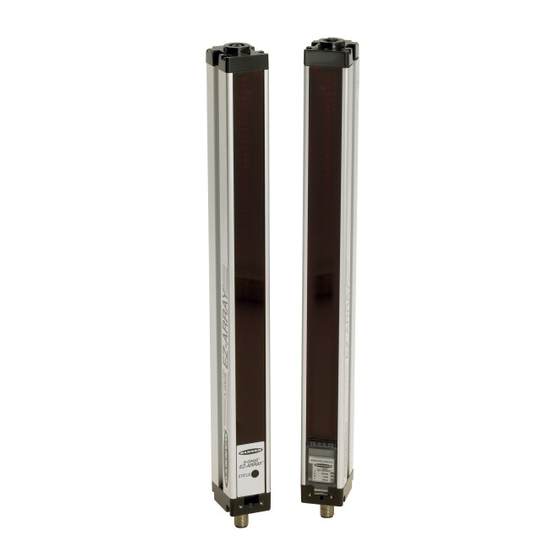
EZ-ARRAY with IO-Link v1.1 2.1 System Components A typical A-GAGE EZ-ARRAY has four components: an emitter Figure 3. Components and a receiver, each with an integral quick-disconnect (QD) fitting, plus an 8-pin QD cordset for the emitter and for the receiver. -
Page 6: Zone Indicators (Beams Blocked Segment)
® ™ A-GAGE EZ-ARRAY with IO-Link v1.1 Table 1: Emitter status indicators Color Description Red ON Status OK Status LED Red Flashing at 1 Hz Error The receiver has a bright Status LED that indicates overall sensing status (OK, marginal alignment, and hardware error). Two other LEDs indicate whether communication is active or if there is an error. - Page 7 ® ™ A-GAGE EZ-ARRAY with IO-Link v1.1 Figure 4. Electronic configuration indicator ‘A’ in this Period ON indicates Period ON position indicates Electronic Configuration indicates Alignment mode Enabled Blanking Configured www.bannerengineering.com - Tel: + 1 888 373 6767...
-
Page 8: Configuration Via Dip Switch Or Io-Link V1.1 Interface
® ™ A-GAGE EZ-ARRAY with IO-Link v1.1 3 Configuration via DIP Switch or IO-Link v1.1 Interface Commonly used configuration options can be set up easily via a six-position DIP switch located behind a hinged clear access panel on the front of the receiver. Access to the DIP switch can be prevented by using the screw-on security plate to hold the clear access panel closed or by disabling them via the IO-Link v1.1 interface. -
Page 9: Gain Configuration
® ™ A-GAGE EZ-ARRAY with IO-Link v1.1 Table 4: Gain, receiver interface, and display configuration with the remote wire Remote Wire Procedure 0.05 ≤ sec. T ≤ 0.8 Process Result sec. From Run Mode: L appears on 3-digit display, along with number 1 or 2, to Access Gain Mode designate gain level Toggle Between Gain... -
Page 10: Blanking
® ™ A-GAGE EZ-ARRAY with IO-Link v1.1 3.3 Blanking If a machine fixture or other equipment blocks one or more sensing beams, the affected beam channels may be blanked. The blanking option causes the receiver to ignore the status of blanked beams for measurement mode calculations. For example, if a machine fixture blocks one or more beams during sensing, the output data will be incorrect;... - Page 11 ® ™ A-GAGE EZ-ARRAY with IO-Link v1.1 Contiguous Last Beam Blocked (CLBB) The location of the last blocked beam in the largest group of adjacent blocked beams. Carpet Nap and Carpet Edge These measurement modes are used to measure the location of carpet backing and tuft and are selectable only via the IO-Link v1.1 interface and only when the Scan Type Carpet Nap is selected.
- Page 12 ® ™ A-GAGE EZ-ARRAY with IO-Link v1.1 Figure 6. Measurement mode - LBB-FBB Receiver Last Beam Blocked (LBB) First Beam Blocked (FBB) Emitter In Last Beam Blocked mode, the last beam is #55 of 60. In First Beam Blocked mode, the first beam is #20 of 60. Figure 7.
-
Page 13: Outputs
® ™ A-GAGE EZ-ARRAY with IO-Link v1.1 3.5 Outputs All models have two analog outputs and two discrete outputs (discrete output 1 is an IO-Link output). The analog outputs are 0–10 V. They may be configured (via DIP switch or IO-Link interface) for either a positive or negative slope. -
Page 14: Straight Scan
® ™ A-GAGE EZ-ARRAY with IO-Link v1.1 Scanning Straight Scan Single-Edge Double-Edge Scan (per Edge) Method Scan Low- High-Excess- Step Size (Number of Beams) Contrast Gain 5 mm 2.5 mm 2.5 mm 2.5 mm 2.5 mm 2.5 mm 2.5 mm Edge Resolution 5 mm (0.2") 2.5 mm (0.1") -
Page 15: Maximum Scan Times In Sio Mode
® ™ A-GAGE EZ-ARRAY with IO-Link v1.1 Figure 8. Double-edge scan Step #1 Step #2 Step #3 Beam #1 of 30 Beam #15 Beam #23 clear blocked blocked Emitter Receiver Step #4 Step #5 Step #6 Beam #17 Beam #19 clear Beam #18 blocked blocked... -
Page 16: Installation Instructions
® ™ A-GAGE EZ-ARRAY with IO-Link v1.1 4 Installation Instructions 4.1 Mounting the Emitter and Receiver Compact EZ-ARRAY emitters and receivers are easy to handle during mounting. When mounted to the sensor end caps, the supplied mounting brackets allow ±30° rotation. An emitter may be separated from 400 mm to 4 m (16 in to 13 ft) from its receiver. - Page 17 ® ™ A-GAGE EZ-ARRAY with IO-Link v1.1 Figure 12. Mechanical alignment When alignment is difficult, use alignment tool LAT-1-SS to assist or confirm alignment by providing a visible red dot along the sensor's optical axis. Snap the LAT-1 clip onto the sensor housing, turn on its laser emitter, and use a strip of retroreflective tape at the opposite sensor to see the dot.
-
Page 18: Wiring Diagrams
® ™ A-GAGE EZ-ARRAY with IO-Link v1.1 Figure 14. Angled or horizontal installations Emitter Receiver level level Level Surface For vertical installations, verify that: • Distance X at emitter and receiver are equal. • Both sensors are level/plumb (check both the side and face). •... -
Page 19: Optical Alignment
® ™ A-GAGE EZ-ARRAY with IO-Link v1.1 Figure 16. PNP Outputs without IO-Link Master 18-30V dc Power – Receiver Emitter Power Supply V+ Power Supply V+ Power Supply V- Power Supply V- Sync Sync V Out 1 V Out 2 Out 1 Load Out 2... - Page 20 ® ™ A-GAGE EZ-ARRAY with IO-Link v1.1 a. Verify that the emitter and receiver are pointed squarely at each other. A straightedge or level can help determine the direction the sensor is facing. b. Slightly loosen the sensor mounting screws and rotate one sensor to the left and right, noting the positions where the receiver Zone indicators turn from green to red;...
-
Page 21: Receiver User Interface
® ™ A-GAGE EZ-ARRAY with IO-Link v1.1 5 Receiver User Interface The receiver user interface comprises the six-position DIP switch, two push buttons, 3-digit display, and other indicators present on the receiver (see Status Indicators for more complete status indicator information). The receiver interface enables configuration of standardized combinations of the EZ-ARRAY sensing options (output configuration, scanning methods and modes);... -
Page 22: Scanning Modes (S1 And S2)
® ™ A-GAGE EZ-ARRAY with IO-Link v1.1 5.1.1 Scanning Modes (S1 and S2) Maximum Scan Times in SIO Mode on p. 15 for scan times. Double-Edge Step 1 (S1 ON, S2 OFF) Double-Edge Step 1 can be used when three or fewer opaque objects are presented to the light curtain at one time. The advantage of this mode is improved sensor edge resolution (2.5 mm). -
Page 23: Electronic Alignment And Blanking - Receiver Interface
® ™ A-GAGE EZ-ARRAY with IO-Link v1.1 5.2.1 Electronic Alignment and Blanking - Receiver Interface To initiate the electronic alignment procedure, use a small screwdriver to press the Alignment/Blanking button for two or more seconds. The left-hand digit of the 3-digit display will read "A" (representing alignment); the right two digits will show the number of beams blocked. -
Page 24: Additional Information
® ™ A-GAGE EZ-ARRAY with IO-Link v1.1 6 Additional Information 6.1 IO-Link Overview For the latest IO-Link protocol and specifications, please visit the web site at http://www.io-link.com IO-Link is a point-to-point communication link between master and slave. It can be used to automatically parameterize sensors and transmit process data. -
Page 25: Io-Link Master
For detailed information on the IODD file interface and parameters, see IO-Link Data Reference Guide EZ-ARRAY v1.1 (p/n 220588). For the latest IODD packages, please refer to the Banner website at http://www.bannerengineering.com/IO-Link. www.bannerengineering.com - Tel: + 1 888 373 6767... -
Page 26: Troubleshooting
Remove and re-apply sensor supply voltage. If the error code 2 is removed, electrically re-align the sensor Receiver Alignment/Blanking Alignment/Blanking Button (Electronic Alignment) on p. 22). If the error code persists, contact Banner for Configuration Error further problem-solving techniques. Reserved for Factory Replace the receiver. -
Page 27: Specifications
® ™ A-GAGE EZ-ARRAY with IO-Link v1.1 8 Specifications Emitter/Receiver Range IO-Link Interface Standard models: 400 mm to 4 m (16 in to 13 ft) Baud Rate: 38,400 bps for COM2 Process Data Width: 240 bits Supply Power Requirements Minimum Object Detection Size Emitter/Receiver Pair (Exclusive of Discrete Load): Less than 9 W Power-up delay: 2 seconds Straight Scan, Low-Contrast: 5 mm (0.2 in) -
Page 28: Emitter And Receiver Dimensions
® ™ A-GAGE EZ-ARRAY with IO-Link v1.1 Connections Environmental Rating IO-Link Interface: The receiver uses a cable splitter that converts the 8- IEC IP65 pin connector to a compatible M12 IO-Link connector Operating Conditions Other sensor connections: 8-conductor quick-disconnect cables (one –40 °C to +70 °C (–40 °F to +158 °F) each for emitter and receiver), ordered separately;... -
Page 29: Standard Bracket Dimensions
® ™ A-GAGE EZ-ARRAY with IO-Link v1.1 Emitter or Receiver Model Housing Length L1 Distance Between Bracket Holes L2 L3 Defined Area Y EA5..1500.. 1578 mm (62.1 in) 1611 mm (63.4 in) 1550 mm (61.0 in) 1500 mm (59.1 in) EA5..1800.. -
Page 30: Accessories
® ™ A-GAGE EZ-ARRAY with IO-Link v1.1 9 Accessories 9.1 Cordsets and Connections 8-Pin Threaded M12 Cordsets with Shield—Single Ended Model Length Style Dimensions Pinout (Female) MAQDC-806 2 m (6.56 ft) MAQDC-815 5 m (16.4 ft) 44 Typ. 10 m (32.81 MAQDC-830 Straight M12 x 1... -
Page 31: Alignment Aids
® ™ A-GAGE EZ-ARRAY with IO-Link v1.1 IO-Link Cable Splitters Model Length Description CSB-M1250M1280 8-pin female to split 5-pin male and 8-pin female, M12, straight, with shield (IO-Link pin 2 is Voltage Output 1) CSB-M1240M1280* 8-pin female to split 4-pin male and 8-pin female, M12, straight, with shield (IO-Link pin 2 is Discrete Output 2) * Shipped with all EZ-ARRAY IO-Link receivers... -
Page 32: Accessory Mounting Brackets And Stands
® • Retrofit for Banner MINI-SCREEN • Order EZA-MBK-20U for bracket with M5 and M6 mounting hardware Hole size:A = ø7 × 25 (2); B = ø7 × 18; C = ø21.5;... -
Page 33: Product Support And Maintenance
10.3 Banner Engineering Corp. Limited Warranty Banner Engineering Corp. warrants its products to be free from defects in material and workmanship for one year following the date of shipment. Banner Engineering Corp. will repair or replace, free of charge, any product of its manufacture which, at the time it is returned to the factory, is found to have been defective during the warranty period. This warranty does not cover damage or liability for misuse, abuse, or the improper application or installation of the Banner product.
Need help?
Do you have a question about the A-GAGE EZ-ARRAY and is the answer not in the manual?
Questions and answers