Banner A-GAGE EZ-ARRAY Instruction Manual
Io-link
Hide thumbs
Also See for A-GAGE EZ-ARRAY:
- Instruction manual (33 pages) ,
- Instruction manual (48 pages)

Subscribe to Our Youtube Channel
Related Manuals for Banner A-GAGE EZ-ARRAY


Summary of Contents for Banner A-GAGE EZ-ARRAY
- Page 1 ® ™ A-GAGE EZ-ARRAY IO-Link Instruction Manual Instruction Manual Original Instructions 157954 Rev. C 16 May 2017 © Banner Engineering Corp. All rights reserved 157954...
-
Page 2: Table Of Contents
® ™ A-GAGE EZ-ARRAY IO-Link Instruction Manual Contents 1 Features ..................................4 2 Overview ..................................5 2.1 System Components ....................................6 2.2 Features ......................................... 6 2.3 Configuration via DIP Switch or IO-Link Interface ..........................6 2.3.1 Outputs ..................................... 7 2.3.2 Display Invert .................................... - Page 3 ..................................37 6.6.4 System Info and Status ................................37 6.6.5 Receiver and Emitter Version Info ............................39 6.6.6 Communications Version Info ..............................39 6.6.7 Alignment/Blanking Routine ..............................39 7 Banner Engineering Corp Limited Warranty ........................41 7.1 Contact Us ......................................41...
-
Page 4: Features
® ™ A-GAGE EZ-ARRAY IO-Link Instruction Manual 1 Features • A cost-effective, two-piece measuring light curtain designed for quick and simple installations with the sophistication to handle the toughest sensing applications • Excels at high-speed, precise process monitoring and inspection, profiling, and web-guiding applications •... -
Page 5: Overview
® ™ A-GAGE EZ-ARRAY IO-Link Instruction Manual 2 Overview ® ™ The A-GAGE EZ-ARRAY measuring light screen is ideal for such applications as on-the-fly product sizing and profiling, edge-guiding and center-guiding, loop tensioning control, hole detection, parts counting, and similar uses. Emitters and receivers are available with arrays from 150 to 2400 mm (5.9 in to 94.5 in) long. -
Page 6: System Components
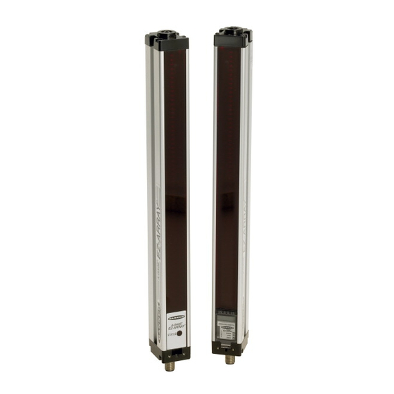
EZ-ARRAY IO-Link Instruction Manual 2.1 System Components A typical A-GAGE EZ-ARRAY has four components: an emitter and a receiver, each with an integral quick-disconnect (QD) fitting, plus an 8- pin QD cordset for the emitter and for the receiver. For applications that use the IO-Link interface, an additional cable splitter is used to convert the receiver 8-pin connector to a compatible M12 connector. -
Page 7: Outputs
® ™ A-GAGE EZ-ARRAY IO-Link Instruction Manual 2.3.1 Outputs All models have two analog outputs and two discrete outputs (discrete output 1 is an IO-Link output). The analog outputs are 0–10V voltage. They may be configured (via DIP switch or IO-Link interface) for either a positive or negative slope. -
Page 8: Blanking Indicator
® ™ A-GAGE EZ-ARRAY IO-Link Instruction Manual During gain adjust mode, the display reads “ ” followed by “1” or “2” to indicate the gain level. (A “1” represents high excess gain, and a “2” represents low contrast.) If a sensing error occurs, the display reads “c” followed by a number that corresponds to the recommended corrective action (see Troubleshooting and Error Codes). -
Page 9: Scanning Method
® ™ A-GAGE EZ-ARRAY IO-Link Instruction Manual • Gate - Falling Edge - The receiver scans once for each high-to-low gate transition. (Multiple transitions cannot be faster than the sensor's response for them to be reliably detected.) Process Remote Wire Procedure 0.05 ≤ sec. T ≤ 0.8 sec. Result Alignment / Access Alignment Mode... -
Page 10: Straight Scan
® ™ A-GAGE EZ-ARRAY IO-Link Instruction Manual Scanning Method Straight Scan Single-Edge Scan Double-Edge Scan (per Edge) Low- High-Excess- Step Size (Number of Beams) Contrast Gain Minimum Object 5 mm (0.2 10mm (0.4 20mm (0.8 30mm (1.2 90mm (3.6 170mm (6.8 10 mm (0.4 in) 10mm (0.4 in) 50mm (2 in) -
Page 11: Maximum Scan Times
® ™ A-GAGE EZ-ARRAY IO-Link Instruction Manual Step #1 Step #2 Step #3 Beam #1 of 30 Beam #15 Beam #23 clear blocked blocked Emitter Receiver Step #4 Step #5 Step #6 Beam #17 Beam #19 clear Beam #18 blocked blocked 2.6.4 Maximum Scan Times Maximum Scan Times (in milliseconds) -
Page 12: Electronic Alignment Routine
® ™ A-GAGE EZ-ARRAY IO-Link Instruction Manual When using the IO-Link interface, low-contrast sensing provides a fine-tune sensitivity setting of 15% to 50%. When using the receiver interface, low-contrast sensitivity is always 30%. EZ-ARRAY MODS 1 Gain Setting Scan Method EZ-ARRAY Resolution Low Contrast Straight Scan... -
Page 13: Analog Output Configuration
® ™ A-GAGE EZ-ARRAY IO-Link Instruction Manual Receiver "Beam Location" Modes First Beam Blocked (FBB) The location of the first blocked beam. Last Beam Made (LBM) First Beam Made (FBM) First Beam Made (FBM) Emitter The location of the first made (unblocked) beam. In Last Beam Made mode, Last Beam Blocked (LBB) last beam is #50 of 60... -
Page 14: Discrete Output Configuration
® ™ A-GAGE EZ-ARRAY IO-Link Instruction Manual 2.12 Discrete Output Configuration Discrete Output 1; Receiver Interface When the receiver interface is used for configuration, the measurement mode assigned to discrete output 1 is the same as that assigned to analog output 1. Discrete Output 2;... -
Page 15: Components And Specifications
® ™ A-GAGE EZ-ARRAY IO-Link Instruction Manual 3 Components and Specifications 3.1 Sensor Models Discrete Output 2 Array Length Y 3 Emitter/Receiver Model IO-Link Analog Output Total Beams EA5E150Q Emitter 150mm (5.9 in) EA5R150XKQ Receiver Voltage (0-10V) EA5E300Q Emitter 300mm (11.8 in) EA5R300XKQ Receiver Voltage (0-10V) EA5E450Q Emitter... - Page 16 ® ™ A-GAGE EZ-ARRAY IO-Link Instruction Manual 8-Pin Threaded M12/Euro-Style Cordsets―Double Ended Model (8-pin/8-pin ) 4 Length Style Dimensions Pinout DEE2R-81D 0.31 m (1 ft) Female DEE2R-83D 0.91 m (3 ft) DEE2R-88D 2.44 m (8 ft) 40 Typ. DEE2R-815D 4.57 m (15 ft) DEE2R-825D 7.62 m (25 ft) Male...
-
Page 17: Alignment Aids
20 mm to 40 mm dual channel and center slot. allows mounting to single channel framing • Retrofit for Banner MINI-SCREEN ® • Order EZA-MBK-20U for bracket with M5 and M6 mounting hardware Hole center spacing: A = 44.4, B = 20, C = 40 Hole size: A = 10.2 ×... -
Page 18: Replacement Parts
® ™ A-GAGE EZ-ARRAY IO-Link Instruction Manual 3.5 Replacement Parts Description Model Access cover with label - receiver EA5-ADR-1 Access cover security plate (includes 2 screws, wrench) EZA-TP-1 Wrench, security EZA-HK-1 Standard bracket kit with hardware (includes 2 end brackets and hardware to Black EZA-MBK-11 mount to MSA Series stands) -
Page 19: Emitter And Receiver Dimensions
® ™ A-GAGE EZ-ARRAY IO-Link Instruction Manual 3.7 Emitter and Receiver Dimensions 36.0 mm (1.42") 45.2 mm 12 mm (1.78") (0.47") 56.0 mm (2.20") 59 mm IO-Link (2.3") 65 mm Splitter 4.2 mm R13 mm (0.5") (2.6") (0.17") minimum bend With Cable Splitter Connection With Cable Connection Emitter or Receiver Model... -
Page 20: Standard Bracket Dimensions
® ™ A-GAGE EZ-ARRAY IO-Link Instruction Manual 3.8 Standard Bracket Dimensions End Cap Brackets (model EZA-MBK-11*) Center Bracket (model EZA-MBK-12**) 4 x 5.8 mm (0.23") wide slots 4 x R 19.4 mm Ø 21.5 mm 20 mm (0.76") (0.85") (0.79") 55 mm Ø... -
Page 21: Installation And Alignment
® ™ A-GAGE EZ-ARRAY IO-Link Instruction Manual 4 Installation and Alignment 4.1 Mounting the Emitter and Receiver Compact EZ-ARRAY emitters and receivers are easy to handle during mounting. When mounted to the sensor end caps, the supplied mounting brackets allow ±30° rotation. An emitter may be separated from 400 mm to 4 m (16 in to 13 ft) from its receiver. From a common point of reference, make measurements to locate the emitter and receiver in the same plane, with their midpoints and display ends directly opposite each other. -
Page 22: Wiring Diagrams
® ™ A-GAGE EZ-ARRAY IO-Link Instruction Manual Verify that: • The emitter and receiver are directly opposite each other, and nothing is interrupting the beams. • The sensing area is the same distance from a common reference plane for each sensor. •... -
Page 23: Optical Alignment
® ™ A-GAGE EZ-ARRAY IO-Link Instruction Manual Wiring with an IO-Link Master Receiver Emitter Power Supply V+ Power Supply V+ IO-Link Power Supply V- Cable Power Supply V- Sync Splitter Sync Out 2 can be either Out 2* Discrete Output 2 or Voltage Output 1, IO-Link depending on splitter... - Page 24 ® ™ A-GAGE EZ-ARRAY IO-Link Instruction Manual Receiver Interface Indicators during Alignment All Beams Either Clear or Blanked Some Beams Blocked or Mis-Aligned Out of Alignment Some ON Red (zones with blocked All ON Red (Some beams blocked in Zone Indicators All ON Green beams) Some ON Green (zones with all each zone)
-
Page 25: Receiver User Interface
® ™ A-GAGE EZ-ARRAY IO-Link Instruction Manual 5 Receiver User Interface The receiver user interface comprises the six-position DIP switch, two push buttons, 3-digit display, and other indicators present on the receiver (see Status Indicators for more complete status indicator information). The receiver interface enables configuration of standardized combinations of the EZ-ARRAY sensing options (output configuration, scanning methods and modes);... -
Page 26: Measurement Modes (S3 And S4)
® ™ A-GAGE EZ-ARRAY IO-Link Instruction Manual Single-Edge Scan (S1 OFF, S2 OFF) Single-Edge Scan can be used when a single opaque object is presented to the light curtain at one time. The object must block the "bottom" channel (the channel closest to the receiver display). Like the double-edge scans, the sensor edge resolution is 2.5 mm. -
Page 27: Flashing "000" On The 3-Digit Display
Receiver Alignment/Blanking Configuration Remove and re-apply sensor supply voltage. If the error code 2 is removed, electrically re-align the sensor Error (Alignment/Blanking Button). If the error code persists, contact Banner for further problem-solving techniques. Reserved for Factory Replace the receiver. -
Page 28: Io-Link Interface
® ™ A-GAGE EZ-ARRAY IO-Link Instruction Manual 6 IO-Link Interface 6.1 Overview For the latest IO-Link protocol and specifications, please visit the web site at http://www.io-link.com IO-Link is a point-to-point communication link between master and slave. It can be used to automatically parameterize sensors and transmit process data. -
Page 29: Electrical Interface
Banner_Engineering-EA5RXK-pic.png This IO-Link IODD package is contained on the supplied IO-Link Device Description Resource CD (P/N 18491). For the latest IODD packages, please refer to the Banner website at http://www.bannerengineering.com/IO-Link. 6.5 Configuration Data IO-Link models of the EZ-ARRAY use the Service Parameter Data Unit (SPDU) channel for providing read-write access to configuration data. -
Page 30: Blanking Configuration
® ™ A-GAGE EZ-ARRAY IO-Link Instruction Manual SPDU Byte Position Member Name Index Sub-Index Scan Type Remote Teach/Gate Scan Type Value Type Description Straight Straight Scanning Single Edge Scanning for Single Edge Double Edge - Step 1 Scanning for Edges of up to 3 objects (fires every channel) Double Edge - Step 2 Scanning for Edges of up to 3 objects (fires channels 1, 3, 5, ...) Double Edge - Step 4... -
Page 31: General Configuration
® ™ A-GAGE EZ-ARRAY IO-Link Instruction Manual Blanking Bit-Mask Value Status Description Blanked The channel will be skipped during scanning 6.5.3 General Configuration The General Configuration contains the general settings for the EZ-ARRAY. SPDU Byte Position Member Name Index Sub-Index Emitter Power Gain Method Low Contrast Sensitivity... - Page 32 ® ™ A-GAGE EZ-ARRAY IO-Link Instruction Manual Low Contrast Sensitivity Value Function Description Blocked threshold is set 25% below aligned signal Blocked threshold is set 30% below aligned signal Blocked threshold is set 35% below aligned signal Blocked threshold is set 40% below aligned signal Blocked threshold is set 45% below aligned signal Blocked threshold is set 50% below aligned signal HW Interface Flags...
-
Page 33: Analog Output 1 Configuration
® ™ A-GAGE EZ-ARRAY IO-Link Instruction Manual Number of Dirty Channels Range Description 1-360 Number of channels that need to be dirty before indicator is lit (150 to 1800 mm Length Models) 1-480 Number of channels that need to be dirty before indicator is lit (2100 to 2400 mm Length Models) Time of Service Range Description... -
Page 34: Analog Output 2 Configuration
® ™ A-GAGE EZ-ARRAY IO-Link Instruction Manual SPAN Output (Analog Output 1 & 2) Range Description 0-4095 Maximum DAC value of Analog Output (MUST be > NULL Output) 6.5.5 Analog Output 2 Configuration The Analog Output 2 Configuration contains the settings for the second analog output. SPDU Byte Position Member Name... -
Page 35: Discrete Output 2 Configuration
® ™ A-GAGE EZ-ARRAY IO-Link Instruction Manual Hysteresis LOW (Discrete Output 1 & 2) Range Description 0-479 Lower hysteresis threshold for discrete output (MUST be < Threshold LOW) (2100 to 2400 mm Length Models) Hysteresis HIGH (Discrete Output 1 & 2) Range Description 2-361... -
Page 36: All Measurements
® ™ A-GAGE EZ-ARRAY IO-Link Instruction Manual Measurement 1 and Measurement 2 Range Description 0-1920 Measurements are represented in 4x channel resolution 6.6.2 ALL Measurements The ALL Measurements section contains the current values of all the available measurements. SPDU Byte Position Member Name Index Sub-Index... -
Page 37: Channel States
® ™ A-GAGE EZ-ARRAY IO-Link Instruction Manual SPDU Sub-Index Bit Position Flag Description Value Slope 0 = Negative, 1 = Positive Measurement 0 = Measurement 2, 1 = Measurement 1 ZERO Value 00 = Hold, 01 = Minimum, 10 = Maximum Peak Detect 0 = Disabled, 1 = Enabled Peak Detect Direction... - Page 38 ® ™ A-GAGE EZ-ARRAY IO-Link Instruction Manual Number of Emitter Channels Range Description 30-480 Number of channels the emitter has (multiples of 30) Emitter First Bad Channel Range Description 0-480 First channel that emitter is unable to fire (0 = no bad channels) Number of Receiver Channels Range Description...
-
Page 39: Receiver And Emitter Version Info
® ™ A-GAGE EZ-ARRAY IO-Link Instruction Manual Discrete Outputs SPDU Sub-Index Bit Position Function Description Discrete Output 1 0 = OFF, 1 = ON Discrete Output 2 0 = OFF, 1 = ON Analog Output 1 DAC and Analog Output 2 DAC Range Description 0-4095... - Page 40 ® ™ A-GAGE EZ-ARRAY IO-Link Instruction Manual 1: Access 4: Access Alignment Mode Blanking Mode 2: Status: 5: Status: Alignment Blanking 0: Idle Mode Mode 6: Exit 3: Exit Blanking Mode Alignment Mode Overview: Electronic Alignment Routine Overview: Blanking for details on Alignment and Blanking routines. The Alignment Status can be read in the System Info and Status section to check if the Alignment routine was successful.
-
Page 41: Banner Engineering Corp Limited Warranty
7 Banner Engineering Corp Limited Warranty Banner Engineering Corp. warrants its products to be free from defects in material and workmanship for one year following the date of shipment. Banner Engineering Corp. will repair or replace, free of charge, any product of its manufacture which, at the time it is returned to the factory, is found to have been defective during the warranty period. - Page 42 ® ™ A-GAGE EZ-ARRAY IO-Link Instruction Manual China Address: Phone: +86 212 422 6888 Banner Engineering Shanghai Rep Office Website: www.bannerengineering.com.cn Xinlian Scientific Research Building Level 12, Building 2 Email: sensors@bannerengineering.com.cn 1535 Hongmei Road, Shanghai 200233, China Japan Address: Phone: +81 (0)6 6309 0411...
Need help?
Do you have a question about the A-GAGE EZ-ARRAY and is the answer not in the manual?
Questions and answers