Table of Contents
Advertisement
Quick Links
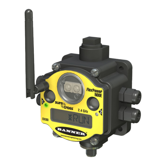
SureCross DX80 FlexPower Thermocouple Node
Configurable temperature Node with thermocouple inputs and discrete I/O
Features
IP20 Base
900 MHz
For additional information, the most recent version of all documentation, and a complete list of accessories, refer to Banner Engineering's
website, www.bannerengineering.com/surecross.
Models
Model
Frequency
DX80N9X2S2N2T
900 MHz ISM Band
DX80N2X2S2N2T
2.4 GHz ISM Band
DX80N9X2S2N2TC
900 MHz ISM Band IP20, NEMA 1
DX80N2X2S2N2TC
2.4 GHz ISM Band
Internal antenna models are also available. For more information, contact your local Banner Engineering Corp. representative.
WARNING: Not To Be Used for Personnel Protection
Never use this product as a sensing device for personnel protection. Doing so could lead to serious injury
or death. This product does NOT include the self-checking redundant circuitry necessary to allow its use in
personnel safety applications. A sensor failure or malfunction can cause either an energized or de-ener-
gized sensor output condition.
P/N 131297 rev. I
The SureCross™ wireless system is a radio frequency network with integrated I/O that
can operate in most environments while eliminating the need for wiring runs. Systems
are built around a Gateway, which acts as the wireless network master device, and one
or more Nodes.
• Wireless industrial I/O device with up to three configurable thermocouple inputs (de-
faults to J-type), two selectable discrete inputs, and two NMOS discrete outputs
• One thermistor input used for integrated cold junction compensation (CJC)
• FlexPower™ power options allows for +10 to 30V dc, solar, and battery power sour-
ces for low power applications.
IP67 Base
2.4 GHz
• DIP switches for user configuration
• Frequency Hopping Spread Spectrum (FHSS) technology and Time Division Multi-
ple Access (TDMA) control architecture combine to ensure reliable data delivery
within the unlicensed Industrial, Scientific, and Medical (ISM) band
• Transceivers provide bidirectional communication between the Gateway and Node,
including fully acknowledged data transmission
• Lost RF links are detected and relevant outputs set to user-defined conditions
• The DX80...C models are certified for use in Class I, Division 2, Group A, B, C, D;
Zone 2 (Group IIC) Hazardous Locations when properly installed in accordance with
the National Electrical Code, the Canadian Electrical Code, LCIE/ATEX, or applica-
ble local codes/regulations (see Specifications)
Environmental Rating
IP67, NEMA 6
Class I, Division 2, Group A, B, C, D Haz-
ardous Locations (see Specifications)
8/18/2011
I/O
Inputs: Three thermocouople, two select-
able discrete, one thermistor input for
CJC
Outputs: Two NMOS sinking discrete
0 131297
3
Advertisement
Table of Contents

Related Manuals for Banner SureCross FlexPower DX80 Series


Summary of Contents for Banner SureCross FlexPower DX80 Series
- Page 1 Zone 2 (Group IIC) Hazardous Locations when properly installed in accordance with the National Electrical Code, the Canadian Electrical Code, LCIE/ATEX, or applica- ble local codes/regulations (see Specifications) For additional information, the most recent version of all documentation, and a complete list of accessories, refer to Banner Engineering's website, www.bannerengineering.com/surecross. Models...
- Page 2 The UCT requires a special USB to RS-485 (model number BWA- HW-006) converter cable to pass information between your computer and the Gateway. Download the most recent revisions of the UCT software from Banner Engineering's website: http://www.banneren- gineering.com/wireless. www.bannerengineering.com - tel: 763-544-3164...
-
Page 3: Wiring Diagrams
SureCross DX80 FlexPower Thermocouple Node Wiring Diagrams 5-pin Euro-Style Hookup (Nodes) Wiring the 5-pin Euro-style connector depends on the model and power requirements of the device. Wire No. Wire Color 10 to 30V dc Powered Nodes Battery Powered Nodes Brown 10 to 30V dc White Blue... - Page 4 SureCross DX80 FlexPower Thermocouple Node Terminal Block (IP20) For the DX8x...C models, PWR in the wiring diagram refers to V+ on the wiring board and GND in the wiring diagram refers to V- on the wiring board. DIx. Discrete IN x. DOx.
-
Page 5: Additional Information
For additional information, including installation and setup, weatherproofing, device menu maps, troubleshooting, and a list of accesso- ries, refer to one of the following product manuals • SureCross Quick Start Guide: Banner part number 128185 • SureCross Wireless I/O Network Manual: 132607 •... -
Page 6: Device Configuration
SureCross DX80 FlexPower Thermocouple Node Modbus Register Table (High Resolution Mode) Modbus Holding Register I/O Type Units I/O Range Holding Register Terminal Value Block La- bels Gateway Any Node Min. Max. Val- Min. Max. Value (Dec.) (Dec.) 1 + (Node# × 16) Discrete IN 1 2 + (Node# ×... -
Page 7: Dip Switch Settings
SureCross DX80 FlexPower Thermocouple Node 3. Gently unplug the ribbon cable from the board mounted into the bottom housing. For Class I, Division 2 certified devices, skip this step (the ribbon cable is glued). 4. Remove the black cover plate from the bottom of the device's cover. The DIP switches are located behind the rotary dials. -
Page 8: Verify Communications
SureCross DX80 FlexPower Thermocouple Node ** In high resolution mode, the temperature = (Modbus register value) ÷ 20. In low resolution mode, the temperature = (Modbus register value) ÷ 2. Address Mode The SureCross wireless devices may use one of two types of addressing modes: rotary dial addressing or extended addressing. In rotary dial address mode, the left rotary dial establishes the network ID and the right rotary dial sets the device ID. -
Page 9: Specifications
SureCross DX80 FlexPower Thermocouple Node LED 1 LED 2 Gateway Status Node Status Modbus Communication Active (yellow flashing) Modbus Communication Error No radio link (when flashing (red flashing) once every three seconds) For Gateway and Ethernet Bridge systems, active Modbus communication refers to the communication between the Gateway and the Ethernet Bridge. - Page 10 Radiated Immunity: 10 V/m, 80-2700 MHz (EN61000-6-2) Refer to the SureCross™ DX80 Wireless I/O Network product manual, Banner p/n 132607, for installation and waterproofing instructions. Operating the devices at the maximum operating conditions for extended periods can shorten the life of the device.
-
Page 11: Antenna Installation
Banner Engineering Corp. warrants its products to be free from defects in material and workmanship for one year following the date of shipment. Banner Engineering Corp. will repair or replace, free of charge, any product of its manufacture which, at the time it is returned to the factory, is found to have been defective during the warranty period. - Page 12 WHETHER ARISING UNDER COURSE OF PERFORMANCE, COURSE OF DEALING OR TRADE USAGE. This Warranty is exclusive and limited to repair or, at the discretion of Banner Engineering Corp., replacement. IN NO EVENT SHALL BANNER ENGINEERING CORP. BE LIABLE TO BUYER OR ANY OTHER PERSON OR ENTITY FOR ANY EXTRA COSTS, EXPEN-...
Need help?
Do you have a question about the SureCross FlexPower DX80 Series and is the answer not in the manual?
Questions and answers