Table of Contents
Advertisement
Quick Links
Advertisement
Table of Contents
Troubleshooting

Related Manuals for Keysight Technologies E4981A


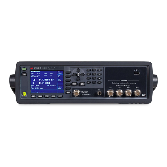
Summary of Contents for Keysight Technologies E4981A
- Page 1 Keysight E4981A 120 Hz/1 kHz/1 MHz Capacitance Meter Service Guide...
- Page 3 E4981A Keysight 120Hz/1kHz/1MHz Capacitance Meter Service Guide First Edition FIRMWARE REVISIONS This manual applies directly to instruments that have the firmware revision A.01.00 or higher. For additional information about firmware revisions, see Appendix A. Keysight Part No. E4981-90100 March 2009...
- Page 4 The information contained in this document is subject to change without notice. This document contains proprietary information that is protected by copyright. All rights are reserved. No part of this document may be photocopied, reproduced, or translated to another language without the prior written consent of Keysight Technologies. ® ®...
- Page 5 The E4981A complies with INSTALLATION CATEGORY II as well as POLLUTION DEGREE 2 in IEC61010-1. The E4981A is an INDOOR USE product. NOTE The LEDs in the E4981A are Class 1 in accordance with IEC60825-1, CLASS 1 LED PRODUCT NOTE This equipment is MEASUREMENT CATEGORY I (CAT I).
- Page 6 safety features are maintained in operational condition. • Dangerous Procedure Warnings Warnings, such as the example below, precede potentially dangerous procedures throughout this manual. Instructions contained in the warnings must be followed. WARNING Dangerous voltage levels, capable of causing death, are present in this instrument. Use extreme caution when handling, testing, and adjusting this instrument.
- Page 7 Certification Keysight Technologies certifies that this product met its published specifications at the time of shipment from the factory. Keysight Technologies further certifies that its calibration measurements are traceable to the United States National Institute of Standards and Technology, to the extent allowed by the Institution’s calibration facility, or to the calibration facilities of other International Standards Organization members.
- Page 8 Typeface Conventions Sample (bold) Boldface type is used for emphasis. Sample (Italic) Italic type is used for emphasis and manual title. [Sample] key Indicates a hardkey (key on the front panel or external keyboard) labeled “Sample.” “key” may be omitted. menu/button/box Indicates a menu/button/box on the screen labeled Sample...
-
Page 9: Table Of Contents
Contents 1. General Information Organization of Service Guide ............14 Instruments Covered by This Manual. - Page 10 Contents To Check the Handler Interface Function ..........60 To Check the Scanner Interface Function .
- Page 11 Contents Tools Required ..............101 Removal Procedure .
- Page 12 How to update E4981A firmware using USB/GPIB interface ....... .
- Page 13 Contents L ................145 M .
- Page 14 Contents...
-
Page 15: General Information
General Information This Service Guide is a guide to servicing the E4981A 20 Hz/1 kHz/1 MHz Capacitance Meter. The Service Guide provides information about performance test, adjustment, troubleshooting, and repairing the E4981A. -
Page 16: Organization Of Service Guide
This chapter provides the adjustment information for the E4981A to ensure that it is within its specifications. The adjustment must be performed Keysight’s qualified service personnel. If you need the adjustment for your E4981A, it should be sent to the nearest Keysight Technologies service office. -
Page 17: Instruments Covered By This Manual
Changes supplement. The supplement for this manual is identified by this manual’s printing data and is available from Keysight Technologies. If the serial prefix or number of an instrument is lower than that on the title page of this manual, see Appendix A, Manual Changes. -
Page 18: Required Equipment
General Information Required Equipment Required Equipment Table 1-1 lists the recommended equipment for performance test, adjustment and troubleshooting for E4981A. Table 1-1 Recommended Test Equipment Equipment Critical Specifications Recommended Model Qty. Frequency Counter Frequency Range: 1 MHz Keysight 53131A or Time Base Error <... -
Page 19: Performance Test
Performance Test This chapter provides the outline of the E4981A performance tests. -
Page 20: Introduction
Performance Test Introduction Introduction This chapter provides the performance tests outline for Keysight E4981A. The performance test names are listed in Table 2-1. The test descriptions are described sequentially in the following pages. NOTE Allow the analyzer to warm up for at least 30 minutes before you execute any of the performance tests. -
Page 21: Individual Test Description
Performance Test Individual Test Description Individual Test Description 1. Test Signal Frequency Accuracy Test Description This test checks the frequency accuracy of the E4981A test signal. Specification @23 ± 5 ⋅C Frequency [Hz] Spec. ± 0.02% 120 to 1M *1.Option 001 only. -
Page 22: Test Signal Level Accuracy Test
Performance Test Individual Test Description 2. Test Signal Level Accuracy Test Description This test checks the signal level accuracy of the E4981A source port output signal. Specification @23 ± 5 ⋅C Signal Level [V] Spec. ± 5.0 % 0.1 to 1.0... - Page 23 Performance Test Individual Test Description Test point and limits Cable Length : 2 m Frequency Frequency Level Range Test Limit Measurement Shift Uncertainty ± 5.0 mV ± 0.28 mV 120 Hz 0.1 V 10 uF 18.26 ± 10.0 mV ± 0.15 mV 0.2 V 66.96 ±...
- Page 24 Performance Test Individual Test Description Frequency Frequency Level Range Test Limit Measurement Shift Uncertainty ± 5.0 mV ± 0.12 mV 1 kHz 0.1 V 1 uF 42.84 ± 10.0 mV ± 0.41 mV 0.2 V 24.36 ± 15.0 mV ± 0.21 mV 72.84 0.3 V ±...
- Page 25 Performance Test Individual Test Description Frequency Frequency Level Range Test Limit Measurement Shift Uncertainty ± 5.0 mV ± 1.16 mV -2 % 0.1 V 100 pF 4.31 1 MHz ± 10.0 mV ± 2.32 mV 0.2 V 4.31 ± 15.0 mV ±...
- Page 26 Performance Test Individual Test Description Frequency Frequency Level Range Test Limit Measurement Shift Uncertainty ± 5.0 mV ± 1.17 mV 0.1 V 100 pF 4.30 1 MHz ± 10.0 mV ± 2.33 mV 0.2 V 4.30 ± 15.0 mV ± 3.48 mV 4.31 0.3 V ±...
- Page 27 Performance Test Individual Test Description Frequency Frequency Level Range Test Limit Measurement Shift Uncertainty ± 5.0 mV ± 1.16 mV 0.1 V 100 pF 4.31 1 MHz ± 10.0 mV ± 2.32 mV 0.2 V 4.31 ± 15.0 mV ± 3.48 mV 4.31 0.3 V ±...
-
Page 28: Impedance Measurement Accuracy Test
Performance Test Individual Test Description 3. Impedance Measurement Accuracy Test Description This test checks the impedance measurement accuracy of the E4981A. Specification @23 ± 5 ⋅C < ± (Relative Accuracy + Cal Accuracy) Impedance Accuracy *1.Refer to the Specification Chapter in the User’s Guide for details. - Page 29 Performance Test Individual Test Description Test point and limits Cable Length : 2 m, MEAS TIME : 1 Range : 100 nF Standard Signal Freq Freq Param Test Limit Measurement Level Shift Uncertainty ± 85 pF ± 5.44 pF 100 nF 1 kHz 15.63 ±...
- Page 30 Performance Test Individual Test Description Cable Length : 2 m, MEAS TIME : 1 Range : 100 pF Standard Signal Freq Freq Param Test Limit Measurement Level Shift Uncertainty ± 85 fF ± 11.75 fF 100 pF 7.23 1 MHz ±...
- Page 31 Performance Test Individual Test Description Cable Length : 2 m, MEAS TIME : 8 Range : 220 pF Standard Signal Freq Freq Param Test Limit Measurement Level Shift Uncertainty ± 88 fF ± 13.16 fF 100 pF -2 % 6.68 1 MHz ±...
- Page 32 Performance Test Individual Test Description Cable Length : 2 m, MEAS TIME : 8 Range : 10 nF Standard Signal Freq Freq Param Test Limit Measurement Level Shift Uncertainty ± 7 pF ± 0.61 pF 10 nF 120 Hz 11.60 ±...
- Page 33 Performance Test Individual Test Description Cable Length : 2 m, MEAS TIME : 8 Range : 1 nF Standard Signal Freq Freq Param Test Limit Measurement Level Shift Uncertainty ± 0.7 pF ± 88.49 fF 1 nF 1 kHz 7.91 ±...
- Page 34 Performance Test Individual Test Description Cable Length : 2 m, MEAS TIME : 1 Range : 1 uF Standard Signal Freq Freq Param Test Limit Measurement Level Shift Uncertainty ± 0.85 nF ± 70.05 pF 1 uF 120 Hz 12.13 ±...
- Page 35 Performance Test Individual Test Description Cable Length : 2 m, MEAS TIME : 8 Range : 4.7 uF Standard Signal Freq Freq Param Test Limit Measurement Level Shift Uncertainty ± 1.26 nF ± 81.21 pF 1 uF 120 Hz 15.45 ±...
- Page 36 Performance Test Individual Test Description Cable Length : 0 m, MEAS TIME : 8 Range : 100 pF Standard Signal Freq Freq Param Test Limit Measurement Level Shift Uncertainty ± 70 fF ± 10.04 fF 100 pF -2 % 6.97 1 MHz ±...
-
Page 37: Adjustment
This chapter provides the adjustment information for the E4981A to ensure that it is within its specifications. The adjustment must be performed Keysight’s qualified service personnel. If you need the adjustment for your E4981A, it should be sent to the nearest Keysight Technologies service office. -
Page 38: Safety Considerations
Intentional interruption of the protective ground system for any reason is prohibited. Warm-up for Adjustment Warm-up the E4981A for at least 30 minute before performing any of the following Adjustment procedures to ensure proper results and correct instrument operation. Required Equipment... -
Page 39: Required Adjustment After Replacing Assembly
E4981A, it should be sent to the nearest Keysight Technologies service office. Writing ID This item writes the serial number, option information into the A31 board of the E4981A. Required equipment for the writing ID None Test Signal Level Monitor Adjustment This adjustment calibrate the Signal Level Monitor’s absolute measurement accuracy. -
Page 40: Vrd Gain Adjustment
Adjustment Required Adjustment after Replacing Assembly VRD Gain Adjustment The adjustment calibrate the amplifiers’ gain and phase shift. Required equipment for the VRD Gain adjustment Description Recommended Model 4TP Open Termination Keysight 42090A 1 kΩ Standard Resistor Keysight 42037A Chapter 3... -
Page 41: Trd Rr Adjustment
Adjustment Required Adjustment after Replacing Assembly TRD Rr Adjustment The adjustment calibrate the resistance ratio between neighbor range resistor. Required equipment for the TRD Rr adjustment Description Recommended Model 4TP Open Termination Keysight 42090A Standard Resistor Set Keysight 42030A Impedance Adjustment The adjustment calibrate the capacitance measurement accuracy to measure the standard capacitor as a reference. - Page 42 Adjustment Required Adjustment after Replacing Assembly Description Recommended Model BNC(f)-BNC(f) Adapter Keysight 1250-1830, 4ea Chapter 3...
-
Page 43: Troubleshooting
Troubleshooting This chapter provides the procedure to isolate a faulty assembly in the E4981A. -
Page 44: Introduction
Troubleshooting Introduction Introduction WARNING These servicing instructions are for use by qualified personnel only. To avoid possible electrical shock, do not perform any servicing unless you are qualified to do so. WARNING The opening of covers or removal of parts is likely to expose dangerous voltages. Disconnect the instrument from its power supply beforehand. -
Page 45: To Troubleshoot The Instrument
Step 1. Turn the E4981A power on With the E4981A plugged in and the power turned off, the front panel orange standby LED should be on. When the front panel power switch is turned on, the orange LED should go out and the yellow-green LED should come on. - Page 46 Troubleshooting To Troubleshoot the Instrument Figure 4-1 Primary trouble isolation flowchart Display and Boot-up Problems Problems on Front Panel, LCD Display, Front USB Port, GPIB Interface, USB Interface, LAN Port, External Trigger Input, Handler Interface or Scanner Interface. Power on Go to Power on Sequence Power up normally? Power on...
-
Page 47: Power On Sequence Troubleshooting
Requirements in Appendix B. Check the Power Supply Unit Output Step 1. Remove the E4981A’s outer cover. Step 2. Turn the E4981A power on. Step 3. Check the output voltage (+3.3 V and +5 V) of the power supply unit. LED on A31 board are turn on with green if the power unit is worked correctly. -
Page 48: Check Booting Process
1. With the E4981A plugged in and the power turned off, the orange standby LED should be on. If the orange LED doesn’t light, check the key flex circuit, display interface board, A31 board, and relevant cables. -
Page 49: Troubleshooting Using Service Function
Power On Test The Power On Test always takes place once the E4981A is turned on. When a failure is detected, a message "Power on test failed" is displayed in the system message area and the normal measurement screen does not appear (Service Mode). - Page 50 Troubleshooting Using Service Function Figure 4-3 SELF TEST Page Choosing a Test Item Functional Description E4981A can run the following self tests: The tests of SYSTEM, USER DATA, and BATTERY are also performed by the power on test. Table 4-1...
-
Page 51: Service Page
SERVICE page. This page is read-only. This page displays the system information of E4981A and allows you to save the displayed information into the USB memory, but does NOT allow you to modify or delete the information. - Page 52 Troubleshooting Troubleshooting Using Service Function NOTE The system information of E4981A may be used for the purposes of support and repair by Keysight Technologies, but will never be used for any other purposes. Figure 4-5 SERVICE Page Monitor Information The SERVICE page displays the following monitor information, which cannot be edited on the SERVICE page.
- Page 53 The file location on the USB memory is as follows: \e4981a\system\sysinfo.txt NOTE The system information of E4981A may be used for the purposes of support and repair by Keysight Technologies, but will never be used for any other purposes. To save the system information into external memory: Step 1.
- Page 54 Troubleshooting Troubleshooting Using Service Function A1[5]: +2.509765625E+00 A1[6]: +5.138140202E+00 A4[1]: -3.594675164E-02 A4[2]: +9.541090152E-01 A4[3]: +9.995238615E-01 A4[4]: -1.075078767E+00 A4[5]: +9.505389726E-01 A4[6]: -1.075030646E+00 A4[7]: +2.398871813E-01 USER[1]: 0 USER[2]: 0 USER[3]: 0 USER[4]: 0BATT[1]: +3.188476563E+00 +4.150000000E+01 +2.927168354E-01 Chapter 4...
-
Page 55: Power On Test / Self Test Failure Troubleshooting
Troubleshooting Troubleshooting Using Service Function Power On Test / Self Test Failure Troubleshooting Table 4-3 represents the contents of the power on tests or self test and the relationships of failed tests to probable faulty board assemblies. If power on test failed is displayed or self test fail is displayed, replace the faulty board assembly as shown in Table 4-3. - Page 56 Troubleshooting Troubleshooting Using Service Function Table 4-3 Power on test / self test failure troubleshooting information Test Test Test Name Error Code / Probable faulty board group Message assembly PPMC User User Data User Data Lost State Data State Data Lost Correction Data Corr Data Lost Scanner Correction Data...
-
Page 57: Function Specific Troubleshooting
Function Specific Troubleshooting Function Specific Troubleshooting If the E4981A exhibits a failure symptom that is related to a specific function or control such as a front panel key control, display, data storage, remote control interface, external trigger, isolate the trouble using the Function Specific Troubleshooting procedures described below. -
Page 58: To Check The Front Panel
Complies with USB 1.1; mass storage class, FAT16/FAT32 format; maximum consumption current is below 500 mA. Recommended USB memory: Keysight 512 MB USB Flash memory (Keysight PN 1819-0195). Use the prepared USB memory device exclusively for the E4981A; otherwise, other Chapter 4... -
Page 59: To Check The External Trigger Input
NOTE Use a crossed LAN cable to enable the peer-to-peer communication between the E4981A and the PC. If the E4981A needs to be connected to the PC via a multi port Hub, use a straight LAN cable. Step 2. Press [System]. - Page 60 Figure 4-6. The letters x represent the IP address and subnet mask of the E4981A. The letter y is different from the IP address of the E4981A. Press the button. Then, restart the external PC. Figure 4-6 Network Dialog Box (“IP Address” Tab) Step 8.
-
Page 61: To Check The Gpib
Click "Programs" and "MS-DOS Prompt" (or "Command Prompt") to open the DOS (Command) Prompt window. c. Type a ping command followed by the E4981A IP address as "ping xxx.xxx.xxx.xxx" (where, xxx.xxx.xxx.xxx is the IP address such as 192.168.0.1 assigned in step 3-d.) Press [Enter] key on the keyboard. -
Page 62: To Check The Usb (Usbtmc) Interface
Handler Simulator Keysight p/n 04278-65001 Procedure Step 1. Disconnect the power cable from the E4981A and allow 1 minute for the internal capacitors to discharge. NOTE Dangerous energy/voltage exists when the E4981A is in operation, and for a time after it is powered down. - Page 63 Troubleshooting Function Specific Troubleshooting Figure 4-9 Jumper, and Switch Settings e4981ase1046 Table 4-6 Internal jumper settings Jumper number Jumper position 1(N) 1(N) *1.The factory default setting is position (N) shown in the table above. Chapter 4...
- Page 64 (S1) of the interface board. Step 4. Replace the Interface Board. Step 5. Turn the E4981A ON. Step 6. Connect the handler interface connector on the E4981A’s rear panel to the handler simulator as shown in Figure 4-10.
- Page 65 EXECUTE TEST START HANDLER INTERFACE Step 12. Confirm that the LEDs on the handler simulator turn ON in accordance with the E4981A’s output signals displayed on the LCD. The LEDs turns ON light in the sequence shown in Figure 4-11.
-
Page 66: To Check The Scanner Interface Function
1 kΩ Standard Keysight 42030A (42037A) Procedure Step 1. Disconnect the power cable from the E4981A and allow 1 minute for the internal capacitors to discharge. NOTE Dangerous energy/voltage exists when the E4981A is in operation, and for a time after it is powered down. - Page 67 Step 6. Connect the scanner simulator to the scanner interface connector on the E4981A’s rear panel shown in Figure 4-12. Step 7. Connect the 1 kΩ standard to the UNKNOWN terminal on the E4981A’s front panel. Step 8. Turn the E4981A ON. Step 9. Press [System]. Step 10. Press the softkey to display the page.
- Page 68 Step 15. Press the softkey. TEST STOP NOTE Do not execute any SELF TEST except for the Scanner Interface Test or the E4981A will become inoperative. Step 16. Return the switch settings on the Interface Board to their original settings. Chapter 4...
-
Page 69: Performance Test Failure Troubleshooting
This section describes the adjustment and troubleshooting procedures used when the E4981A fails the performance tests. If the performance of the instrument is critical for the test limits and seems to be adjustable, perform first the adjustment(s) related to the failed test. - Page 70 Troubleshooting Performance test failure troubleshooting Chapter 4...
-
Page 71: Replaceable Parts
Replaceable Parts This chapter contains information for ordering replacement parts for the E4981A. -
Page 72: Ordering Information
Replaceable Parts Ordering Information Ordering Information To order a part in the replaceable parts lists, quote the Keysight Technologies part number, indicate the quantity required, and address the order to the nearest Keysight Technologies Sales Office. To order a part not listed in the replaceable parts lists, include the instrument model number, the description and function of the part, and the quantity of parts required. -
Page 73: Replaceable Parts List
Replaceable Parts Replaceable Parts List Replaceable Parts List Top View (A34 Analog Board Assembly) Figure 5-1 Top View (A34 Analog Board Assembly) Table 5-1 Top View (A34 Analog Board Assembly) Ref. Keysight Part Qty. Description Desig. Number Table 5-6 PSU ASSEMBLY E4980-66534 PCA EXM-C A34 ANALOG BOARD Chapter 5... -
Page 74: Top View (Major Assemblies)
Replaceable Parts Replaceable Parts List Top View (Major Assemblies) Figure 5-2 Top View (Major Assemblies) Table 5-2 Top View (Major Assemblies) Ref. Keysight Part Qty. Description Desig. Number E4980-66537 PCA EXM-C INTERFACE BOARD E4980-62004 P1001 INSTALLED OS E4980-66531 PCA EXM A31 DIGITAL BOARD Table 5-7 FAN ASSEMBLY Chapter 5... -
Page 75: Top View (Cables And Miscellaneous Parts)
Replaceable Parts Replaceable Parts List Top View (Cables and Miscellaneous Parts) Figure 5-3 Top View (Cables and Miscellaneous Parts) Table 5-3 Top View (Cables and Miscellaneous Parts) Ref. Keysight Part Qty. Description Desig. Number E4980-61626 BULKHEAD USB CABLE 1400-3337 CLAMP-CABLE 0.25-IN-CABLE DIA 0515-2143 SCREW-MACH M4.0 x L6 PAN T20 0515-0430... -
Page 76: Rear Chassis Assembly (Ppmc Pca)
Replaceable Parts Replaceable Parts List Rear Chassis Assembly (PPMC PCA) Figure 5-4 Rear Chassis Assembly (PPMC PCA) Table 5-4 Rear Chassis Assembly (PPMC PCA) Ref. Keysight Part Qty. Description Desig. Number E4980-62004 P1001 INSTALLED OS 0515-1940 SCREW-MACH M2.5 x L6 PAN T8 E4980-07004 USB GASKET Chapter 5... -
Page 77: Rear Chassis Assembly (A31 Digital Board)
Replaceable Parts Replaceable Parts List Rear Chassis Assembly (A31 Digital Board) Figure 5-5 Rear Chassis Assembly (A31 Digital Board) Table 5-5 Rear Chassis Assembly (A31 Digital Board) Ref. Keysight Part Qty. Description Desig. Number E4980-66531 PCA EXM A31 DIGITAL BOARD 0515-0430 SCREW-MACH M3.0 x L6 PAN T10 0515-4830... -
Page 78: Power Supply Unit Assembly
Replaceable Parts Replaceable Parts List Power Supply Unit Assembly Figure 5-6 Power Supply Unit Assembly Table 5-6 Power Supply Unit Assembly Ref. Keysight Part Qty. Description Desig. Number E4980-00104 DECK E4980-61622 CABLE ASSY POWER 0950-4918 POWER SUPPLY 125-WATT 4-OUTPUT E4980-04002 PSU COVER 0515-0430 SCREW-MACH M3.0 x L6 PAN T10... -
Page 79: Fan Assembly
Replaceable Parts Replaceable Parts List Fan Assembly Figure 5-7 Fan Assembly Table 5-7 Fan Assembly Ref. Keysight Part Qty. Description Desig. Number 0515-2143 SCREW-MACH M4.0 x L6 PAN T20 1400-0249 CABLE TIE E4980-61613 FAN ASSY Chapter 5... -
Page 80: Front View
Replaceable Parts Replaceable Parts List Front View Figure 5-8 Front View Table 5-8 Front View Ref. Keysight Part Qty. Description Desig. Number 1401-0048 CAP-BOTTLE 2950-0054 NUT 1/2-28 THD 3050-2230 WASHER-SPR-WAVY 13-MM-ID 17-MM-OD Chapter 5... -
Page 81: Rear View
Replaceable Parts Replaceable Parts List Rear View Figure 5-9 Rear View Table 5-9 Rear View Ref. Keysight Part Qty. Description Desig. Number E4980-00209 PANEL I/F-C 0515-0430 SCREW-MACH M3.0 x L6 PAN T10 0380-4870 STANDOFF-HEX .591-INCH-LG 4-40-THD E4980-61623 INLET ASSY E4980-00102 CHASSIS DIGITAL 1401-0048 CAP-BOTTLE... -
Page 82: Chassis Assembly
Replaceable Parts Replaceable Parts List Chassis Assembly Figure 5-10 Chassis Assembly Table 5-10 Chassis Assembly Ref. Keysight Part Qty. Description Desig. Number E4980-00103 CHASSIS ANALOG E4980-00102 CHASSIS DIGITAL 1400-2143 CLAMP-HOSE 1-DIA NYL-6/6 Chapter 5... -
Page 83: 3/4 Rack Module Assembly
Replaceable Parts Replaceable Parts List 3/4 Rack Module Assembly Figure 5-11 3/4 Rack Module Assembly Table 5-11 3/4 Rack Module Assembly Ref. Keysight Part Qty. Description Desig. Number 5041-7719 3/4 RACK MODULE TOP E4980-40003 3/4 RACK MODULE BOTTOM 0515-2143 SCREW-MACH M4.0 x L6 PAN T20 E4980-01208 PLATE Chapter 5... -
Page 84: Front Panel
Replaceable Parts Replaceable Parts List Front Panel Figure 5-12 Front Panel Chapter 5... - Page 85 Replaceable Parts Replaceable Parts List Table 5-12 Front Panel Ref. Keysight Part Qty. Description Desig. Number E4980-25001 INSULATOR 0950-4111 INVERTER 0515-0658 SCREW-MACH M2.0 x L6 PAN T6 N1912-60002 DISPLAY INTERFACE N1912-40002 DISPLAY SUPPORT 2090-0825 DISPLAY E4980-25003 LCD GASKET SHORT E4980-25004 LCD GASKET LONG N1912-20005 WINDOW,EMI SHIELD...
- Page 86 Replaceable Parts Replaceable Parts List Table 5-13 E4981-62001 Sub-Assembly Ref. Keysight Part Qty. Description Desig. Number E4980-25001 INSULATOR 0950-4111 INVERTER 0515-0658 SCREW-MACH M2.0 x L6 PAN T6 N1912-60002 DISPLAY INTERFACE N1912-40002 DISPLAY SUPPORT 2090-0825 DISPLAY E4980-25003 LCD GASKET SHORT E4980-25004 LCD GASKET LONG N1912-20005 WINDOW,EMI SHIELD...
-
Page 87: Front Panel And Inverter Assembly
Replaceable Parts Replaceable Parts List Front Panel and Inverter Assembly Figure 5-13 Front Panel and Inverter Assembly Table 5-14 Front Panel and Inverter Assembly Ref. Keysight Part Qty. Description Desig. Number E4980-61620 CABLE ASSY LVDS N1912-61002 CABLE ASSY BACKLIGHT 0950-4111 INVERTER E4980-25001 INSULATOR... -
Page 88: Label Assembly
Replaceable Parts Replaceable Parts List Label Assembly Figure 5-14 Label Assembly Table 5-15 Label Assembly Ref. Keysight Part Qty. Description Desig. Number E4980-87005 GND LABEL 9320-6627 BNC LABEL E4980-87007 NAME LABEL (Option 001) E4980-87011 NAME LABEL (Option 002) E4980-87008 TERMINAL LABEL E4980-87009 GND LABEL Chapter 5... -
Page 89: Bumpers & Handle Assembly
Replaceable Parts Replaceable Parts List Bumpers & Handle Assembly Figure 5-15 Bumpers & Handle Assembly Table 5-16 Bumpers & Handle Assembly Ref. Keysight Part Qty. Description Desig. Number E4980-45001 HANDLE 34480-46001 FRONT BUMPER 34480-46002 REAR BUMPER Chapter 5... -
Page 90: Other Parts
Replaceable Parts Replaceable Parts List Other Parts Table 5-17 Other Parts Keysight Part Number Qty. Description SERVICE GUIDE E4981-901x0 82357-61601 USB CABLE *1. The number indicated by “x” in the part number of the manual, 0 for the first edition, is incremented by 1 each time a revision is made. -
Page 91: Replacement Procedure
Replacement Procedure This chapter provides procedure for removing and replacing the major assemblies in the E4981A. -
Page 92: Replacing An Assembly
Replacement Procedure Replacing an Assembly Replacing an Assembly The following steps show the sequence for replacing an assembly in a E4981A Capacitance Meter. 1. Identify the faulty group. Refer to Chapter 4, “Troubleshooting.” 2. Order a replacement assembly. Refer to Chapter 5, “Replaceable Parts.”... -
Page 93: Required Tools
Replacement Procedure Required Tools Required Tools The following tools are required for repair of E4981A. Table 6-1 Required Tools Assembly Torque screwdriver Cutting Flat Box torque wrench plier edge 7 mm 3/8 in. 5/8 in. driver 3/4 Rack Module Top ... -
Page 94: 3/4 Rack Module Top Replacement
6-1, Figure 6-2 and for this procedure. Step 1. Disconnect the power cable from the E4981A. Step 2. Remove the handle, front bumper and rear bumper. (item 1, 2, 3 ) NOTE To remove the handle, rotate the handle to a vertical position and pull the arms outwards. - Page 95 Replacement Procedure 3/4 Rack Module Top Replacement Figure 6-1 3/4 Rack Module Top Removal (1 of 2) Figure 6-2 3/4 Rack Module Top Removal (2 of 2) Chapter 6...
- Page 96 Replacement Procedure 3/4 Rack Module Top Replacement Figure 6-3 Screw Fastening Sequence Chapter 6...
-
Page 97: Psu Deck Assembly Removale
Replacement Procedure PSU Deck Assembly Removale PSU Deck Assembly Removale Tools Required • Torque screwdriver, TORX T20 Removal Procedure Refer to Figure 6-4 and for this procedure. Step 1. Remove the 3/4 rack module top as described in “3/4 Rack Module Top Replacement” on page Step 2. - Page 98 Replacement Procedure PSU Deck Assembly Removale Figure 6-4 PSU Deck Assembly Removal Chapter 6...
-
Page 99: Psu Assembly Replacement
Replacement Procedure PSU Assembly Replacement PSU Assembly Replacement Tools Required • Torque screwdriver, TORX T10 • Torque screwdriver, TORX T20 Removal Procedure Refer to Figure 6-5 and for this procedure. Step 1. Remove the 3/4 rack module top as described in “3/4 Rack Module Top Replacement”... - Page 100 Replacement Procedure PSU Assembly Replacement Figure 6-5 PSU Assembly Replacement Chapter 6...
-
Page 101: Front Chassis Assembly Removal
Replacement Procedure Front Chassis Assembly Removal Front Chassis Assembly Removal Tools Required • Torque screwdriver, TORX T20 Removal Procedure Refer to Figure 6-6 and for this procedure. Step 1. Remove the 3/4 rack module top as described in “3/4 Rack Module Top Replacement” on page Step 2. - Page 102 Replacement Procedure Front Chassis Assembly Removal Figure 6-6 Front Chassis Assembly Removal Chapter 6...
-
Page 103: Front Panel Assembly Removal
Replacement Procedure Front Panel Assembly Removal Front Panel Assembly Removal Tools Required • Torque screwdriver, TORX T20 • Box torque wrench, 5/8 inch Removal Procedure Refer to Figure 6-7 and for this procedure. Step 1. Remove the 3/4 rack module top as described in “3/4 Rack Module Top Replacement”... - Page 104 Replacement Procedure Front Panel Assembly Removal Figure 6-7 Front Panel Assembly Removal Chapter 6...
-
Page 105: A34 Analog Board Assembly Replacement
Replacement Procedure A34 Analog Board Assembly Replacement A34 Analog Board Assembly Replacement Tools Required • Torque screwdriver, TORX T20 • Box torque wrench, 5/8 inch Removal Procedure Refer to Figure 6-8 and for this procedure. Step 1. Remove the 3/4 rack module top as described in “3/4 Rack Module Top Replacement”... - Page 106 Replacement Procedure A34 Analog Board Assembly Replacement Figure 6-8 A34 Analog Board Assembly Replacement Chapter 6...
-
Page 107: Interface Board Assembly Replacement
Replacement Procedure Interface Board Assembly Replacement Interface Board Assembly Replacement Tools Required • Torque screwdriver, TORX T10 • Torque screwdriver, TORX T20 Removal Procedure Refer to Figure 6-9 and for this procedure. Step 1. Remove the 3/4 rack module top as described in “3/4 Rack Module Top Replacement”... - Page 108 Replacement Procedure Interface Board Assembly Replacement Figure 6-10 Screw Fastening Sequence Chapter 6...
-
Page 109: Ppmc Pca Replacement
Replacement Procedure PPMC PCA Replacement PPMC PCA Replacement Tools Required • Torque screwdriver, TORX T8 • Torque screwdriver, TORX T10 • Torque screwdriver, TORX T20 Removal Procedure Refer to Figure 6-11 and for this procedure. Step 1. Remove the 3/4 rack module top as described in “3/4 Rack Module Top Replacement”... -
Page 110: A31 Digital Board Assembly Replacement
Replacement Procedure A31 Digital Board Assembly Replacement A31 Digital Board Assembly Replacement Tools Required • Torque screwdriver, TORX T8 • Torque screwdriver, TORX T10 • Torque screwdriver, TORX T20 • Box torque wrench, 5/8 inch Removal Procedure Refer to Figure 6-12 and for this procedure. - Page 111 Replacement Procedure A31 Digital Board Assembly Replacement Figure 6-12 A31 Digital Board Assembly Replacement Chapter 6...
-
Page 112: Rear Chassis Assembly Removal
Replacement Procedure Rear Chassis Assembly Removal Rear Chassis Assembly Removal Tools Required • Torque screwdriver, TORX T20 Removal Procedure Refer to Figure 6-13 and for this procedure. Step 1. Remove the 3/4 rack module top as described in “3/4 Rack Module Top Replacement” on page Step 2. -
Page 113: Plate Assembly Replacement
Replacement Procedure Plate Assembly Replacement Plate Assembly Replacement Tools Required • Torque screwdriver, TORX T20 Removal Procedure Refer to Figure 6-14 and for this procedure. Step 1. Remove the 3/4 rack module top as described in “3/4 Rack Module Top Replacement” on page Step 2. -
Page 114: Fan Assembly Replacement
Replacement Procedure Fan Assembly Replacement Fan Assembly Replacement Tools Required • Torque screwdriver, TORX T20 • Cutting plier • Flat edge driver Removal Procedure Refer to Figure 6-15 and for this procedure. Step 1. Remove the 3/4 rack module top as described in “3/4 Rack Module Top Replacement”... - Page 115 Replacement Procedure Fan Assembly Replacement Figure 6-15 Fan Assembly Replacement Chapter 6...
-
Page 116: Gpib Assembly Replacement
Replacement Procedure GPIB Assembly Replacement GPIB Assembly Replacement Tools Required • Torque screwdriver, TORX T10 • Torque screwdriver, TORX T20 • Box torque wrench, 7 mm Removal Procedure Refer to Figure 6-16 and for this procedure. Step 1. Remove the 3/4 rack module top as described in “3/4 Rack Module Top Replacement”... -
Page 117: Power Inlet Assembly Replacement
Replacement Procedure Power Inlet Assembly Replacement Power Inlet Assembly Replacement Tools Required • Torque screwdriver, TORX T10 • Torque screwdriver, TORX T20 • Cutting plier Removal Procedure Refer to Figure 6-17 and for this procedure. Step 1. Remove the 3/4 rack module top as described in “3/4 Rack Module Top Replacement”... - Page 118 Replacement Procedure Power Inlet Assembly Replacement Figure 6-17 Power Inlet Assembly Replacement Chapter 6...
-
Page 119: Usb Assembly Replacement
Replacement Procedure USB Assembly Replacement USB Assembly Replacement Tools Required • Torque screwdriver, TORX T10 • Torque screwdriver, TORX T20 Removal Procedure Refer to Figure 6-18 and for this procedure. Step 1. Remove the 3/4 rack module top as described in “3/4 Rack Module Top Replacement”... -
Page 120: Binding Post Assembly Replacement
Replacement Procedure Binding Post Assembly Replacement Binding Post Assembly Replacement Tools Required • Torque screwdriver, TORX T20 • Box torque wrench, 3/8 inch Removal Procedure Refer to Figure 6-19 and for this procedure. Step 1. Remove the 3/4 rack module top as described in “3/4 Rack Module Top Replacement”... -
Page 121: Inverter Assembly Replacement
Replacement Procedure Inverter Assembly Replacement Inverter Assembly Replacement Tools Required • Torque screwdriver, TORX T6 • Torque screwdriver, TORX T20 • Box torque wrench, 5/8 inch Removal Procedure Refer to Figure 6-20 and for this procedure. Step 1. Remove the 3/4 rack module top as described in “3/4 Rack Module Top Replacement”... - Page 122 Replacement Procedure Inverter Assembly Replacement Figure 6-20 Inverter Assembly Replacement Chapter 6...
-
Page 123: Display Support Removal
Replacement Procedure Display Support Removal Display Support Removal Tools Required • Torque screwdriver, TORX T6 • Torque screwdriver, TORX T20 • Box torque wrench, 5/8 inch Removal Procedure Refer to Figure 6-21 and for this procedure. Step 1. Remove the 3/4 rack module top as described in “3/4 Rack Module Top Replacement”... - Page 124 Replacement Procedure Display Support Removal Figure 6-21 Display Support Removal Chapter 6...
-
Page 125: Lcd And Display Interface Board Replacement
Replacement Procedure LCD and Display Interface Board Replacement LCD and Display Interface Board Replacement Tools Required • Torque screwdriver, TORX T6 • Torque screwdriver, TORX T20 • Box torque wrench, 5/8 inch Removal Procedure Refer to Figure 6-22 and for this procedure. Step 1. - Page 126 Replacement Procedure LCD and Display Interface Board Replacement Figure 6-22 LCD and Display Interface Board Replacement Chapter 6...
-
Page 127: Front Panel, Key Pad And Key Flex Circuit Replacement
Replacement Procedure Front Panel, Key Pad and Key Flex Circuit Replacement Front Panel, Key Pad and Key Flex Circuit Replacement Tools Required • Torque screwdriver, TORX T6 • Torque screwdriver, TORX T10 • Torque screwdriver, TORX T20 • Box torque wrench, 3/8 inch •... - Page 128 Replacement Procedure Front Panel, Key Pad and Key Flex Circuit Replacement Figure 6-23 Front Panel, Key Pad and Key Flex Circuit Replacement Chapter 6...
-
Page 129: Post-Repair Procedures
Post-Repair Procedures This chapter lists the procedures required to verify the E4981A operation after an assembly is replaced with a new one. -
Page 130: Post-Repair Procedures
Post-Repair Procedures Post-Repair Procedures Post-Repair Procedures Table 7-1 Post Repair Procedures lists the required procedures that must be performed after the replacement of an assembly. These are the recommended minimum procedures to ensure that the replacement is successfully completed. Table 7-1 Post-Repair Procedures Replaced Required Adjustments... - Page 131 Post-Repair Procedures Post-Repair Procedures Table 7-1 Post-Repair Procedures Replaced Required Adjustments Verification Assembly or Part Correction Constants (CC) LCD Assembly No adjustment needed Inspect the booting process, and power on test result. “To Check the LCD” on page 56 Key Assembly No adjustment needed Inspect the booting process, and power on test result.
- Page 132 Post-Repair Procedures Post-Repair Procedures Chapter 7...
-
Page 133: Manual Changes
This appendix contains the information required to adapt this manual to versions or configurations of the E4981A manufactured earlier than the current printing date of this manual. The information in this manual applies directly to E4981A units with the serial number that is printed on the title page of this manual. -
Page 134: Manual Changes
Manual Changes Manual Changes Manual Changes To adapt this manual to your E4981A, refer to Table A-1 Table A-2. Table A-1 Manual Changes by Serial Number Serial Prefix or Number Make Manual Changes Table A-2 Manual Changes by Firmware Version... -
Page 135: Firmware Update
Firmware Update This appendix describes how to update the E4981A firmware. When you want to update the E4981A firmware, refer to this appendix. -
Page 136: Update The E4981A Firmware Using Usb/Gpib Interface
GPIB0::17::INSTR The numerical value of “17” in the command is GPIB address of the E4981A. Then, press the Enter key. Step 6. Wait a few minutes until the command prompt is displayed again. -
Page 137: Update The E4981A Firmware Using Usb Cable
Step 1. Connect the USB cable from the USB terminal in your computer to the USB terminal in the E4981A rear panel. Then turn the E4981A on. Step 2. Copy the following file from Keysight Technologies web site to the temporary work folder in your computer’s HDD. - Page 138 Firmware Update Update the E4981A firmware using USB cable Appendix B...
-
Page 139: Power Requirement
Power Requirement... -
Page 140: Replacing Fuse
Use the fuse that meets the following specifications. UL/CSA type, Slo-Blo, 5x20mm miniature fuse, 3A 250V (part number: 2110-1017) Spare fuses are available from Keysight Technologies sales office. To check or replace the fuse, disconnect the power cable and pull out the fuse holder (refer to... -
Page 141: Power Requirements
Power Requirement Power Requirements Power Requirements The E4981A requires the following power source. Voltage : 90 to 132 Vac, 198 to 264 Vac Frequency : 47 to 63 Hz Power : 150 VA maximum Power Cable In accordance with international safety standards, this instrument is equipped with a three-wire power cable. - Page 142 Power Requirement Power Requirements Appendix C...
-
Page 143: Error Messages
Error Messages The Keysight E4981A provides error messages to indicate its operating status. This appendix describes the error messages of the E4981A in alphabetical order. -
Page 144: Error Messages
Contact Keysight Technology’s Sales and Service Office or the company from which you purchased the device. -168 Block data not allowed A block data element has been received where the E4981A does not accept any block data element. Correction Measurement Aborted This error occurs when the correction data measurement is aborted. - Page 145 An error not included in the error numbers between -171 and -179 has occurred during the syntax analysis of equation data. -178 Expression data not allowed An equation data element has been received where the E4981A does not accept any equation data element. -200 Execution error A comprehensive execution error has occurred for which the E4981A cannot detect further details.
- Page 146 The suffix does not meet the syntax defined in IEEE488.2,7.7.3.2 or is inappropriate for the E4981A. -141 Invalid character data A character data element has been recieved where the E4981A does not accepts any character data element. -151 Invalid string data Character string data are expected, but the string data received are invalid for some reason.
- Page 147 -120 Numeric data error Numeric data is improper. -128 Numeric data not allowed A numeric value data element (that does not violate the standard) has been received where the E4981A does not accept any numeric value data element. Appendix D...
- Page 148 Query but before the response has been completely sent. -420 Query UNTERMINATED This indicates the status that causes an “UNTERMINATED” Query error. (Refer to IEEE488.2,6.3.2.) This error occurs, for example, when the E4981A is specified as a talker and an incomplete program message is received. -430 Query DEADLOCKED This indicates the status that causes a “DEADLOCKED”...
- Page 149 -158 String data not allowed A string data element has been received where the E4981A does not accept any string data element. For example, a parameter must be enclosed with double quotation marks (“...”) but they are missing.
- Page 150 -223 Too much data The received block, equation, or string type program data complies with the standard, but the amount of data exceeds the limit that the E4981A can handle due to memory or device-specific conditions related to memory. -113 Undefined header A header not defined for the E4981A has been received.
- Page 151 Error Messages Warning Message Warning Message A warning message is dispalyed in the instrument status display area in the lower-left part of the display. Pressing any of the front panel keys or executing the :DISP:CCL command clears the message. This message simply appears on the display since it is not known to remote environments such as GPIB.
- Page 152 WARNING: Incompatible state file The setting file recalled from external mass storage device has been saved using an E4981A with a different firmware version or different options. There may be some parameters set up incorrectly. Check the setting. This message may appear due to option mismatch, firmware mismatch, check-sum error or state format mismatch.
Need help?
Do you have a question about the E4981A and is the answer not in the manual?
Questions and answers