Table of Contents
Advertisement
Quick Links
Advertisement
Table of Contents

Subscribe to Our Youtube Channel
Related Manuals for E+E Elektronik EE741


Summary of Contents for E+E Elektronik EE741
- Page 1 User Manual EE741 Inline Flow Sensor for Compressed Air and Gases...
-
Page 2: Table Of Contents
User Manual EE741 Content General Information ............................3 Explanation of Warning Notices and Symbols .................... 3 Safety Instructions ............................. 4 1.2.1. General Safety Instructions ..........................4 1.2.2. Intended Use ..............................4 1.2.3. Mounting, Start-up and Operation ........................5 Environmental Aspects..........................5 Scope of Supply .............................. -
Page 3: General Information
All rights reserved by E+E Elektronik Ges.m.b.H. No part of this document may be reproduced, published or publicly displayed in any form or by any means, nor may its contents be modified, translated, adapted, sold or disclosed to a third party without prior written permission of E+E Elektronik Ges.m.b.H. -
Page 4: Safety Instructions
▪ The use of the flow sensor EE741 in any other way than described in this manual bears a safety risk for people and the entire measurement installation and is therefore not allowed. -
Page 5: Mounting, Start-Up And Operation
1.2.3. Mounting, Start-up and Operation The EE741 has been produced under state of the art manufacturing conditions, has been thoroughly tested and has left the factory after fulfilling all safety criteria. The manufacturer has taken all precautions to ensure safe operation of the device. -
Page 6: Product Description
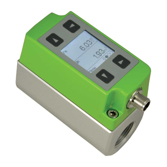
User Manual EE741 3 Product Description The EE741 flow sensor operates on the thermal mass flow measurement principle and is suitable for measuring the flow of compressed air and gases in pipelines. It can be used for measuring the consumption of compressed air, nitrogen, argon, oxygen, CO and other non-corrosive and non-flammable gases. -
Page 7: Modular Design
Once the gauge mounting block is built into the pipeline, the sensing unit can be installed and removed without disassemby of pipework. As a result, the EE741 is also ideal for temporary measurement at serveral mounting blocks. The sealing plug included in the scope of supply enables the normal operation of the compressed air system when the sensing unit is removed. -
Page 8: Functions
EE-PCS Product Configurator Software. Setting the Standard Conditions The standardized volume flow calculation is based on the standard conditions stored in the EE741 sensing unit. The factory setting for the standard conditions complies with DIN 1343: pn = 1013.25 mbar (14.7 psi);... -
Page 9: Analogue Output
Window mode Pulse Output (OUT 2) and Consumption Meter The EE741 flow sensor features an integrated meter with pulse output, which totalizes the consumption of compressed air or gas. With the display menu or the EE-PCS Product Configurator Software, the user can set: ▪... -
Page 10: Digital Interface
3.2.3. Digital Interface The EE741 is available in three different digital interface versions, with Modbus RTU, M-Bus or IO-Link interface. The Modbus RTU and M-Bus interface parameters can be accessed and changed with the help of the EE-PCS Product Configurator Software. -
Page 11: Installation Dimensions Gauge Mounting Block With Flanges
300 (11.8) 300 (11.8) Display The EE741 features an optional LC display showing the actual measured values and the overall consumption. The complete device setup and configuration can be performed with the control keys and intuitive, self explanatory menu navigation. -
Page 12: Mounting And Installation
The medium and the ambient conditions at the mounting location shall be non-condensing. ▪ In compressed air networks, the EE741 shall be installed after the air dryer. In the absence of a dryer, the EE741 shall be installed after the condensate separator and appropriate filters. -
Page 13: Installation Position
User Manual EE741 Installation Position The suitability of the following mounting positions must be taken into account for mounting the EE741 in the gauge mounting block or in the gauge mounting block with flanges. Mounting Position Vertical Horizontal, sensor upwards... -
Page 14: Inlet And Outlet Measurement Path
This can be accomplished by observing a minimum inlet and outlet path length, which depends on both the nature of disturbance and the pipe diameter. This applies to mounting the EE741 in the gauge mounting block as well as in the gauge mounting block with flanges. -
Page 15: Installation Of The Gauge Mounting Block
User Manual EE741 Installation of the Gauge Mounting Block 4.4. Gauge Mounting Block WARNING The gauge mounting block is symmetrical and can be installed in the pipeline irrespective of the flow direction. ▪ All connections must be properly sealed and checked for tightness. -
Page 16: Mounting The Sensing Unit Into The Gauge Mounting Block
User Manual EE741 Mounting the Sensing Unit into the Gauge Mounting Block WARNING Depressurize the pipeline before mounting or removing the sensing unit. In case the gauge mounting block has been operated without sensing unit, remove the sealing plug with a WAF 13 spanner. -
Page 17: Electrical Connection
User Manual EE741 5 Electrical Connection NOTICE Before electrical connections are made, the power supply must be turned off first. If not observed, the electronics can be damaged as a result. Only a qualified electrotechnical engineer may install the device. -
Page 18: Switch And Pulse Outputs Internal Circuit
User Manual EE741 5.1.1. Switch and Pulse Outputs Internal Circuit Switch and pulse outputs are NOT potential-free and include internal pull-down resistors (Fig. 16). OUT 1 OUT 2 Fig. 16 S witch / pulse output Inline Flow Sensor for Compressed Air and Gases | 18... -
Page 19: Setup And Configuration
The M-Bus (Meter-Bus) is a field bus for recording consumption data. Transmission runs serially on a reverse polarity protected two-wire line. The EE741 flow sensor as M-Bus adress requires a separate supply voltage. There is no prescribed specific topology (line or star) for the wiring. Normal phone cable of type J-Y(St)Y Nx2x0.8 mm can be used. -
Page 20: Modbus Rtu Register Map
User Manual EE741 Secondary addressing In addition to primary addressing, the EE741 flow sensor provides the option of secondary addressing. The fields of identification number, manufacturer, version and medium are used together as the secondary address. The exact sequence of the secondary addressing is described in detail in the M-Bus Standard: https://m-bus.com/assets/downloads/MBDOC48.PDF. - Page 21 /min 1519 MAX value standardized volume flow l/min 1521 MAX value standardized volume flow 1523 MAX value standardized volume flow SCFM 1525 1) Register number (decimal) starts from 1. 2) Register address (hexadecimal) starts from 0. Tab. 7 EE741 measured data registers Inline Flow Sensor for Compressed Air and Gases | 21...
- Page 22 ▪ Modbus protocol in the register 1 (0x00) and 2 (0x01). See Application Note Modbus AN0103 (available at www.epluse.com/ee741). The serial number as ASCII-code is located in read-only registers 1 - 8 (0x00 - 0x07). The firmware version is located in register 9 (0x08) (bit 15...8 = major release; bit 7...0 = minor release). The sensor name as ASCII-code is located in read-only registers 10 - 17 (0x09 - 0x11).
- Page 23 Sensor name 1) Register number (decimal) starts from 1. 2) Register address (hexadecimal) starts from 0. 3) Number of registers 4) For Modbus address and protocol settings see Application Note Modbus AN0103 (available at www.epluse.com/ee741). PLEASE NOTE Bus termination resistor: Bus termination is required for the last flow sensor in a Modbus RTU network. The 120 Ω termination resistor is located behind the blind of the USB port and can be switched on and off (see Fig.
-
Page 24: Io-Link
Process data input length 12 bytes IO-Link Revision Required masterport class Structure of process data input The Process Data Input (the measured data of EE741) is configurable and structured in the following order: Bit no. Process data input Measurand 1... -
Page 25: Usb Configuration Interface
Plug in the USB cable PLEASE NOTE For setup and configuration of the EE741 via USB interface it is necessary to install the EE-PCS Product Configuration Software on a personal computer. EE-PCS is available for free download at www.epluse.com/ee741. When an adjustment is performed using the EE-PCS, a suitable air velocity / temperature reference has to be used. -
Page 26: Measured Value Display
User Manual EE741 Measured Value Display Upon power on the display is in measuring mode and shows the measured values. Six measurands and a status page can be selected (Fig. 22 and Fig. 23). Abbreviations for measurands: Formula sign Measurand... - Page 27 User Manual EE741 Measuring mode Setup mode Output 1 Output 2 Pipe diameter Status DNxx Measurand 1 Display Measurand 2 Process param. Low-flow cut-off Measurand 3 Counter reading Measurand 4 Min/Max Measurand 5 Settings Measurand 6 Fig. 24 Display - menu navigation...
-
Page 28: Maintenance And Service
Explanation of the status led indicator General Recommendations It is recommended to calibrate the EE741 flow sensor on a yearly base. For use with polluted media, the sensing head should be cleaned periodically. Inline Flow Sensor for Compressed Air and Gases | 28... -
Page 29: Removal Of The Sensing Unit From The Gauge Mounting Block
User Manual EE741 Removal of the Sensing Unit from the Gauge Mounting Block WARNING Non-compliance with the product documentation may cause safety risk for people and the entire measurement installation. The pipeline must be depressurized before mounting or removing the sensing unit. -
Page 30: Accessories
User Manual EE741 9 Accessories For further information see datasheet Accessories. Description Code Inlet and outlet path BSP thread, stainless steel for gauge mounting block DN15 (1/2") HA070215 DN20 (3/4") HA070220 DN25 (1") HA070225 DN32 (1-1/4") HA070232 DN40 (1-1/2") HA070240 DN50 (2") - Page 31 DC PNP, max. 100 mA, V < 2.5 V, 10 kΩ pull-down drop Configurable: N/C or N/O, hysteresis, window Pulse output Totalizer (Consumption meter) Pulse length 0.02...2 s Digital Digital interface RS485 (EE741 = 1 unit load) Protocol Modbus RTU Factory settings 9 600 Baud, parity even, 1 stop bit, Modbus address 240 Supported Baud rates 600, 1 200, 2 400, 4 800, 9 600, 19 200, 38 400 and 57 600 Measured data types FLOAT32 and DOUBLE64 Protocol...
-
Page 32: Factory Setting Of Outputs For Dn15 / Dn20 / Dn25
User Manual EE741 10.1 Factory Setting of Outputs for DN15 / DN20 / DN25 Analogue output Switch output Minimum flow hysteresis mode shutdown Pipe Ø from Standardized volume flow [m DN15 0.15 0.07 DN20 0.25 0.12 DN25 0.35 0.17 Standardized volume flow [m /min] DN15 1.25 0.83 0.08 DN20 2.15 0.15... -
Page 33: Factory Settings Of The Outputs Dn32 / Dn40 / Dn50
User Manual EE741 10.2 Factory settings of the outputs DN32 / DN40 / DN50 Analogue output Switch output Minimum flow hysteresis mode shutdown Pipe Ø from Standardized volume flow [m DN32 0.55 0.25 DN40 0.45 DN50 Standardized volume flow [m /min] DN32 DN40 0.58 DN50 13.3 Standardized volume flow [l/min] DN32 5000 3300... -
Page 34: Works Certificate
User Manual EE741 10.3 Works Certificate Inline Flow Sensor for Compressed Air and Gases | 34... -
Page 35: Conformity
User Manual EE741 11 Conformity 11.1 Declarations of Conformity E+E Elektronik Ges.m.b.H. hereby declares that the product complies with the respective regulations listed below: European directives and standards. UK statutory instruments and designated standards. Please refer to the product page at www.epluse.com/ee741... - Page 36 User Manual EE741 Inline Flow Sensor for Compressed Air and Gases | 36...
- Page 37 User Manual EE741 Inline Flow Sensor for Compressed Air and Gases | 37...
- Page 38 User Manual EE741 Inline Flow Sensor for Compressed Air and Gases | 38...
- Page 39 User Manual EE741 Inline Flow Sensor for Compressed Air and Gases | 39...
- Page 40 T +39 02 2707 86 36 info.it@epluse.com E+E Elektronik Korea Ltd. T +82 31 732 6050 info.kr@epluse.com E+E Elektronik Corporation T +1 847 490 0520 info.us@epluse.com BA_EE741 | Version v1.9 | 02-2024 | 194408 © Copyright E+E Elektronik Ges.m.b.H. | All rights reserved.
Need help?
Do you have a question about the EE741 and is the answer not in the manual?
Questions and answers