Sign In
Upload
Manuals
Brands
E+E Elektronik Manuals
Accessories
EE741-N50
E+E Elektronik EE741-N50 Manuals
Manuals and User Guides for E+E Elektronik EE741-N50. We have
2
E+E Elektronik EE741-N50 manuals available for free PDF download: User Manual
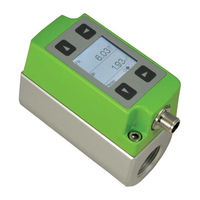
E+E Elektronik EE741-N50 User Manual (40 pages)
Inline Flow Sensor for Compressed Air and Gases
Brand:
E+E Elektronik
| Category:
Security Sensors
| Size: 7.53 MB
Table of Contents
Table of Contents
2
1 General Information
3
Explanation of Warning Notices and Symbols
3
Safety Instructions
4
General Safety Instructions
4
Intended Use
4
Mounting, Start-Up and Operation
5
Environmental Aspects
5
2 Scope of Supply
5
3 Product Description
6
Modular Design
7
Changing the Pipe Diameter
7
Functions
8
General
8
Analogue Output
9
Digital Interface
10
Dimensions
10
Installation Dimensions Gauge Mounting Block with Flanges
11
Display
11
4 Mounting and Installation
12
Choosing the Appropriate Mounting Location
12
Process Pressure
12
Installation Position
13
Inlet and Outlet Measurement Path
14
Installation of the Gauge Mounting Block
15
Operating the Pipeline Without Sensing Unit
15
Mounting the Sensing Unit into the Gauge Mounting Block
16
5 Electrical Connection
17
Connection Diagram
17
Switch and Pulse Outputs Internal Circuit
18
6 Setup and Configuration
19
Digital Interface
19
M-Bus (Meter-Bus)
19
Modbus RTU Register Map
20
IO-Link
24
USB Configuration Interface
25
7 Display
25
Measured Value Display
26
Display Menu
26
8 Maintenance and Service
28
Error Messages
28
General Recommendations
28
Removal of the Sensing Unit from the Gauge Mounting Block
29
Cleaning the Sensing Head
29
Repairs
29
9 Accessories
30
10 Technical Data
30
Factory Setting Of Outputs For Dn15 / DN20 / DN25
32
Factory Settings Of The Outputs Dn32 / DN40 / DN50
33
Works Certificate
34
11 Conformity
35
Declarations of Conformity
35
FCC Part 15 Compliance Statement
35
ICES-003 Compliance Statement
35
Advertisement
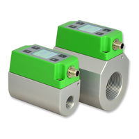
E+E Elektronik EE741-N50 User Manual (29 pages)
Inline Flow Sensor for Compressed Air and Gases
Brand:
E+E Elektronik
| Category:
Accessories
| Size: 5.72 MB
Table of Contents
Table of Contents
3
1 General
4
Explanation of Symbols
4
Safety Instructions
4
Intended Use
4
Mounting, Start-Up and Operation
5
Environmental Aspects
5
2 Scope of Supply
5
3 Product Description
6
Modular Design
7
Changing the Pipe Diameter
7
Functions
8
General
8
Analogue Output
8
Digital Interface
9
4 Mechanical Installation
10
Installation Dimensions
10
Installation Dimensions Gauge Mounting Block
10
Installation Dimensions Gauge Mounting Block with Flanges
10
Choosing the Appropriate Mounting Location
11
Process Pressure
11
Installation Position
11
Inlet and Outlet Measurement Path
12
Installation of the Gauge Mounting Block
13
Gauge Mounting Block
13
Gauge Mounting Block with Flanges
13
Operating the Pipeline Without Sensing Unit
13
Mounting the Sensing Unit Unit into the Gauge Mounting Block
14
5 Electrical Installation
15
Connection Diagram
15
Switch and Pulse Outputs Internal Circuit
15
Digital Interface
16
M-Bus (Meter Bus)
16
Modbus RTU
17
IO-Link
19
USB Configuration Interface
20
6 Display
20
Measured Value Display
21
Display Menu
21
7 Error Messages
23
8 Maintenance
23
Removing the Sensing Unit from the Gauge Mounting Block
24
Cleaning the Sensing Head
24
9 Ordering Guide for Accessories
24
10 Technical Data
25
10.1 Factory Settings of the Outputs for DN15 / DN20 / DN25
26
10.2 Factory Settings of the Outputs DN32 / DN40 / DN52
27
10.3 Works Certificate
28
Advertisement
Related Products
E+E Elektronik EE741 Series
E+E Elektronik EE245
E+E Elektronik EE600
E+E Elektronik EE100EX
E+E Elektronik EE211
E+E Elektronik EE300Ex-M3
E+E Elektronik EE33
E+E Elektronik EE800
E+E Elektronik EE300Ex-M1
E+E Elektronik EE240
E+E Elektronik Categories
Transmitter
Accessories
Measuring Instruments
Temperature Controller
Control Unit
More E+E Elektronik Manuals
Login
Sign In
OR
Sign in with Facebook
Sign in with Google
Upload manual
Upload from disk
Upload from URL