Table of Contents
Advertisement
Quick Links
USER'S GUIDE
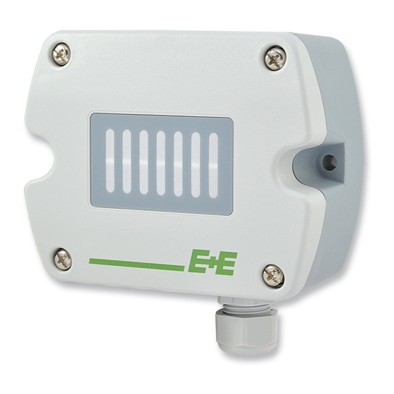
EE820 – CO
Sensor for Demanding Applications
2
SCOPE OF SUPPLY
•
EE820 Sensor according to ordering guide
•
Mounting set (screws and rowl plugs / screw anchors)
•
Cable gland (only for EE820-HVxxxE1xxx with cable gland)
•
Mating M12x1 connector for self assembly (only for EE820-HVxAxE9xxx with M12x1 plug)
•
Two self-adhesive labels for configuration changes (see user guide at www.epluse.com/relabeling)
•
Quick Guide - For EE820 with M12 plug and EE820 with RS485 output
•
Test report according to DIN EN 10204 – 2.2
ACCESSORIES / SPARE PARTS
ACCESSORIES
(see datasheet "Accessories"):
USB configuration adapter
Product configuration software
Mating M12x1 connector for self assembly
Connection cable M12x1 socket - flying leads
•
1.5 m
(3.3 ft)
•
5 m
(16.4 ft)
•
10 m
(32.8 ft)
Protective cap for female M12 connectors
Protective cap for male M12 connectors
Power supply adapter
SPARE PARTS:
Forced air circulation module, without cover
Cover complete with filter and mounting screw
CAUTION
•
The sensor shall not be exposed to extreme mechanical or thermal stress.
•
For use in polluted, dirty environment is essential to close tightly the sensor cover as well as the cable glad or conduit
adapter in order to avoid pollution ingress into the enclosure.
•
This device is not appropriate for safety, emergency stop or other critical applications where device malfunction or failure could
cause injury to human beings.
DIMENSIONS
90
mm
±0.3
3.54
"
±0.11
5mm
0.2"
19mm
0.75"
HA011066
EE-PCS
(free download: www.epluse.com/EE820)
HA010707
HA010819
HA010820
HA010821
HA010781
HA010782
V03
EE820-FAC (HA011302)
EE820-COVER (HA011303)
FOR CONDUIT
INSTALLATION
CABLE GLAND M16x1.5
M12x1 Plug
Mating M12x1 connector for self assembly is
included in the scope of supply
Advertisement
Table of Contents

Related Manuals for E+E Elektronik EE820


Summary of Contents for E+E Elektronik EE820
- Page 1 • Two self-adhesive labels for configuration changes (see user guide at www.epluse.com/relabeling) • Quick Guide - For EE820 with M12 plug and EE820 with RS485 output • Test report according to DIN EN 10204 – 2.2 ACCESSORIES / SPARE PARTS ACCESSORIES (see datasheet “Accessories”):...
-
Page 2: Connection Diagram
EE820 with M12 plug does not require any wiring inside the device. The external mounting holes allow the device to be mounted without opening the front cover. The mating M12x1 cable plug for self assembly is included in the scope of supply. Please see EE820 data sheet for optional M12 plugs and cables. - Page 3 1) for performance according to specification SETUP AND ADJUSTMENT The EE820 is ready to use and does not require any configuration by the user. The factory setup of EE820 corresponds to the type number ordered. For ordering guide please see data sheet at www.epluse.com/EE820.
- Page 4 Important: • After changing the factory setup (output signal and/or output scale) the original type number on the EE820 identification label loses its validity; it does not match any longer the device setup. • The return to factory setup function of EE-PCS restores the original adjustment/calibration of the device, but does not affect the user setup for output signal and output scale.
- Page 5 In a polluted environment, the filter on the front cover of EE820 might get clogged in a long run. This is more likely to happen for the EE820 with forced air circulation.
- Page 6 For installing the new EE820-FAC: • Observe the position of the A and B restraints in the cover and of the corresponding cut-outs 1 and 2 in the EE820-FAC board. • Insert first the EE820-FAC into the B restraints. Than press the EE820-FAC as in the picture below, till in snaps into the A restraints.
- Page 7 • Fix the cover with the 4 bayonett screws D. FCC notice: This equipment has been tested and found to comply with the limits for a Class B digital device, pursuant to part 15 of the FCC Rules. These limits are designed to provide reasonable protection against harmful interference in a residential installation.
Need help?
Do you have a question about the EE820 and is the answer not in the manual?
Questions and answers