Table of Contents
Advertisement
Advertisement
Table of Contents

Related Manuals for Novusun CNC NVCM Series


Summary of Contents for Novusun CNC NVCM Series
- Page 1 百年品质,值得信赖 —— 您的产品名称 MACH3 USB port 6 axis Controller Card NVCM Manual...
-
Page 2: Table Of Contents
Manual of NVCM 请在这里输入您的公司名称或产品名称 Contects Chapter 1. Introduction ..........................- 1 - 1.1 Product Introduction ..........................- 1 - 1.2 Products specification ..........................- 1 - 1.3 Products Appearance and size ........................ - 2 - 1.4 substantival explanation ......................... - 3 - 1.5 Noting and Waring .......................... -
Page 3: Chapter 1. Introduction
Introduction 1.1 Product Introduction Novusun CNC has engaged in the Numerical control industry for 7 years, specialized in the research, development and production of various CNC controller systems with high quality and high reliability. We produce the Brushless DC motor, Stepper motor driver, and also 1 to 6 axis CNC motion controllers.。... -
Page 4: Products Appearance And Size
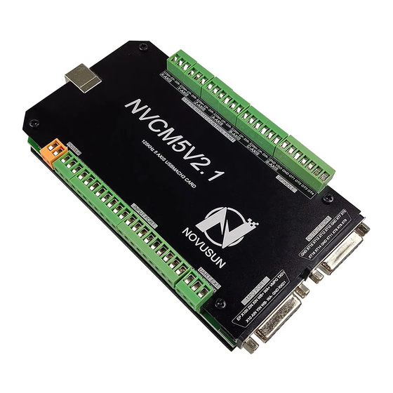
Manual of NVCM 1.3 Products Appearance and size NVCM motion controller is with the sealed open structure, there are 4pcs setting holes at the bottom. We can fix 2pcs 3mm diameter holes at the cabinet, and install the controller into the cabinet.The controller appearance as the Figure 1-1 and Figure 1-2 show: The products overall size is 150mm*84mm*20mm ;... -
Page 5: Substantival Explanation
Manual of NVCM Figure1-2. The other side of NVCMand installation dimensions 1.4 substantival explanation When operate the NVCM, where will be a lot of English abbreviation, now we list all . FRO: Feeding adjust: During the operating process, the F value already set, and need to adjust the current feeding speed, then we can adjust FRO value to realize it. -
Page 6: Noting And Waring
Manual of NVCM B axis Coordinate C axis Coordinate Ready:ReadyMode.In the mode we can do any operation,include processing or values modification or starting 2nd mode. Reset: Reset mode.In this mode,it should stop every operation. “Step”:Manual Step Mode. Every axis candonduct the manual step operation at this mode. MPG: MPG mode.Every axis can conduct the MPG operation at this mode. -
Page 7: Chapter 2. Connection
Manual of NVCM Chapter 2. Connection 2.1 Device Power supply Solution The power supply solution in the field of the Industrial automation is always very complicated, there is a lot of the GND, now we descript the structure of the power supply as below: The power supply structure as the Figure 2-1,main power supply input and MPG module and stepper control output module are common GND, Limited and Estop input module and Spindle... -
Page 8: Product Connection Define And Method
Manual of NVCM 2.2 Product connection define and method Figure2-2. Product wiring section and interface summary As the Figure 2-2 showed, the connection of the controller includes power supply interface, USB connection interface, Stepper/Servo control output interface, spindle control output interface, Estop and limited switch and tool setting input interface and so on. - Page 9 Manual of NVCM terminal is "-". 2.2.3 Limit/Home/Estop/Probe input port As the Figure 2-2 showed, Marked No. 3 position is the input port. they are the optical isolated Input interface.The silkprint INP1 INP2 GND INP3 INP4 INP5 INP6 INP7 INP8 INP9 GND IN10 IN11 IN12 IN13 IN14 IN15 IN16 GND 12V on the board connect to PIN1-16 of the mach3.
- Page 10 Manual of NVCM 3 lines Proximity Switch connection Figure 2-5,brown cable for Proximity switch connect with 12V,Black cable connect channel, blue cable connect with GND1. Only support NPN 3lines proximity switch. Figure2-5. NPN 3 lines Proximity Switch connection drawing 2.2.4 Serial expansion interface As the Figure 2-2 showed, Marked No.
- Page 11 Manual of NVCM WHB+ B phase negative of the encoder X axis select input Z axis select input X100IN 100 rate select input Estop port R1IN RXD of Serial port(only for NVMPG) Ground and common end WHA- A phase positive of the encoder WHB- B phase negative of the encoder Y axis select input...
- Page 12 Manual of NVCM Mark Definition Output5 Output7 Ground and common end XT10 Output10 XT12 Output12 XT13 Output13 XT15 Output15 Ground and common end Output6 Output8 Output9 XT11 Output11 Ground and common end XT14 Output14 XT16 Output16 ☞Output in mach3 should be configured to PORT 2 Table 2-2.
- Page 13 Manual of NVCM Figure2-7. spindle control output and inverter connection VSO real output voltage=10V*s spindle setting speed/max spindle speed.Forexample,if max spindle speed is 24000,current spindle speed is S=18000,so the VSO output voltage=10*18000/24000=7.5V. Max. spindle speed setting ports as showed sa Figure 2-4,open it from Pulley from Menu config.
- Page 14 Manual of NVCM Figure2-8. Max spindle speed setting position 2.2.8 Stepper motor port. As the Figure 2-2 show, The marked No. 8 are 6 axis stepper motor controller port. They are X/Y/Z/A/B/C from left to right. Each axis's pin is defined as COM+/CP-/DIR- from left to right. Wiring method see as figure 2-9.
-
Page 15: Chapter 3. Software Installation
Manual of NVCM Chapter 3. Software Installation 3.1 MACH3 Install MACH3 installation, registration, and USB plug-ins. See as Figure 3-1 Figure3-1. MACH3 soft installation First run the installation Mach3Version3.043.066 .Into the first page. See as Figure 3-2. - 13 -... - Page 16 Manual of NVCM Figure3-2. MACH3 installation process 1 Click Next and then enter the page shown in Figure 3-3 Figure3-3. installation process Select I agree and click Next,See as Figure 3-4. - 14 -...
- Page 17 Manual of NVCM Figure3-4. MACH3 installation process Select the installation path, click Next (it can be installed on any disk, and recommended to install the C drive or the D drive) See as Figure 3-5 Figure3-5. MACH3 installation process Click Next until completion. Then restart the computer. - 15 -...
-
Page 18: Plugin Install
Manual of NVCM 3.2 Plugin Install Copy the file NOVUSUN.DLL to X:/mach3/plugin, X is installation disk of mach3. - 16 -... -
Page 19: Chapter 4. Setting Of Software
Manual of NVCM Chapter 4. Setting of software 4.1 Open software Double-click the mach3mill . Start mach3 software. We enter plugin select dialog box. See as Figure 4-1. You should copy NOVUSUN.DLL to plguin folder first, then you can see this dialog box. Plguin select dialog box Figure4-1. -
Page 20: Software Common Settings
Manual of NVCM Open mach3 software Figure4-2. 4.2 Software Common settings 4.2.1 Motor operating parameters setting Figure4-3. Motor operating parameter setting menu entry See as Figure 4-2.From submenu “motor tuning” of the menu “config” into the motor - 18 -... - Page 21 Manual of NVCM parameter settings dialog. See as Figure 4-3 Figure4-4. Motor operating parameter settings dialog The parameters are defined as follows: teps per Pulse equivalent ,it is number of pulses required with axial movement 1mm, This : can be calculated by lead screw pitch and motor drive segment. Such as pitch 2.5mm,2-phase motor 8 segments, Calculation method is 8*200/2.5=640 。...
- Page 22 Manual of NVCM Figure4-5. Port setting intry See as Figure 4-5 , Click the sub-menu “ports and pins” of menu “Config” into Port Settings dialog box. Figure4-6. Pin&Port Dialog The sub-pages you need to set include “Motor Outputs”, “Input Signals”, “Output Signals” and “Spindle Setup”.
- Page 23 Manual of NVCM To make the Z axis to the same direction, Z axis’s “Dir low” should be set to”√”.Other axes’s should be set as system need. Figure4-7. Stepper motor port settings dialog Click “Input Signals” Into the input signal settings page. See as Figure4-8 - 21 -...
- Page 24 Manual of NVCM limited Input Settings dialog Figure4-8. Here you can configure according to your actual needs the corresponding function. Optional Function include XYZABC6axis’s Upper and lower limit 、 XYZABC6axis’s HOME point. We set upper limit and home of XYZA to 3456 corresponding IN3IN4IN5IN6 of the board. Figure4-9.
- Page 25 Manual of NVCM Spindle Settings dialog Figure4-10. Here we can configure the spindle rotates CW Reverse 、 CCW Mist Flood pin, See as 、 、 Figure4-10 , They have been configured as 1 2 3 4. Corresponding to output#1~output#4 in 、...
-
Page 26: Chapter 5. Using Of Software
Manual of NVCM Chapter 5. Using of software 5.1 Set Machine Coordinate system Firstly Open the software,as the drawing 5-1 shows,at this time,the software can operate the machine movements,but before the setting machine coordinate system,there is no connection between the software and machine.So first step is to set the machine coordinate system. Figure5-1. - Page 27 Manual of NVCM orginal point direction, × means searching original point at negative direction; √ means searching original points at the positive direction.As the pincture 5-3 shows,X axis’s original position is at the negative direction,Y and Z’s original points are at the positive direction. Figure5-2.
-
Page 28: Set Workpiece Coordinate System
Manual of NVCM As Figure 5-3 shows,this page also can set machine soft limit points,Soft Max is positive direction soft limited points,soft Min is negative direction soft limited points.The soft limited points values is according the references to the machine coordinate system,so as this example shows,Y and Z axis’s max value is 0,all the effective coordinate data is less than 0.As the Figure shows,according to our current request,we set our XYZ axis soft limited points area as [0,270] [-390,0] [-100,0]. - Page 29 Manual of NVCM one or more workpiece coordinate system. 1 、 Move to current working piece 0 point Firstly hold down the material,use keyboard or pendant to move tool tip at the 0 point,so this 0 point is the working piece 0 point,it related with the working G code file,so the user must be very familiar to his own working G code.As our example shows,the 0 point is on the center of the working piece surface,so we just move the tool tip to this position.
-
Page 30: Open G Code File And Run
Manual of NVCM Figure5-6. Main Screen after ZERO all axis 5.3 Open G code file and run As Figure 5-7 shows,press “load G code” botton at the main page or open “Load G code” at main menu “File”,open your G code.It displayed as Figure 5-8 showing,then press button “cycle start”... - Page 31 Manual of NVCM Figure5-7. Press Load G-Code and open your G code Figure5-8. After opening G code,press “Cycle Start” and start to work - 29 -...
Need help?
Do you have a question about the NVCM Series and is the answer not in the manual?
Questions and answers