
Related Manuals for Novusun CNC NVUM


Summary of Contents for Novusun CNC NVUM
- Page 1 百 年品质,值得信赖 —— 您的产品名称 MACH3 USB Card NVUM Manual +7(495) 407-01-02 +7(495) 407-01-02 www.zetek.ru www.zetek.ru www.shop.zetek.ru www.shop.zetek.ru...
- Page 2 Chapter 3. Software Installation ........................- 20 - 3.1 MACH3 Install ............................- 20 - 3.2 MACH3 Registration ...........................- 23 - 3.3 NVUM Plug-in installation........................- 23 - Chapter 4. Setting of software ........................- 24 - 4.1 Open software ............................- 24 - 4.2 Software Common settings ........................- 25 - Chapter 5.
-
Page 3: Chapter 1. Introduction
Introduction 1.1 Product Introduction Novusun CNC has engaged in the Numerical control industry for 7 years,specialized in the research,development and production of various CNC controller systems with high quality and high reliability.We produce the Brushless DC motor,Stepper motor driver,and also 1 to 6 aixs CNC motion controllers.。... - Page 4 Manual of NVUM can support 3-6 axis stepper systems,200KHz pulse output for every axis; ARM motion control chip; main device is 12V-32VDC power supply input,current should higher than 0.5A; Compatible with MPG input,support the digital display MPG from our company。...
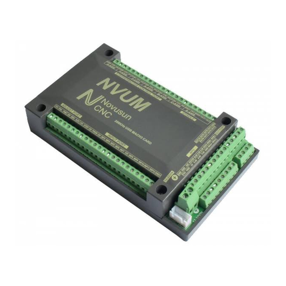
- Page 5 The other side of NVUMV1.1and installation dimensions 1.4 substantival explanation When operate the NVUM,where will be a lot of English abbreviation,now we list all of them for your kindly references: FRO:Feedingadjust:During the operating process,the F value already set,and need to adjust the current feeding speed, then we can adjust FRO value to realize it.
- Page 6 Manual of NVUM Current Speed S#=setting S*SRO. SRJ:speed adjust manually During the operating process,as the manual speed already set,and we need to adjust the current speed,and impossible to fix the value during it is working,then we can revise the SRJ value to realize it.
- Page 7 Manual of NVUM 1.5 Noting and Waring Free from exposure to the electronics without waterproof function.Please environment as dry as possible. This is the icon. Wiring warning, the IO input terminal of this equipment support the equipment with source switch (such as Inductive proximity switch.)When using such kind of switch, attention please: avoid the +terminal and –terminal of...
- Page 8 If connect an external relay,need to output GND to refer to,and give the relay an external power supply. Figure2-1. Power supply structure of NVUM +7(495) 407-01-02 www.zetek.ru - 6 -...
- Page 9 Manual of NVUM 2.2 Product connection define and method Figure2-2. Product wiring section and interface summary As the Figure 2-2 showed,the connection of the controller includes power supply interface, USB connection interface, MPG interface, Stepper/Servo control output interface, spindle control output interface, Estop and limited switch and tool setting input interface and so on.
- Page 10 Manual of NVUM Pin mark Axis Definition common anode +5V Commom+ COM+ X axis Pulse output- for X axis CPX- Directrion output- for X axis DIX- axis Pulse output- for Y axis CPY- axis Directrion output- for Y axis DIY-...
- Page 11 Manual of NVUM Figure2-3. Stepper driver connection 2.2.2 Spindle control output We define the interface from left are: GND1(Output GND),VSO(0-10V adjustable speed output),INDEX(spindle speed feedback input),OUT1(common output port 1),OUT2(common output port 2),. Take Nowforeuer inverter as the example. Spindle control output and the inverter connection showed as Figure 2-4.If ACM and DCM are closed,only need to connect one port.
- Page 12 Manual of NVUM Figure2-4. spindle control output and inverter connection VSO real output voltage=10V*s spindle setting speed/max spindle speed.Forexample,if max spindle speed is 24000,current spindle speed is S= 18000,so the VSO output voltage=10*18000/24000=7.5V. Max. spindle speed setting ports as showed sa Figure 2-5,open it from Pulley from Menu config.The current spindle speed can be set by S directive or Mach 3 spindle setting speed module.
- Page 13 Manual of NVUM 2.2.3 Common IO output interface Common IO output include OUT1,OUT2 on the spindle interface,totally 10 ports IO output,open drainoutput,internal structure as Figure 2-6: Figure2-6. OUT1-OUT10 internal structure Now just make a switch between OUTX(X=1-10) and GND,to control the relay output,theconection as the Figure 2-6.External power supply need to accord with the relay...
- Page 14 Manual of NVUM Figure2-7. OUTX connect with external relay method 2.2.4 MPG connection The MPG port totally have 18 wiring terminals, and the reference of eachwiring terminal definition is table 2-2. The reference of corresponding relation between system and MPG wiring is table 2-3 and table 2-4.
- Page 15 MPG B Phase differential Input Positive WHB+ MPG A Phases Negative MPG A Phase differential Input Negative WHA- MPG B Phases Negative MPG B Phase differential Input Negative WHB- Table 2-2. NVUM on MPG’s define and explaination +7(495) 407-01-02 www.zetek.ru - 13 - www.shop.zetek.ru...
- Page 16 +5V-W Table 2-3. Connection between Differential MPG and NVUM Note: It you want to use the single-terminal MPG (namely there is no A-B-MPG), please look at the wiring table, the table 2-4 for reference. As for the unlisted one, please take the differential MPG wiring mode.
- Page 17 STOP,12V,PROB,12V,INP3,INP4,INP5, INP6,INP7,12V,INP8,INP9,INP10,INP11,INP12,GND.Here STOP is INPUT1 ,and PROB is INPUT2. Internal structure Figure of Input interface see as Figure 2-8 ESTOP connect with NVUM see as Figure 2-9.Probe connect see as Figure 2-10 +7(495) 407-01-02 www.zetek.ru - 15 - www.shop.zetek.ru...
- Page 18 Manual of NVUM Figure2-8. Internal structure drawing of Input interface Figure2-9. Estop input connection +7(495) 407-01-02 www.zetek.ru - 16 - www.shop.zetek.ru...
- Page 19 Manual of NVUM Figure2-10. Tool Setting Connection Drawing 2 lines Proximity Switch/ordinary frettingswitch drawing see as Figure 2-11 Figure2-11. 2 lines Proximity Switch/ordinary frettingswitch drawing 3 lines Proximity Switch connection Figure 2-12,brown cable for Proximity switch connect with 12V,Black cable connect channel,blue cable connect with GND1.
- Page 20 Manual of NVUM Only support PNP 3lines proximity switch. Figure2-12. PNP 3 lines Proximity Switch connection drawing 2.2.8 Parameter adjust interface By this adjust interface,user can use a muti-position switch and adigital potentionmeter(simple encoder) to modify FRO,SROand SJR.Wiring method see as figure2-13 simple encoder's COM A B connect to 12V/FHA/FHB,and muti-position switch connect to 12V SRO SJR.If 12Vdon't connect to SRO or SJR,current effective parameter is FRO, if 12V connect...
- Page 21 Manual of NVUM Figure2-13. Parameter adjust port 2.2.9 USB Port As the Figure 2-2 show,The marked No. 9 port is USB communication port,NVUM communicate with mach 3 through it. +7(495) 407-01-02 www.zetek.ru - 19 - www.shop.zetek.ru...
-
Page 22: Software Installation
Manual of NVUM Chapter 3. Software Installation 3.1 MACH3 Install When you purchase our product, we will supply which contains the MACH3 installation,, and US B plug-ins. See as Figure 3-1 Figure3-1. MACH3 soft installation First run the installation Mach3Version3.043.066 .Into the first... - Page 23 Manual of NVUM Figure3-2. MACH3 installation process 1 Click Next and then enter the page shown in Figure 3-3 Figure3-3. installation process Select I agree and click Next,See as Figure 3-4. +7(495) 407-01-02 www.zetek.ru - 21 - www.shop.zetek.ru...
- Page 24 Manual of NVUM Figure3-4. MACH3 installation process Select the installation path, click Next (it can be installed on any disk, and recommended to install the C drive or the D drive) See as Figure 3-5 Figure3-5. MACH3 installation process Click Next until completion. Then restart the computer.
- Page 25 Manual of NVUM 3.2 MACH3 Registration Copy the file Mach1Lic.dat in The CD-ROM to mach3 installation path (eg C:/MACH3). NVUM Plug-in installation Copy the file NVUM.dll to X:\Mach3\PlugIns,X is the disk where the soft is installed. +7(495) 407-01-02 www.zetek.ru - 23 -...
-
Page 26: Open Software
Choose our plugin NVUM_Novusun-PlugIn---Ver-2.0a。Then press OK. If you do not want to the dialog box appear again next time, you can select Don’t ask me this again.If connect successfully,Status bar will show “NVUM device is connected to your computer”. See as Figure4-2. - Page 27 Manual of NVUM 4.2 Software Common settings 4.2.1 Check NVUM plugin Click config plugins to input PluginConfig,you can seeNVUM. See as Figure4-4. Figure4-3. Input Config plugins Figure4-4. MVUM Plugin - 25 - +7(495) 407-01-02 www.zetek.ru www.shop.zetek.ru...
- Page 28 Manual of NVUM 4.2.2 Motor operating parameters setting Figure4-5. Motor operating parameter setting menu entry See as Figure 4-5.From submenu “motor tuning” of the menu “config” into the motor parameter settings dialog. See as Figure 4-6 Figure4-6. Motor operating parameter settings dialog The parameters are defined as follows: Steps per:Pulse equivalent ,it is number of pulses required with axial movement 1mm, This...
- Page 29 Manual of NVUM motor 8 segments, Calculation method is 8*200/2.5=640。 Velocity:The speed is the axial velocity, Units is mm/s,Recommended settings 1500. Acceleration:Units is mm/s2,Recommended settings 200. Step Pulse:Step Pulse Cannot be set, it’s 2.5us in default. Dir Pulse:. Dir Pulse Cannot be set, it’s 2.5us in default.
- Page 30 Manual of NVUM Figure4-8. Pin&Port Dialog The sub-pages you need to set include “Motor Outputs”, “Input Signals”, “Output Signals” and “Spindle Setup”.First Click to enter “Motor Outputs”. This page is to select the stepper motor control pin. Because our usbmach3 interface board stepper motor signals are fixed, So here only need to Select, no need to select the specific pin.
- Page 31 Manual of NVUM limited Input Settings dialog Figure4-10. Here you can configure according to your actual needs the corresponding function. Optional Function include XYZABC6axis’s Upper and lower limit、XYZABC6axis’s HOME point. Figure4-11. Estop Probe and index Setting dialog PROBE、ESTOP and Spindle speed back index Setting see as Figure 4-11,PIN of index...
- Page 32 Manual of NVUM should be set to 0,and probe’s pin number is 2,estop’s pin number is 1. Click “Output Signals” to enter the Output signal setting page. See as Figure 4-12 Output Signal Setup dialog Figure4-12. Note that the output signal number from 1-16. Because there is an overlap with the input signal, We set output signals to the port 2.See as Figure4-12, PORT # All output signal is set to...
- Page 33 Manual of NVUM Figure4-14.output#1~output#6 in Output Signal Setup dialog can be Configured into these 4 signals. Here we only configure CW and CCW.CW is controlled by OUT1 and CCW is controlled by OUT2. Here we note correspondence between 2 page. Please select “use spindle motor output”...
- Page 34 Manual of NVUM Chapter 5. Using of software 5.1 Set Machine Coordinate system Firstly Open the software,as the drawing 5-1 shows,at this time,the software can operate the machine movements,but before the setting machine coordinate system,there is no connection between the software and machine.So first step is to set the machine coordinate system.
- Page 35 Manual of NVUM orginal point direction, × means searching original point at negative direction; √ means searching original points at the positive direction.As the pincture 5-3 shows,X axis’s original position is at the negative direction,Y and Z’s original points are at the positive direction.
- Page 36 Manual of NVUM As Figure 5-3 shows,this page also can set machine soft limit points,Soft Max is positive direction soft limited points,soft Min is negative direction soft limited points.The soft limited points values is according the references to the machine coordinate system,so as this example shows,Y and Z axis’s max value is 0,all the effective coordinate data is less than 0.As the Figure...
- Page 37 Manual of NVUM one or more workpiece coordinate system. 1、Move to current working piece 0 point Firstly hold down the material,use keyboard or pendant to move tool tip at the 0 point,so this 0 point is the working piece 0 point,it related with the working G code file,so the user must be very familiar to his own working G code.As our example shows,the 0 point is on the center of the...
- Page 38 Manual of NVUM Figure5-6. Main Screen after ZERO all axis 5.3 Open G code file and run As Figure 5-7 shows,press “load G code” botton at the main page or open “Load G code” at main menu “File”,open your G code.It displayed as Figure 5-8 showing,then press button “cycle start”...
- Page 39 Manual of NVUM Figure5-7. Press Load G-Code and open your G code Figure5-8. After opening G code,press “Cycle Start” and start to work +7(495) 407-01-02 www.zetek.ru www.shop.zetek.ru...
Need help?
Do you have a question about the NVUM and is the answer not in the manual?
Questions and answers