Table of Contents
Advertisement
Quick Links
Advertisement
Table of Contents

Related Manuals for Novusun CNC NCH02


Summary of Contents for Novusun CNC NCH02
- Page 1 百年品质,值得信赖 —— 您的产品名称 5 axis Montion Controller System NCH02 Manual...
-
Page 2: Table Of Contents
Chapter 2. Connection ........................... - 6 - 2.1 Device Power supply Solution ....................... - 6 - 2.2 Hand control NCH02 KEYBOARD's Definition .................. - 7 - 2.3 Port Definition and connection ......................- 9 - Chapter 3. Software & Config ........................- 18 - ... -
Page 3: Chapter 1. Introduction
CNC motion controllers.。 NCH02 is the 5 axis motion controller we spend 2 years to design. NCH02 is a CNC system without computer. Only need a U-disk within G-CODE file, NCH02 can read the G file and run the G file. -
Page 4: Products Appearance And Size
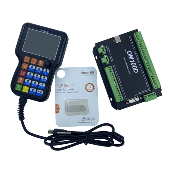
19 user key; 1.3 Products Appearance and size The Hand control system NCH02 appearance as the Figure 1-1 show: The host system NCD02 appearance as the Figure1-2. The Hand control system NCH02 overall size is 168mm*108mm*30mm ; The host system NCD02 overall size is 100mm*70mm*23.5mm Figure1-1. - Page 5 Manual of NCH02 The host system Figure1-2. NCD02 appearance and size Figure1-3. NCH02 with NCD02 - 3 -...
-
Page 6: Substantival Explanation
Manual of NCH02 1.4 substantival explanation When operate the NCH02, where will be a lot of English abbreviation, now we list all of them for your kindly references: FRO: Feeding adjust: During the operating process, the F value already set, and need to adjust the current feeding speed, then we can adjust FRO value to realize it. -
Page 7: Noting And Waring
Manual of NCH02 modification or starting 2nd mode. Reset: Reset mode.In this mode,it should stop every operation. “Step”:Manual Step Mode. Every axis candonduct the manual step operation at this mode. MPG: MPG mode.Every axis can conduct the MPG operation at this mode. -
Page 8: Chapter 2. Connection
Manual of NCH02 Chapter 2. Connection 2.1 Device Power supply Solution The power supply solution in the field of the Industrial automation is always very complicated, there is a lot of the GND, now we descript the structure of the power supply as... -
Page 9: Hand Control Nch02 Keyboard's Definition
Manual of NCH02 2.2 Hand control NCH02 KEYBOARD's Definition 2.2.1 KEYBOARD's Definition KEYBOARD's Definition see as Table 2-1 Location Icon Name Function R 1 C 1 PAGE L 1:Page left R 1 C 2 PAGE R 1:Page right R 1 C 3 CANCEL 1:Cancel;2:Sign out... - Page 10 Manual of NCH02 R 4 C 1 SPINDLE 1:Start and Stop Spindle R 4 C 2 1:A axis manual reverse;2:Probe;3:Number 1;4: Move left R 4 C 3 1:Y axis manual forward;2:Select Y axis;3:Number 2;4:Move up R 4 C 4 1:...
-
Page 11: Port Definition And Connection
MPG port, spindle port and stepper motor control port. The detailed description of these functional modules and interfaces is described below. 2.3.1 USB port As Figure 2-2 showed,No.1 terminal block is USB port, you can connect with NCH02 through this interface. 2.3.2 Main power supply port As the Figure 2-2 show, The marked No. - Page 12 Manual of NCH02 As the Figure 2-2 showed, Marked No. 3 position is the limited /home input port. they are the optical isolated Input interface. The input interface is a 11P 3.81 direct insertion terminal interface, shown Figure shell...
- Page 13 Manual of NCH02 Figure2-5. input interface serial number IN3 and 2 line proximity switch / common switch limit input wiring diagram 3 lines Proximity Switch connection Figure 2-13,brown cable for Proximity switch connect with 12V,Black cable connect channel, blue cable connect with GND1.
- Page 14 Manual of NCH02 Figure2-7. NPN 3 line Proximity switch wiring 2.3.4 Output port As Figure 2-2 showed,No.4 switch is Output port, The interface is an open-ground interface. The internal structure refers to figure 2-8, which can be absorbed not more than 50mA current.
- Page 15 Manual of NCH02 Figure2-8. the internal structure of the general output interface The relay with a absorption current of no more than 50mA can be driven directly. If it's more than 50mA, and it is recommended to use a current amplification current, such as the use of a ULN2803 chip.
- Page 16 Manual of NCH02 This card connect with MPG by this port. The port definition see as table 2-2 Mark Definition T1OUT TXD of Serial port VMPG Power supply + for MPG(5V) WHA+ A phase positive of the encoder WHB+...
- Page 17 Manual of NCH02 common end configured to forward and reverse. Figure2-11. spindle port definition and connection 2.3.7 Stepper motor port As Figure 2-2 showed,No.7 port is stepper motor port, which is define as X/Y/Z/A/B. Each axis is define as COM+/CP-/DIR-. They are Common/Pulse-/Direction-. The connection method with the stepper motor driver see as Figure 2-12.
- Page 18 Manual of NCH02 Figure2-12. NCD02 Connect with stepper motor driver The above detailed description of the NCD02 module definition and connection mode, NCD02's integrated wiring diagram reference figure 2-13. - 16 -...
- Page 19 Manual of NCH02 NCD02 and NCH02 integrated wiring diagram Figure2-13. - 17 -...
-
Page 20: Chapter 3. Software & Config
Manual of NCH02 Chapter 3. Software & Config The NCH02 software interface is divided into 4 pages, including main page, file management page, configuration page, test and diagnosis page. Now, the interface elements and basic operations on 4 pages are described below. - Page 21 Manual of NCH02 as MPG). Under the ready state of system, push 3 modes can be switched. 2. Running status bar The status bar mainly displays the working state of the system. There are four systems in it. They are reset state (shown as RESET), ready state (shown as READY), manual control state (shown as JOG) and running state (shown as RUN).
- Page 22 Manual of NCH02 The adjustable parameters are described below, and all the adjustable parameters can be selected by the knob Clockwise rotation or a reversal. Under normal conditions, the adjustable parameters are white background black words. When turning the knob, you can see the valid position is changed with the knob, a parameter change to blue background and white word when it become a valid parameter.
- Page 23 Manual of NCH02 The single step parameters can be set into 3 gears, which are 1mm, 0.1mm and 0.01mm, which can be adjusted by the knob. 9, F parameter setting This parameter defaults to the minimum speed of each axis in the parameter configuration item, and can be adjusted by the knob.
- Page 24 Manual of NCH02 15, M3/M4/M5 state display The state value of the M3/M4/M5 switch is displayed, which can be manually modified by the knob or automatically modified according to the M3/M4/M5 instruction in the running G file. 16, G coordinate system display...
-
Page 25: File Page
Manual of NCH02 18. The running G code display bar In the process of running the G code, the current line number and the current line G code are displayed. 19. Coordinate values of each axis The coordinate value of the workpiece is displayed here. -
Page 26: Config Page
Manual of NCH02 The file management page displays all the files in the U disk and can display the file name, the size of the file, and the last modification date. In the file management page, you can select the G code file you want to run by the knob. - Page 27 Manual of NCH02 Figure3-3. motor parameter configuration page The parameter item specifically defines show in table 3-2. Mark Definition Range Stepsper 100-20000 the number of pulses required for every forward 1mm Velocity 50-20000 Speed: the manual or the axis G code runs maximum speed.
- Page 28 Manual of NCH02 that the output level is maximum when no pulse. Dir Level The direction level is 0. When the axis goes to the coordinate + movement, the direction signal output level 0V, 1 indicates that the direction signal output level is the maximum when the axis moves towards the coordinate + movement.
- Page 29 Manual of NCH02 Figure3-4. Input configuration page (INPUT) The parameter specifically defines see as table 3-3 Mark Definition Range Limit++ The forward hard limit pin setting, 0 indicates close the limit, and 1-8 indicates that the limit pin is configured on the IN1-IN8 specific input port interface.
- Page 30 Manual of NCH02 specific input port interface. L-- Level backward hard limit input level definition, 1 is the input high level effective; 0 is the input low level effective. Home The home pin setting, 0 indicates close the home, and 1-8 indicates that the limit pin is configured on the IN1-IN8 specific input port interface.
- Page 31 Manual of NCH02 Figure3-5. Spindle / output parameter configuration (Spindle/OUT) Spindle parameters specific definition reference table 3-4. Mark Definition Range Max Speed 100-40000 The max spindle speed Default Speed 0-40000 The default spindle speed M3/4 Delay Delay time of M3/4 instruction Table 3-4.
- Page 32 Manual of NCH02 The output item parameters reference table 3-4 Mark Active Level Definition Range Definition Range Spindle CW(M3) M3 pin number M3 effective level Spindle CCW(M4) M4 pin number M4 effective level Mist cool(M8) M8 pin number M8 effective level...
- Page 33 Manual of NCH02 tools sensor. The parameters of the axis can be adjusted by the knob. Page reference figure 3-6, page soft limit parameters specify reference table 3-6. Probe related item parameters reference table 3-7. other miscellaneous parameters reference 3-8.
- Page 34 Manual of NCH02 Mark Definition Range PROBE-PIN The pin of Probe, 0 for closing, and 1-8 for the corresponding input pin IN1-IN8 PROBE-LEVEL Effective level of Probe, 1: high efficiency, 0: low efficiency PROBE-MOD Probe mode, 0:fixed-position probe, 1:floating-position probe ±10000...
-
Page 35: Test And Diagnosis Page
Manual of NCH02 ESTOP PIN The pin of Estop, 0 for closing, and 1-8 for the corresponding input pin IN1-IN8 ESTOP LEVEL Effective level of Estop, 1: high efficiency, 0: low efficiency P-B-Z 0-100 Back distance of Z axis after Probe in floating-position mode Table 3-8. - Page 36 Manual of NCH02 Figure3-7. Test and diagnosis page (TEST) Mark Definition Axis TEST1 X/Y/Z 3 axis test, adjust the knob to select the function, after the confirmation (PUSH) to start the test, the X/Y/Z axis is run according to the design path.
- Page 37 Manual of NCH02 to a color block, the valid color block becomes red, and the invalid color is blackened. OUTPUT TEST The output IO value is displayed in real time. One IO corresponds to a color block, the output block becomes red, and the invalid color is blackened.
-
Page 38: Chapter 4. Operation And Application
Manual of NCH02 Chapter 4. Operation and Application The basic operation is introduced in the front part of the keystroke. Here is not going to be exhausted. Here we introduce the use of this product from the perspective of an initial user. The first time we start the product, we first configure all the configuration items according to our actual needs. - Page 39 Manual of NCH02 The switch position diagram of the test engraving machine Figure4-1. For the first time to use the system, we need to establish machine tool coordinate system, that is, HOME. After starting the system, we switch to the parameter settings page, "INPUT" sub-page, and HOME configuration, according to our actual engraving machine configuration, as shown in Figure 4-2.
- Page 40 Manual of NCH02 INPUT settings page Figure4-2. Switch to the parameter settings page "OTHER" subpage, find "Home Spd", and modify the HOME speed to the appropriate value, as shown in Figure 4-3. Home speed settings Figure4-3. Single axis home operation: after setting, switch to the main page of "MAIN", we take X...
-
Page 41: Probe
10mm X+ to stop (we set HOME back distance is 10 in the configuration), so X HOME operation is complete. The all axis mechanical zero operation: NCH02 supports all axis HOME operation on the main page, press to trigger all axis HOME operation, before this, to ensure to all axis HOME open in INPUT setting, if one axis HOME is close, jump to the next axis operation. - Page 42 Manual of NCH02 Figure4-4. Tool sensor installation position in fixed-point probe mode Figure4-5. Move to the installation position of the tool sensor First, we manually move the tool tip to the center of the plane on the tool block, and read...
- Page 43 Manual of NCH02 the XYZ axis mechanical coordinates. As shown in Figure 4-5, the plane center coordinates (X, Y, Z) on the tool block are (30,30, -110). Secondly, we enter the OTHER sub page under CONFIG. As shown in Figure 4-6, we find fixed-point tool block location configuration item, and configure related parameters of cutter block as shown in table 4-1.
- Page 44 Manual of NCH02 Probe configuration Figure4-6. in fixed-point probe mode After the configuration is completed, we enter the main page and move the spindle to any position. (we suggest that the Z axis of the tool tip is higher than the plane of the tool sensor). Press , the system starts automatic probe.
- Page 45 Manual of NCH02 Mark Value Definition PROBE-PIN Take IN2 Port as probe input port PROBE-LEVEL 0 The input port IN2 is low effective (effective when the input short with GND) PROBE-MOD Set to floating-point probe mode PROBE-B-Z Back distance after probe Table4-2 Probe configuration item in fixed point probe mode Figure4-7.
-
Page 46: Workpiece Zero Point
Manual of NCH02 Figure4-8. Tool sensor installation position in floating-point probe mode After completing the configuration we return to the main page, the tool sensor on the surface of the workpiece, we only need to manually (MPG) move the spindle nose just above the tool... -
Page 47: Load And Run G Code
Manual of NCH02 workpiece. Under the main page, use manual (MPG) to move the tip of the spindle to the center of the workpiece surface and then presses to set axis coordinates to zero. Then move the Z axis out of the workpiece surface to the safety height. At this point, the workpiece zero is confirmed. - Page 48 Manual of NCH02 Figure4-10. Estop and Probe dialog When the G code is loaded, press. Start the process. - 46 -...
-
Page 49: Chapter 5. G & M Instructions Supported
Manual of NCH02 Chapter 5. G & M instructions supported 5.1 G instruction Supported Instruction Definition Quick positioning Straightaway cut Cut along the circle Cut inversing the circle XY plane select plane select YZ plane select Home Probe G54 coordinate system... -
Page 50: M Instruction Supported
Manual of NCH02 Circulation Drill hole code Absolute size mode Increment size mode Back to R point Fixed circulation Table 5-1 G instruction supported 5.2 M instruction Supported Instruction Definition Spindle rotates forward Spindle rotates backward Spindle stop Start of water -cooling... - Page 51 Manual of NCH02 Close switch 2 Close switch 3 Close switch 4 Close switch 5 Table 5-2 M instruction supported - 49 -...
Need help?
Do you have a question about the NCH02 and is the answer not in the manual?
Questions and answers