
Related Manuals for Novusun CNC NVBDH+


Summary of Contents for Novusun CNC NVBDH+
- Page 1 Vitkovets CNC Комплетующие системы ЧПУ Наш сайт: http://cnc.prom.ua/ Тел: +380 (096)-665-71-06 +380 (098)-821-25-90 E-mail: cncprom@ukr.net Manual of NVBDH+/NVBDL+ http://cnc.prom.ua/...
- Page 2 Novusun Manual of NVBDH+/NVBDL+ cnc.prom.ua/ Contects Chapter 1. Brief Introdution...........................- 1 - 1.1 Products brief introduction........................- 1 - 1.2 Specification feature..........................- 1 - 1.3 Product appearance and dimension......................- 2 - 1.4 Notice and Waring..........................- 7 - Chapter 2. Connection............................- 8 - 2.1 Connection interface definition.......................- 8 - 2.2 NVBDH+ connection..........................- 9 -...
-
Page 3: Chapter 1. Brief Introdution
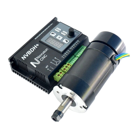
Novusun Manual of NVBDH+/NVBDL+ cnc.prom.ua » Chapter 1. Brief Introdution 1.1 Products brief introduction We design Brushless spindle driver NVBDH+ and NVBDL+ specialized for the ecomomic engraving machine,it matchs with the brushless DC motor.With the updated DSP technology,the driver can drive the motor to output more precise speed and bigger torque comparing with current drivers.We adopt the idea from the inverter, designed independent demountable panel.The users can take down the panel from the main driver and install it on the controller cabinet.By the panel,we can set the parameter,control motor speed and... - Page 4 Novusun Manual of NVBDH+/NVBDL+ cnc.prom.ua 9) Speed testing port for user to inspect the real speed. 10) Internal over-voltage, over-current and stalling inspection 11) Input signal TTL compatible 1.3 Product appearance and dimension NVBDH+ product appearance pls see picture 1-1,detached driver pls see picture 1-2,NVBDH with motor see picture 1-3.
- Page 5 Novusun Manual of NVBDH+/NVBDL+ cnc.prom.ua Figurei-2. detached NVBDH+ appearance Figurei-3. NVBDH with brushless spindle motor as one set...
- Page 6 Novusun Manual of NVBDH+/NVBDL+ cnc.prom.ua Figurei-4. NVBDL+ Product appearance B R U S H L E S S M OTOR DRIVER W ITHOUT HALL N V B D L + //Novusun # ¥ c n c r a & 1 R U | j^ S T O p j CW C CW PWM F G VSI GNO r r r I r I...
- Page 7 Figure1-6. NVBDL+ brushless spindle motor as one set NVBDH+ and NVBDL+ mechanical dimensions are the same,here we take NVBDL+ as example.Product outline dimension is 118*76*33mm,as picture 1-7 shows.The two installing hole size is 110mm,see picture 1-8.
- Page 8 Novusun Manual of NVBDH+/NVBDL+ cnc.prom.ua Figure1-8. back side installing hole dimension...
- Page 9 Novusun Manual of NVBDH+/NVBDL+ cnc.prom.ua 1.4 Notice and Waring Prohibit staying in the rain, it will cause short-circuit.. Pls use proper voltage power supply and motor. ▲ Note the power supply connection. Prohibit reverse connection of power supply and Hall.
-
Page 10: Chapter 2. Connection
Novusun Manual of NVBDH+/NVBDL+ cnc.prom.ua Connection » Chapter 2. 2.1 Connection interface definition NVBDL without Hall feedback,other parts are same as NVBDH. NVBDH+ and NVBDL+ connection table as table 2-1.The green color Hall signal cable is only for NVBDH+. Mark Definition Main power... - Page 11 Hall version NVBDH+: NVBDH+panel button speed control+ Panel start/stop control NVBDH+panel button speed control+ Panel start/stop control connection pls see picture 2-1.In this mode,if the control system need to collect motor speed data,then FG x GND port on NVBDH+ need to connect with signal collection port x GND port on controller.Cable thick...
- Page 12 BLACK HALL GND Figure2-1. NVBDH+panel button speed control+ Panel start/stop control 2^ NVBDH+ external analog speed control+external interface start/stop control NVBDH+ external analog speed control+external interface start/stop control connection pls see picture 2-2.The VSI is analog speed control interface,connect VSI to controller analog...
- Page 13 Novusun Manual of NVBDH+/NVBDL+ cnc.prom.ua Figure2-2. NVBDH+ external PWM speed control+external interface start/stop control 3 NVBDH+ external PWM speed control+external interface start/stop control NVBDH+ external PWM speed control+external interface start/stop control connection pls see the picture 2-3.In the mode of PWM control,connect PWM port on NVBDH+ to PWM output port on controller.
- Page 14 Novusun Manual of NVBDH+/NVBDL+ cnc.prom.ua Figure2-3. NVBDH+ external PWM speed control+external interface start/stop control 2.3 NVBDL+ connection NVBDL+ is the driver without Hall feedback,so the connection is easier than NVBDH+.Here we also introduce 3 control modes. К NVBDL+ panel button speed control+ Panel start/stop control NVBDL+ panel button speed control+ Panel start/stop control connection pls see the picture 2-4.
- Page 15 Novusun Manual of NVBDH+/NVBDL+ cnc.prom.ua Figure2-4. NVBDL+ panel button speed control+ Panel start/stop control connection 2^ NVBDL+ external analog speed control+external interface start/stop control NVBDL+ external analog speed control+external interface start/stop control connection see the picture 2-5. The VSI is analog speed control interface,connect VSI to controller analog output;CW and CCW control the motor rotating direction,CW and GND connect with motor CW.
- Page 16 Novusun Manual of NVBDH+/NVBDL+ cnc.prom.ua MAIN CONTROLLER Figure2-5. NVBDL+ external PWM speed control+external interface start/stop control 3^ NVBDL+ external PWM speed control+external interface start/stop control NVBDL+ external PWM speed control+external interface start/stop control connection pls see the picture 2-6.In the mode of PWM control,connect PWM port on NVBDL+ to PWM output port on controller.
-
Page 17: Configuration Methods
XVChapter 3 Configuration methods 3.1 Panel definition The parameters on NVBDH+ and NVBDL+ are the same, so here just describe only one.Panel definition reference image just see picture 3-1. Figure3 -1. control panel structure image M a r k D e fin itio n D e sc r ip tio n Start Press this button motor run... - Page 18 parameter uppage or increase parameter increase parameter speed control Motor speed adjust,CW increase speed,CCW reduce potentiometer speed. display parameter or motor running speed. LED display Chart 3-1 Control panel definition 3.2 Parameter setting and LED display 1 • . When power on buzzer “DI--”rings one time,and LED lights up, driver standby.
-
Page 19: Parameter Description
7^ At the standby page,press START button motor start to run,LED display the motor speed,real speed=display speed*10.For example,when LED display 1020,then the motor speed is 10200 R/Min.The LED 4 radixpoints take turns to flash,shows the motor run properly. 3.3 parameter description 1 Speed control mode P0 M a r k S p e ed co n tr o l m o d e... - Page 20 4^ PWM effective voltage P3 M a r k P W M e ffe c tiv e v o lta g e d e fa u lt =1 r e m a r k v a lu e Low level is effective, output 0V High level is effective, output DC5V 5 Panel start motor direction P4 M a r k...
Need help?
Do you have a question about the NVBDH+ and is the answer not in the manual?
Questions and answers