Table of Contents
Advertisement
Advertisement
Table of Contents

Subscribe to Our Youtube Channel
Related Manuals for Novusun CNC NVEMV2


Summary of Contents for Novusun CNC NVEMV2
- Page 1 MACH3 Ethernet Card NVEMV2 Manual...
-
Page 2: Table Of Contents
www.nvcnc.net Manual of NVEM 请在这里输入您的公司名称或产品名称 Contects Chapter 1. Introduction ..........................- 1 - 1.1 Product Introduction ..........................- 1 - 1.2 Products specification ..........................- 1 - 1.3 Products Appearance and size ........................ - 2 - 1.4 substantival explanation ......................... - 3 - 1.5 Noting and Waring .......................... -
Page 3: Chapter 1. Introduction
Brushless DC motor,Stepper motor driver,and also 1 to 6 aixs CNC motion controllers.。 NVEMV2.1 is the 3-6 axis motion controller we spend 4 years to design. NVEMV2.1 support Mach3 software and standard MPG,through Ethernet to communicate with computer,just use the Twine to connect directly or transfer with router. -
Page 4: Products Appearance And Size
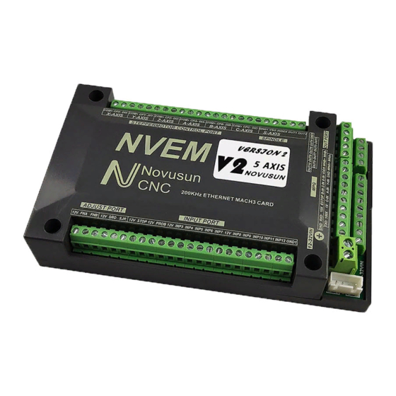
Compatible with MPG input,support the digital display MPG from our company。 1.3 Products Appearance and size NVEMV2.1 motion controller is with the sealed shell structure,there are 4pcs setting holes at the bottom.We can fix 4pcs 4mm diameter holes at the cabinet,and install the controller into the cabinet.The controller appearance as the Figure 1-1 and Figure 1-2 show:... -
Page 5: Substantival Explanation
Manual of NVEM Figure1-2. The other side of NVEMV2.1and installation dimensions 1.4 substantival explanation When operate the NVEM,where will be a lot of English abbreviation,now we list all of them for your kindly references: FRO:Feedingadjust:During the operating process,the F value already set,and need to adjust the current feeding speed, then we can adjust FRO value to realize it. - Page 6 Manual of NVEM Current Speed S#=setting S*SRO. SRJ:speed adjust manually During the operating process,as the manual speed already set,and we need to adjust the current speed,and impossible to fix the value during it is working,then we can revise the SRJ value to realize it.
-
Page 7: Noting And Waring
Manual of NVEM 1.5 Noting and Waring Free from exposure to the electronics without waterproof function.Please environment as dry as possible. This is the icon. Wiring warning, the IO input terminal of this equipment support the equipment with source switch (such as Inductive proximity switch.)When using such kind of switch, attention please: avoid the +terminal and –terminal of power supply to connect with GND.This equipment’s analogy quantity output terminal of spindlecontrolalos have a certain load capacity. -
Page 8: Chapter 2. Connection
www.nvcnc.net Manual of NVEM Chapter 2. Connection 2.1 Device Power supply Solution The power supply solution in the field of the Industrial automation is always very complicated,there is a lot of the GND,now we descript the structure of the power supply as below: The power supply structure as the Figure 2-1,main power supply input and MPG module and stepper control output module are common GND,Limited and Estop input module and Spindle speed adjust M3/M8/M1 module are common GND,between main power supply and output... -
Page 9: Product Connection Define And Method
www.nvcnc.net Manual of NVEM 2.2 Product connection define and method Figure2-2. Product wiring section and interface summary As the Figure 2-2 showed,the connection of the controller includes power supply interface,Ethernet connection interface,MPGinterface,Stepper/Servo control output interface,spindle control output interface, Estop and limited switch and tool setting input interface and so on. - Page 10 www.nvcnc.net Manual of NVEM Pin mark Axis Definition Commom+ common anode +5V COM+ X axis Pulse output- for X axis CPX- Directrion output- for X axis X axis DIX- Pulse output- for Y axis Y axis CPY- Directrion output- for Y axis Y axis DIY- Pulse output- for Z axis...
- Page 11 www.nvcnc.net Manual of NVEM Figure2-3. Stepper driver connection 2.2.2 Spindle control output We define the interface from left are: GND1(Output GND),VSO(0-10V adjustable speed output),INDEX(spindle speed feedback input),OUT1(common output port 1),OUT2(common output port 2),. Take Nowforeuer inverter as the example. Spindle control output and the inverter connection showed as Figure 2-4.If ACM and DCM are closed,only need to connect one port.
- Page 12 www.nvcnc.net Manual of NVEM Figure2-4. spindle control output and inverter connection VSO real output voltage=10V*s spindle setting speed/max spindle speed.Forexample,if max spindle speed is 24000,current spindle speed is S=18000,so the VSO output voltage=10*18000/24000=7.5V. Max. spindle speed setting ports as showed sa Figure 2-5,open it from Pulley from Menu config.The current spindle speed can be set by S directive or Mach 3 spindle setting speed module.
- Page 13 www.nvcnc.net Manual of NVEM 2.2.3 Common IO output interface Common IO output include OUT1,OUT2 on the spindle interface,totally 10 ports IO output,open drainoutput,internal structure as Figure 2-6: Figure2-6. OUT1-OUT10 internal structure Now just make a switch between OUTX(X=1-10) and GND,to control the relay output,theconection as the Figure 2-6.External power supply need to accord with the relay specification,the internal optocoupler GND open circuit only can absorb less than 50mA current,if relay absorb the current over 50mA,pls add current amplifier.In the Figure connect with OUT3,the...
- Page 14 www.nvcnc.net Manual of NVEM Figure2-7. OUTX connect with external relay method 2.2.4 MPG connection The MPG port totally have 18 wiring terminals, and the reference of eachwiring terminal definition is table 2-2. The reference of corresponding relation between system and MPG wiring is table 2-3 and table 2-4.
- Page 15 www.nvcnc.net Manual of NVEM 1 X multiplication short connect with means switch multiplication,cutoff means no pulse MPG Estop ESTOP short connect with means Estop effective,cutoff show invalid C Axis selected switch C-IN Short connect with GND meanas selecting C aixs,cutoff means don’t select B Axis selected switch B-IN Short connect with GND meanas selecting B...
- Page 16 www.nvcnc.net Manual of NVEM NVEM PIN No. MPG pin No. and color Estop 1multiplication 1 10multiplication 10 100multiplication 100 X100 X selecting Y selecting Z selecting A selecting B selecting C selecting A Phase + A Phase - B Phase + B Phase - 0V/CN/COM +5V-W...
- Page 17 www.nvcnc.net Manual of NVEM WHA+ green WHA- Black WHB+ white WHB- Black Table 2-4. Connection Between Single MPG and NVEM 2.2.5 Main power supply input Interface As the Figure 2-2 show,No. 5 position interface is the main power supply input,marked“+” is the power supply positive,the other one wasn’t marked is the negative,power supply voltage is 12-32VDC,Current must be not less then 1A.
- Page 18 www.nvcnc.net Manual of NVEM Figure2-8. Internal structure drawing of Input interface Figure2-9. Estop input connection - 16 -...
- Page 19 www.nvcnc.net Manual of NVEM Figure2-10. Tool Setting Connection Drawing 2 lines Proximity Switch/ordinary frettingswitch drawing see as Figure 2-11 Figure2-11. 2 lines Proximity Switch/ordinary frettingswitch drawing 3 lines Proximity Switch connection Figure 2-12,brown cable for Proximity switch connect with 12V,Black cable connect channel,blue cable connect with GND1. Only support PNP 3lines proximity switch.
- Page 20 www.nvcnc.net Manual of NVEM Figure2-12. PNP 3 lines Proximity Switch connection drawing 2.2.8 Parameter adjust interface By this adjust interface,user can use a muti-position switch and adigital potentionmeter(simple encoder) to modify FRO,SROand SJR.Wiring method see as figure2-13 simple encoder's COM A B connect to 12V/FHA/FHB,and muti-position switch connect to 12V SRO SJR.If 12Vdon't connect to SRO or SJR,current effective parameter is FRO, if 12V connect to SRO,current effective parameter is SRO,and if 12V connect to SJR current effective parameter is SJR.
- Page 21 www.nvcnc.net Manual of NVEM 2.2.9 Ethernet Port As the Figure 2-2 show,The marked No. 9 port is Ethernet communication port,NVEMcommunicate with mach 3 through it.Here we desgined 2 kinds communication mode,one is communication with network cable,one is communication with router,router is a better way to communicate,it won’t occupy the LAN port on PC,PC can control the NVEM and also can have the internet.
-
Page 22: Chapter 3. Software Installation
www.nvcnc.net Manual of NVEM Chapter 3. Software Installation 3.1 MACH3 Install MACH3 installation, registration, and USB plug-ins. See as Figure 3-1 Figure3-1. Mach3 soft installation First run the installation Mach3Version3.043.066 .Into the first page. See as Figure 3-2. - 20 -... - Page 23 www.nvcnc.net Manual of NVEM Figure3-2. MACH3 installation process 1 Click Next and then enter the page shown in Figure 3-3 Figure3-3. installation process Select I agree and click Next,See as Figure 3-4. - 21 -...
- Page 24 www.nvcnc.net Manual of NVEM Figure3-4. MACH3 installation process Select the installation path, click Next (it can be installed on any disk, and recommended to install the C drive or the D drive) See as Figure 3-5 Figure3-5. MACH3 installation process Click Next until completion.
-
Page 25: Mach3 Registration
www.nvcnc.net Manual of NVEM 3.2 MACH3 Registration Copy the file Mach1Lic.dat in The CD-ROM to mach3 installation path (eg C:/MACH3). 3.3 NVEM Plug-in installation Copy the file NVEM.dll to X:\Mach3\PlugIns , X is the disk where the soft is installed. - 23 -... -
Page 26: Chapter 4. Setting Of Software
www.nvcnc.net Manual of NVEM Chapter 4. Setting of software 4.1 Open software Double-click the mach3mill 。 Enter mach3 software. Pop-up the plug-in dialog box. See as Figure 4-1. Figure4-1. Plugin selection dialog Choose our plugin NVEM_Novusun-PlugIn---Ver- 2.0a Then press OK. If you do not want 。... -
Page 27: Software Common Settings
www.nvcnc.net Manual of NVEM connect successfully Figure4-2. 4.2 Software Common settings 4.2.1 Check NVEM plugin Click config plugins to input PluginConfig,you can seeNVEM. See as Figure4-4. Figure4-3. Input Config plugins - 25 -... - Page 28 www.nvcnc.net Manual of NVEM Figure4-4. MVEM Plugin 4.2.2 Motor operating parameters setting Figure4-5. Motor operating parameter setting menu entry See as Figure 4-5.From submenu “motor tuning” of the menu “config” into the motor parameter settings dialog. See as Figure 4-6 - 26 -...
- Page 29 www.nvcnc.net Manual of NVEM Figure4-6. Motor operating parameter settings dialog The parameters are defined as follows: teps per Pulse equivalent ,it is number of pulses required with axial movement 1mm, This : can be calculated by lead screw pitch and motor drive segment. Such as pitch 2.5mm,2-phase motor 8 segments, Calculation method is 8*200/2.5=640 。...
- Page 30 www.nvcnc.net Manual of NVEM Figure4-7. Port setting intry See as Figure 4- , 7 Click the sub-menu “ports and pins” of menu “Config” into Port Settings dialog box. Figure4-8. Pin&Port Dialog The sub-pages you need to set include “Motor Outputs”, “Input Signals”, “Output Signals” and “Spindle Setup”.First Click to enter “Motor Outputs”.
- Page 31 www.nvcnc.net Manual of NVEM To make the Z axis to the same direction, Z axis’s “Dir low” should be set to”√”.Other axes’s should be set as system need. Figure4-9. Stepper motor port settings dialog Click “Input Signals” Into the input signal settings page. See as Figure4-10 limited Input Settings dialog Figure4-10.
- Page 32 www.nvcnc.net Manual of NVEM Here you can configure according to your actual needs the corresponding function. Optional Function include XYZABC6axis’s Upper and lower limit 、 XYZABC6axis’s HOME point. Figure4-11. Estop Probe and index Setting dialog PROBE ESTOP and Spindle speed back index Setting see as Figure 4- , 、...
- Page 33 www.nvcnc.net Manual of NVEM Click “Spindle Setup” switch to the spindle settings page. See as Figure4-13. Spindle Settings dialog Figure4-13. Here we can configure the spindle rotates CW Reverse 、 CCW Mist Flood pin, See as 、 、 Figure4- , 13 They have been configured as 1 2 3 4.
- Page 34 www.nvcnc.net Manual of NVEM 4.2.4 MPG Settings First we have to choose the type of MPG, refer to figure 4-12, and enter the plug-in configuration page. NVMPG or standard MPG can be selected in the plug-in page. Figure 4-12 chooses the standard MPG by default Figure4-1.
- Page 35 www.nvcnc.net Manual of NVEM Figure4-2. Open MPG The third step is to change to MPG mode on the MPG panel , you can use the hand pulse, under the main page, click TAB to open MPG panel, refer to figure 4-14 Figure4-3.
-
Page 36: Chapter 5. Using Of Software
www.nvcnc.net Manual of NVEM Chapter 5. Using of software 5.1 Set Machine Coordinate system Firstly Open the software,as the drawing 5-1 shows,at this time,the software can operate the machine movements,but before the setting machine coordinate system,there is no connection between the software and machine.So first step is to set the machine coordinate system. Figure5-1. - Page 37 www.nvcnc.net Manual of NVEM orginal point direction, × means searching original point at negative direction; √ means searching original points at the positive direction.As the pincture 5-3 shows,X axis’s original position is at the negative direction,Y and Z’s original points are at the positive direction. Figure5-2.
-
Page 38: Set Workpiece Coordinate System
www.nvcnc.net Manual of NVEM As Figure 5-3 shows,this page also can set machine soft limit points,Soft Max is positive direction soft limited points,soft Min is negative direction soft limited points.The soft limited points values is according the references to the machine coordinate system,so as this example shows,Y and Z axis’s max value is 0,all the effective coordinate data is less than 0.As the Figure shows,according to our current request,we set our XYZ axis soft limited points area as [0,270] [-390,0] [-100,0]. - Page 39 www.nvcnc.net Manual of NVEM one or more workpiece coordinate system. 1 、 Move to current working piece 0 point Firstly hold down the material,use keyboard or pendant to move tool tip at the 0 point,so this 0 point is the working piece 0 point,it related with the working G code file,so the user must be very familiar to his own working G code.As our example shows,the 0 point is on the center of the working piece surface,so we just move the tool tip to this position.
-
Page 40: Open G Code File And Run
www.nvcnc.net Manual of NVEM Figure5-6. Main Screen after ZERO all axis 5.3 Open G code file and run As Figure 5-7 shows,press “load G code” botton at the main page or open “Load G code” at main menu “File”,open your G code.It displayed as Figure 5-8 showing,then press button “cycle start”... - Page 41 www.nvcnc.net Manual of NVEM Figure5-7. Press Load G-Code and open your G code Figure5-8. After opening G code,press “Cycle Start” and start to work - 39 -...
Need help?
Do you have a question about the NVEMV2 and is the answer not in the manual?
Questions and answers