Advertisement
Parts List
1
Power Commander
1
USB Cable
1
CD-ROM
1
Installation Guide
1
Power Adapter
2
Power Commander Decals
2
Dynojet Decals
2
Velcro
Strip
®
1
Alcohol Swab
The ignition MUST be turned
OFF before installation!
You can also download the Power
Commander software and latest maps
from our web site at:
www.powercommander.com
PLEASE READ ALL DIRECTIONS BEFORE STARTING INSTALLATION
Dynojet Research 2191 Mendenhall Drive North Las Vegas, NV 89081 (800) 992-4993 www.powercommander.com
i726-411
www.powercommander.com
2005 Benelli TNT 1130
I n s ta l l a t i o n I n s t r u c t i o n s
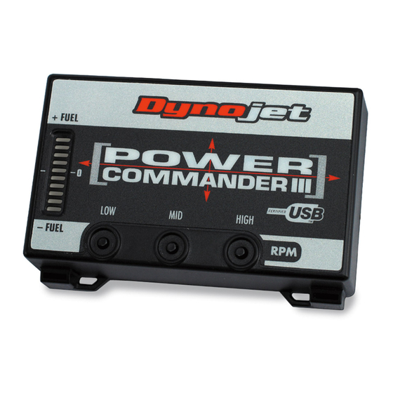
Button Adjustment Display
Faceplate Buttons
Expansion Port
2005 Benelli TNT 1130 - PCIII USB - 1
USB Port
Advertisement
Table of Contents

Related Manuals for Dynojet POWER COMMANDER III


Summary of Contents for Dynojet POWER COMMANDER III
- Page 1 Commander software and latest maps from our web site at: www.powercommander.com PLEASE READ ALL DIRECTIONS BEFORE STARTING INSTALLATION Dynojet Research 2191 Mendenhall Drive North Las Vegas, NV 89081 (800) 992-4993 www.powercommander.com i726-411 www.powercommander.com 2005 Benelli TNT 1130 - PCIII USB - 1...
- Page 2 Remove the seats Remove the fuel tank. Ground wire from PCIII Mount the Power Commander on top of the battery using the supplied vel- cro. Use the alcohol swab to clean both surfaces before attaching (Fig. A) Attach the ground wire of the PCIII to the negative side of the battery.
- Page 3 Plug the PCIII connectors in-line of the stock wiring harness and injectors (Fig. D). ORANGE - right cylinder YELLOW - middle cylinder GREEN - left cylinder Locate the Throttle Position Sensor connector. This is located on the right hand side of the throttle bodies (Fig.
Need help?
Do you have a question about the POWER COMMANDER III and is the answer not in the manual?
Questions and answers