Advertisement
1998-2003 Suzuki TLR1000
Parts List
1
Power Commander
1
USB Cable
1
CD-ROM
1
Installation Guide
1
Power Adapter
2
Power Commander Decals
2
Dynojet Decals
2
Velcro
Strip
®
1
Alcohol Swab
The ignition MUST be turned
OFF before installation!
You can also download the Power
Commander software and latest maps
from our web site at:
www.powercommander.com
PLEASE READ ALL DIRECTIONS BEFORE STARTING INSTALLATION
Dynojet Research 2191 Mendenhall Drive North Las Vegas, NV 89081 (800) 992-4993 www.powercommander.com
i303-411
www.powercommander.com
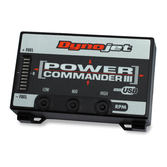
Installation Instructions
Button Adjustment Display
Faceplate Buttons
Expansion Port
USB Port
1998-2003 Suzuki TLR1000 - PCIII USB - 1
Advertisement
Table of Contents

Subscribe to Our Youtube Channel
Related Manuals for Dynojet Power Commander III


Summary of Contents for Dynojet Power Commander III
- Page 1 Commander software and latest maps from our web site at: www.powercommander.com PLEASE READ ALL DIRECTIONS BEFORE STARTING INSTALLATION Dynojet Research 2191 Mendenhall Drive North Las Vegas, NV 89081 (800) 992-4993 www.powercommander.com i303-411 www.powercommander.com 1998-2003 Suzuki TLR1000 - PCIII USB - 1...
- Page 2 Remove the main seat and the passen- ger seat or solo cover. Prop the fuel tank up using the prop rod in the tail section. Lay the PCIII in the tail section. Route the wiring harness from the PCIII wiring harness PCIII under the tail section and go towards the battery.
- Page 3 PCIII connectors Stock connectors Plug the connectors from the PCIII in- line of the stock wiring harness and throttle body harness (Fig. D). Unplug Locate the Throttle Position Sensor wiring harness. This harness has RED - GREY - BLACK/BROWN wires and is located on the left hand side of the throttle body.
- Page 4 Remove the battery access panel from the left hand fairing (Fig. G). Remove the battery cover. Route the ground wire from the PCIII down the left side of the engine to the battery. Attach the ground wire from the PCIII to the negative side of the battery (Fig.
Need help?
Do you have a question about the Power Commander III and is the answer not in the manual?
Questions and answers