Table of Contents
Advertisement
Quick Links
Advertisement
Table of Contents

Related Manuals for AXIOMTEK MVS100-323-FL


Summary of Contents for AXIOMTEK MVS100-323-FL
- Page 1 MVS100-323-FL Mini Fanless Vision System User’s Manual...
- Page 2 Disclaimers This manual has been carefully checked and believed to contain accurate information. Axiomtek Co., Ltd. assumes no responsibility for any infringements of patents or rights of any third party, or any liability arising from such use. Axiomtek does not warrant or assume any legal liability or responsibility for the accuracy, completeness or usefulness of any information in this document.
- Page 3 ◼ When handling boards and components, wear a grounding wrist strap available from most electronic component stores. Trademarks Acknowledgments Axiomtek is a trademark of Axiomtek Co., Ltd. ® Windows is a trademark of Microsoft Corporation. IBM, PC/AT, PS/2, VGA are trademarks of International Business Machines Corporation.
-
Page 4: Table Of Contents
Table of Contents Disclaimers ..................... ii ESD Precautions ................... iii Section 1 Introduction ..............1 General Description ................1 System Specifications ................ 2 1.2.1 Main CPU Board ..................2 1.2.2 I/O System ....................2 1.2.3 General Specification .................. 2 1.2.4 Vision I/O (12-pin terminal connetor) ............ - Page 5 3.1.2 Isolated Digital Output & Trigger Output ........... 28 I/O Connection (4-pin terminal connector) ........29 3.2.1 LED Lighting Control ................. 29 Section 4 Operating ..............31 Operating ................... 31 4.1.1 Trigger Input/ Output ................. 31 4.1.2 LED Lighting Control ................. 32 4.1.3 Interrupt .....................
- Page 6 This page is intentionally left blank.
-
Page 7: Section 1 Introduction
⚫ General Description The MVS100-323-FL is a mini fanless vision system that comes with an Intel® Atom® x5-E3940 processor. It integrates dual camera interfaces and special vision I/O features for machine vision applications, including GigE camera support, trigger input and output with microsecond-scale real-time control, as well as LED lighting output with constant current control to allow easy integration of any lighting source. -
Page 8: System Specifications
MVS100-323-FL User’s manual System Specifications 1.2.1 Main CPU Board ⚫ Intel® Atom® x5-E3940 processor (1.6GHz) ◼ Chipset ⚫ SoC integrated ◼ BIOS ⚫ AMI BIOS ◼ System memory ⚫ One DDR3L SO-DIMM, up to 8GB ◼ 1.2.2 I/O System ⚫... -
Page 9: Vision I/O (12-Pin Terminal Connetor)
MVS100-323-FL User’s manual 1.2.4 Vision I/O (12-pin terminal connetor) ⚫ Isolated digital input Number of channels: 2 ◼ Input type: wet contact: sink/source and dry contact ◼ Input level for dry contact: ◼ Close to ground (Logic 1), Open (Logic 0) Input level for wet contact: ◼... -
Page 10: Led Lighting Control (4-Pin Terminal Connetor)
MVS100-323-FL User’s manual 1.2.5 LED Lighting control (4-pin terminal connetor) ⚫ LED lighting control Number of channels: 2 ◼ Constant current control ◼ Operating mode: strobe and continuous mode ◼ LED output: 12/24VDC; Max. 0.5A per channel ◼ Delay time & duration time: 1 μs to 65ms; 1ms to 65s (time unit: 1us, 16bit/ 1ms,... -
Page 11: Dimensions
MVS100-323-FL User’s manual Dimensions Introduction... -
Page 12: I/O Outlet
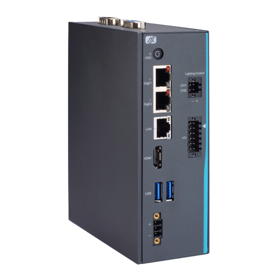
MVS100-323-FL User’s manual I/O Outlet The following figure shows you the I/O outlets on the front and rear panels of the MVS100. Introduction... -
Page 13: Packing List
The package bundled with your IMVS900 Series should contain the following items: MVS100 unit x 1 ⚫ Screw pack x 1 ⚫ Terminal block x 3 ⚫ DIN-rail kit x 1 ⚫ If you cannot find this package or any items are missing, please contact Axiomtek distributor immediately. Introduction... -
Page 14: Switch Settings & Wafer Connector
MVS100-323-FL User’s manual Switch Settings & Wafer connector Properly configure switch settings on the MVS100 to meet your application purpose. Below you can find a summary table of switch and onboard default settings. 1.6.1 AT/ATX Mode & Clear CMOS Optimal Defaults (SW1) If AT/ATX switch is set to AT mode, the system will be automatically powered on without pressing soft power button during power input;... -
Page 15: Wafer Connector For Optional Usb Dongle (Cn6)
MVS100-323-FL User’s manual 1.6.2 Wafer Connector for optional USB dongle (CN6) The wafer connector is used for the internal USB dongle. Connectors Connectors connect the board with other parts of the system. Loose or improper connection might cause problems. Make sure all connectors are properly and firmly connected. -
Page 16: Mini Card Slot
MVS100-323-FL User’s manual 1.7.1 Mini Card Slot The system has a PCI-Express Mini Card connector on the top side. It supports mSATA signals for storage. Pins Signals Pins Signals No use +3.3VSB No use No use +1.5V No use No use... -
Page 17: Lan
MVS100-323-FL User’s manual 1.7.2 The system has one RJ-45 connector: LAN. Ethernet connection can be established by plugging one end of the Ethernet cable into this RJ-45 connector and the other end (phone jack) to a 1000/100/10-Base-T hub. 1000 100/10... -
Page 18: Usb
MVS100-323-FL User’s manual 1.7.3 The Universal Serial Bus connectors are compliant with USB 3.2 Gen 1 (5Gb/s), ideal for connecting USB peripherals to the system, such as scanners, cameras and USB devices, etc. Signal USB Port 0 Signal USB Port 1... -
Page 19: Dc-In Power Connector
MVS100-323-FL User’s manual 1.7.5 DC-in Power Connector The system supports 24VDC DC-in connector for system power input. Pins Signals 1.7.6 HDMI Connector The HDMI (High-Definition Multimedia Interface) is a compact digital interface capable of transmitting high-definition video and high-resolution audio over a single cable. -
Page 20: Atx Power On/Off Button & Hdd Led Indicate
MVS100-323-FL User’s manual 1.7.7 ATX Power On/OFF Button & HDD LED Indicate The ATX power button is on the I/O side. It allows users to control MVS100 power on/off. LED Name Color Description Power When power is active, the system is in Orange standby mode. -
Page 21: 4-Pin Terminal Connector For Led Lighting Control
MVS100-323-FL User’s manual 1.7.8 4-Pin Terminal Connector for LED Lighting Control The 4-pin terminal connector supports 2CH LED output for a variety of illumination needs. Description Description LED1 + LED1 - LED2 + LED2 - 1.7.9 12-Pin Female I/O Connector The 12-pin I/O connector has special I/O functions, including trigger I/O, DIO. -
Page 22: Com
MVS100-323-FL User’s manual 1.7.10 The system has one serial port for peripheral communication. 1 port DB9 support RS-232/422/485 which can be selected by BIOS. ⚫ Supports auto flow control in RS485 mode. ⚫ Supports high speed mode115.2 Kbps, up to 1.5 Mbps ⚫... -
Page 23: Pd Power Indicator & Gige1 ~ Gige2 Ports
MVS100-323-FL User’s manual 1.7.11 PD Power Indicator & GigE1 ~ GigE2 ports The system has two camera interfaces with PoE functions for connecting industrial cameras. PD Power Indicator When a GigE port is currently active, its corresponding PD power indicator will light up. - Page 24 MVS100-323-FL User’s manual This page is intentionally left blank. Introduction...
-
Page 25: Section 2 Hardware Installation
MVS100-323-FL User’s manual Section 2 Hardware Installation The MVS100 is convenient for your various hardware configurations, including the memory module and PCI Express card module (mSATA for storage). Section 2 will show you how to install the hardware. Installing the Memory Module Step 1 Turn off the system. -
Page 26: Installing The Pci Express Mini Card
MVS100-323-FL User’s manual Installing the PCI Express Mini Card The MVS100-323-FL provides a PCI Express Mini Card slot for storage. Step 1 Turn off the system. Step 2 Disconnect the power connector. Step 3 Turn the system over to the left side to locate and unscrew the four screws. Then remove the cover. - Page 27 MVS100-323-FL User’s manual Step 5 Hold the mSATA storage at 30 degrees up from the horizontal direction and inset the golden finger into the slot until it is fully inserted. Step 6 Fix the mSATA storage onto the board with one screw.
-
Page 28: Installing An Internal Usb Dongle (Option)
MVS100-323-FL User’s manual Installing an internal USB dongle (Option) The MVS100 supports an internal USB2.0 slot for installing a software dongle. Step 1 Turn off the system. Step 2 Disconnect the power connector. Step 3 Turn the system over to the left side to locate and unscrew the screws; then open the cover. -
Page 29: Installing Dail-Rail Mounting
MVS100-323-FL User’s manual Installing Dail-rail mounting The MVS100-323-Fl provides DIN-rail Mount for installing as below: Step 1 Prepare the DIN-rail mount kit ready, including the screws and bracket. Step 2 Install the bracket and fasten all screws tight, as illustrated below. -
Page 30: Wall-Mount Bracket Kit (Option)
MVS100-323-FL User’s manual Wall-mount bracket kit (Option) Get the four truss head M4*6L screws from the optional wall-mount kit to fix the wall-mount kit. Step 1 Prepare the wall-mount kit ready, including screws and bracket. Step 2 Install the bracket and fasten all screws tight. - Page 31 MVS100-323-FL User’s manual Φ Note: R2 = Hardware Installation...
- Page 32 MVS100-323-FL User’s manual This page is intentionally left blank. Hardware Installation...
-
Page 33: Section 3 I/O Connection
MVS100-323-FL User’s manual Section 3 I/O Connection I/O Connection (12-pin terminal connector) Refer to this section to connect any cables between the system and other devices. Each of the following I/O figures illustrates their respective connection on the MVS100. 3.1.1 Isolated Digital Input &... -
Page 34: Isolated Digital Output & Trigger Output
MVS100-323-FL User’s manual Wet contact: 7.5K ohm Device Trigger input DI_COM/ Trigger input_COM 3.1.2 Isolated Digital Output & Trigger Output The figure shows how to connect an output channel to the system. If an external voltage of 5~30 VDC is applied to an isolated digital or trigger output channel, the current will flow from the external voltage source to the system. -
Page 35: I/O Connection (4-Pin Terminal Connector)
MVS100-323-FL User’s manual I/O Connection (4-pin terminal connector) The system offers 2 ports for LED output, as shown by the red box in the figure below. Refer to this section to connect any cables between the lighting control output and other LEDs. - Page 36 MVS100-323-FL User’s manual This page is intentionally left blank. I/O Connection...
-
Page 37: Section 4 Operating
MVS100-323-FL User’s manual Section 4 Operating Operating This section describes the operation of the MVS100 in detail. 4.1.1 Trigger Input/ Output Trigger input supports de-bounce filter function to help filter out environmental noise. The de-bounce filter defines the interval width for high/low signals. Signals of interval width less than the defined value will be filtered out. -
Page 38: Led Lighting Control
MVS100-323-FL User’s manual Invert ◼ Trigger source mode can be set as rising trigger or falling trigger. Trigger Source Trigger Output Delay Time Rising Trigger Trigger Source Trigger Output Delay Time Falling Trigger 4.1.2 LED Lighting Control LED lighting output can be set to use continuous, trigger or strobe mode. Also, based on a... -
Page 39: Application
MVS100-323-FL User’s manual Application This section shows a real use case in the machine vision field. 4.2.1 Scenario In this scenario, when an optical sensor detects objects passing down the production line, it will send trigger signals to notify the system. These signals trigger a camera to capture images. - Page 40 MVS100-323-FL User’s manual This page is intentionally left blank. Operating...
-
Page 41: Section 5 Ami Bios Utility
MVS100-323-FL User’s manual Section 5 AMI BIOS Utility The AMI UEFI BIOS provides users with a built-in setup program to modify basic system configuration. All configured parameters are stored in a 16MB flash chip to save the setup information whenever the power is turned off. This chapter provides users with detailed description about how to set up basic system configuration through the AMI BIOS setup utility. -
Page 42: Navigation Keys
MVS100-323-FL User’s manual Navigation Keys The BIOS setup/utility uses a key-based navigation system called hot keys. Most of the BIOS setup utility hot keys can be used at any time during the setup navigation process. These keys include <F1>, <F2>, <Enter>, <ESC>, <Arrow> keys, and so on. -
Page 43: Main Menu
MVS100-323-FL User’s manual Main Menu The first time you enter the setup utility, you will be in the Main setup screen. You can return to the Main setup screen by selecting the Main tab. System Time/Date can be set up as described below. -
Page 44: Advanced Menu
MVS100-323-FL User’s manual Advanced Menu The Advanced menu also allows users to set configuration of the CPU and other system devices. You can select any of the items in the left frame of the screen to go to the sub menus: ACPI Settings ►... - Page 45 MVS100-323-FL User’s manual ACPI Sleep State ⚫ Select the ACPI (Advanced Configuration and Power Interface) sleep state. Configuration options are Suspend Disabled and S3 (Suspend to RAM). The S3 option selects ACPI sleep state the system will enter when suspend button is pressed.
- Page 46 MVS100-323-FL User’s manual Trusted Computing ⚫ Select the Security Device Support to enable or disable the TPM function. AMI BIOS Utility...
- Page 47 MVS100-323-FL User’s manual CPU Configuration ⚫ This screen shows the CPU version and detailed information. ➢ Intel Virtualization Technology This item allows a hardware platform to run multiple operating systems separately and simultaneously, enabling one system to virtually function as several systems.
- Page 48 MVS100-323-FL User’s manual F81804 Super IO Configuration ⚫ Use this screen to select options for the F81804 Super I/O configuration and change the value of the selected option. A description of selected item appears on the right side of the screen.
- Page 49 MVS100-323-FL User’s manual ➢ Select Mode The default setting for Serial Port is RS-232 and this option also supports other settings, including RS-422 and RS-485. AMI BIOS Utility...
- Page 50 MVS100-323-FL User’s manual Hardware Monitor ⚫ This screen displays hardware health. AMI BIOS Utility...
- Page 51 MVS100-323-FL User’s manual SATA Configuration ⚫ This item allows the user to read the currently installed hardware configurations for the SATA ports shown in the SATA Configuration menu. During system bootup, BIOS will detect the present SATA devices automatically. ➢...
- Page 52 MVS100-323-FL User’s manual USB Configuration ⚫ USB configuration can be configured here by selecting and changing each item. A description of the selected item appears on the right side of the screen. ➢ Legacy USB Support Enables Legacy USB support. The AUTO option disables legacy support if no USB devices are connected.
- Page 53 MVS100-323-FL User’s manual PoE Configuration ⚫ The MVS100 provides two GbE ports with PoE function. PoE configuration can be set here by selecting and changing each item, including power budget setting, power status monitoring and each port on/off control. A description of the selected item appears on the right side of the screen.
- Page 54 MVS100-323-FL User’s manual This screen displays independent power budget setting per port and PoE power consumption. AMI BIOS Utility...
- Page 55 MVS100-323-FL User’s manual This screen shows each port’s on/off control settings and allows the user to monitor PoE connection status. AMI BIOS Utility...
-
Page 56: Chipset
MVS100-323-FL User’s manual Chipset This screen shows memory information. AMI BIOS Utility... -
Page 57: Security Menu
MVS100-323-FL User’s manual Security Menu The Security menu allows users to change the security settings for the system. ➢ Administrator Password This item indicates whether an administrator password has been set (installed or uninstalled). ➢ User Password This item indicates whether a user password has been set (installed or uninstalled). -
Page 58: Boot Menu
MVS100-323-FL User’s manual Boot Menu The Boot menu allows users to change boot options of the system. ➢ Setup Prompt Timeout Number of seconds to wait for setup activation key. 65535(0xFFFF) means indefinite waiting. ➢ Bootup NumLock State Use this item to select the power-on state for the keyboard NunLock. -
Page 59: Save & Exit Menu
MVS100-323-FL User’s manual Save & Exit Menu The Save & Exit menu allows users to load your system configuration with optimal or fail-safe default values. ➢ Save Changes and Exit When finishing the system configuration settings, select this option to leave Setup and return to Main Menu. - Page 60 MVS100-323-FL User’s manual ➢ Discard Changes and Reset Select this option to quit Setup without making any permanent changes to the system configuration and reboot the computer. Select Discard Changes and Reset from the Save & Exit menu and press <Enter>. Select Yes to discard changes and reset.
-
Page 61: Appendix A Watchdog Timer
MVS100-323-FL User’s manual Appendix A Watchdog Timer A.1 About Watchdog Timer After the system stops working for a while, it can be auto-reset by the watchdog timer. The integrated watchdog timer can be set up in the system reset mode by program. - Page 62 MVS100-323-FL User’s manual This page is intentionally left blank. Watchdog Timer...
Need help?
Do you have a question about the MVS100-323-FL and is the answer not in the manual?
Questions and answers