Grundfos Hydro Multi-E Series Installation And Operating Instructions Manual
Hide thumbs
Also See for Hydro Multi-E Series:
- Installation and operating instructions manual (54 pages) ,
- Installation and operating instructions manual (432 pages)
Table of Contents
Advertisement
Quick Links
Advertisement
Table of Contents

Related Manuals for Grundfos Hydro Multi-E Series


Summary of Contents for Grundfos Hydro Multi-E Series
- Page 1 GRUNDFOS INSTRUCTIONS Hydro Multi-E Installation and operating instructions...
-
Page 2: Table Of Contents
Setting the product (E products) Symbols used in this document 14.1 Setting by means of the pumps Warnings against hazards involving risk of death or 14.2 Setting by means of Grundfos GO Remote personal injury 14.3 Communication Other important notes 14.4... -
Page 3: Limited Warranty
Indicates a hazardous situation which, if not avoided, Products manufactured by GRUNDFOS PUMPS CORPORATION will result in death or serious personal injury. (Grundfos) are warranted to the original user only to be free of defects in material and workmanship for a period of 24 months WARNING from date of installation, but not more than 30 months from date of manufacture. -
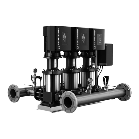
Page 4: Product Introduction
Depending on the size, the booster system is delivered in a wooden crate, closed wooden box, wrapped on a pallet that is Grundfos Hydro Multi-E pump systems are designed for pressure designed for transport by forklift truck or similar vehicle. -
Page 5: Identification
5. Identification When lifting the product, the lifting point must always 5.1 Nameplate be above the center of gravity to ensure stability. • Use lifting gear that ensures a vertical lift. Type: HYDRO MPC E 3CRE 15-03 • Use a safety strap around one of the pump motors to prevent Model: A 98919308 P1 01 05 52 the system from tilting. -
Page 6: Type Key
5.2 Type key Code Example Hydro Multi 2 CRE 15-02 3 x 460 V, 60 Hz Type range System type All pumps, E-motor Number of pumps with integrated frequency drive and pump type Number of fixed-speed pumps and pump type Supply voltage, frequency 6. -
Page 7: Drain Holes
90 ° to either side or 180 °. Use dedicated IT network motors if the pump system is supplied through an IT network. Contact Grundfos. The wires in the breaker cabinet must be as short as possible,... -
Page 8: Connection Terminals
• one analog output • two dedicated digital inputs • two configurable digital inputs or open-collector outputs • Grundfos Digital Sensor input and output • two Pt100/1000 inputs • two LiqTec sensor inputs • two signal relay outputs •... - Page 9 Fig. 9 Connection terminals, CRE pumps Supply to potentiometer +5 V and sensor Terminal Type Function Ground Normally closed Grundfos Digital Sensor GDS TX contact output Signal relay 1 Common Grundfos Digital Sensor (LIVE or PELV) GDS RX input Normally open...
-
Page 10: Signal Cables
• The wires in the motor terminal box must be as short as possible. 7. Optional bus communication via Grundfos CIM modules 7.1 Installing a Communication Interface Module Fig. 13 Removing the CIM cover DANGER 3. -
Page 11: Identification Of Functional Module
7. Connect the cable screens of the bus cables to earth via one of the earth clamps (fig. 16, A). You can identify the fitted module in one of the following ways: Grundfos GO Remote You can identify the functional module in the "Fitted modules" menu under "Status". -
Page 12: Startup
Hygiene Grundfos pressure pump systems are functionally tested by running water through the system. During the test, Grundfos continuously surveys the quality of the test water. Since it is not possible to completely drain and dry the system after the test, the system must be rinsed or flushed thoroughly before being used for drinking water applications, due to risk of bacteria growth. -
Page 13: Hydro Multi-E In System Without Inlet Pressure
Installation, proceed as Hydro Multi-E is now in automatic mode and ready for operation. follows: The standard settings can be changed using Grundfos Go 1. Confirm that Hydro Multi-E corresponds to the order and that Remote, see 11. Multimaster function or HMI300. -
Page 14: Hmi200
Fig. 23 Setpoint set to 43.5 psi (3 bar), constant-pressure and warnings. control mode Enables radio communication with Grundfos GO Remote and other products of the same type. Makes the pump ready for operation or starts and stops the pump. -
Page 15: Hmi300 (Graphical Display)
If a pump has been stopped by pressing , it can only be restarted by pressing The pump can also be stopped with Grundfos GO Remote or via a digital input set to "External stop". See section 16. Priority of... - Page 16 This menu shows the status of the pump Grundfos GO Remote or another pump, and system as well as warnings and the green indicator light in Grundfos Eye alarms. flashes. A note also appears in the pump Settings...
-
Page 17: Multimaster Function
Factory setting 12.2.4 Further settings See section 29. Factory settings. You can make further settings with Grundfos GO Remote. See 12.2 Operating mode section 11. Multimaster function. The operating modes are the operating conditions to which the pump system can be set by the user. -
Page 18: Control Mode
12.3 Control mode 12.4 Pipe-filling function Here you can choose between the different control modes. This function is typically used in pressure-boosting applications, and it ensures a smooth startup of systems with, for instance, 12.3.1 Constant pressure empty pipes. We recommend this control mode if the pump is to deliver a Startup takes place over two phases. -
Page 19: Stop Function
12.5 Stop function In start-stop operation, the pressure varies between the start and stop pressures. See fig. 34. You can set the "Low-flow stop function" to the following values: In "User-defined mode", ΔH is factory-set to 10 % of the actual •... -
Page 20: Controller
12.6 Controller Constant differential The pumps have a factory default setting of gain (K ) and integral temperature time (T However, if the factory setting is not the optimum setting, you can change the gain and the integral time: • Set the gain within the range of 0.1 to 20. -
Page 21: Operating Range
12.7 "Action" Operating range If the value exceeds a limit, you can set an action. You can select Set the operating range as follows: the following actions: • Set the minimum speed within the range of fixed minimum • No action speed to user-set maximum speed. -
Page 22: Proportional Pressure
Set the flow calculation operating hours. In certain applications, the requirement remains Connect Grundfos GO to each pump in the system (one at the constant for long periods and does not require all pumps to run. time) then select "Setting the proportional pressure" in the In such situations, pump changeover does not take place settings. -
Page 23: Description Of Functions For Pumps
If you want to set an analog input for other purposes, you can do Other parameter this manually. Electrical signal If you make the manual setting via Grundfos GO Remote, you need to enter the menu for the analog input under the "Settings" Select signal type: menu. -
Page 24: Pt100/1000 Inputs
13.2 Pt100/1000 inputs – a pressure switch installed on the inlet side of the pump – a float switch installed on the inlet side of the pump. Function • "Accumulated flow." The Pt100/1000 inputs can be set to these functions: When this function is selected, the accumulated flow can be •... -
Page 25: Digital Inputs/Outputs
13.4 Digital inputs/outputs Duration timer mode (only for input) Select the duration timer mode. See fig. 41. You can select if the interface is to be used as input or output. The output is an open collector and you can connect it to, for •... -
Page 26: Analog Output
13.6 "Analog output" • "Limit 1 exceeded" and "Limit 2 exceeded" The analog output enables the reading of certain operating data "Limit-exceeded function" to external control systems. Signal range Output not To set the analog output, make the settings below. [V, mA] Output active active... -
Page 27: External Setpoint Function
13.7 External setpoint function 13.7.1 "Setpoint influence" functions You can select the following functions: You can influence the setpoint with an external signal: • "Not active" • one of the analog inputs When set to "Not active", the setpoint is not influenced by any •... -
Page 28: Predefined Setpoints
4 are closed. If you compare with the table above, you can Grundfos GO Remote and wireless pump connection see that "Predefined setpoint 6" is activated. 1. Power on both pumps. 2. Establish contact to one of the pumps with Grundfos GO Digital input 4 Setpoint 7 Remote. -
Page 29: Setting The Product (E Products)
20. Press [Finish] in the "Setup complete" dialog box. Grundfos GO Remote enables setting of functions and gives 21. Wait for the green indicator light in the middle of Grundfos Eye access to status overviews, technical product information and to light up. -
Page 30: Menu Overview
14.4 Menu overview 14.4.1 Main menus Menu or function Menu or function available for system available for pump Dashboard ● ● Status ● ● Settings ● ● "Setpoint" ● "Operating mode" ● "Control mode" ● "Pipe filling function" ● "Buttons on product" ●... -
Page 31: Protective Functions
The system starts up automatically if it has been stopped due to installed. dry running. It can be changed to manual restart with Grundfos GO Remote. 15.1 Dry-running protection Hydro Multi-E must be protected against dry running. - Page 32 Common (LIVE or SELV) Supply to potentiometer Normally open +5 V and sensor contact Ground Grundfos Digital Sensor GDS TX output Grundfos Digital Sensor GDS RX input Analog input: 0-20 mA / 4-20 mA 0.5 - 3.5 V / 0-5 V / 0-10 V...
-
Page 33: Priority Of Settings
Min. speed Min. speed Start Start * If the bus communication is interrupted, the system will resume its previous operating mode, for example "Stop", selected on the control panel of the pump running as master or with Grundfos GO Remote. -
Page 34: Grundfos Eye
17. Grundfos Eye The operating condition of Hydro Multi-E is indicated by Grundfos Eye on the pump control panels. See fig. 53, pos. A. Fig. 53 Grundfos Eye Grundfos Eye Indication Description The power is off. No lights are on. -
Page 35: Signal Relays
The signal outputs can be set to "Operation", "Running", "Ready", "Alarm",or "Warning". The functions of the two signal relays are presented in the table below: Contact position for signal relays when activated Operating Description Grundfos Eye mode Operation Running Ready Alarm Warning Power off. -
Page 36: Digital Input
WARNING external system, for example a BMS or SCADA system. Crushing of feet For further information on CIM modules, see Grundfos Product Death or serious personal injury Center at www.grundfos.com, or contact Grundfos. - Wear appropriate protective gear, and use appropriate lifting equipment when dismantling the 21. -
Page 37: Fault Finding
Connect the power supply. c) The circuit breakers have cut out. Correct the fault and cut in the circuit breakers. d) The internal motor protection is activated. Contact Grundfos. e) The circuit breaker is defective. Replace the circuit breaker. The motor is defective. - Page 38 7. Leakage from a shaft seal. a) The shaft seal is defective. Replace the shaft seal. b) CRE and CRIE pumps: Re-adjust the shaft height. The height adjustment of the pump shaft is inaccurate. 8. There is noise when the a) The pumps are cavitating.
-
Page 39: Technical Data, Hydro Multi-E With Single-Phase Pumps
25. Technical data, Hydro Multi-E with 26. Technical data, Hydro Multi-E with single-phase pumps three-phase pumps 25.1 Supply voltage 26.1 Supply voltage 1 x 200-240 V ± 10 %, 50/60 Hz, PE. 3 × 200-240 V ± 10 %, 50/60 Hz, PE. Confirm that the supply voltage and frequency correspond to the Confirm that the supply voltage and frequency correspond to the values stated on the nameplate. -
Page 40: Leakage Current
1640 3281 4921 ambient temperatures between 122 and 140 °F (50 and 60 °C), Altitude [ft] oversized motors must be selected. Contact Grundfos for further information. Fig. 55 Supply voltage for three-phase motor in relation to altitude 27.1.3 Liquid temperature... -
Page 41: Minimum Inlet Pressure
In some regions, the pump system is available with a Ground reference (GND) low inlet manifold which makes it more suitable for All voltages refer to GND. suction lift operation. Contact Grundfos for further information. All currents return to GND. Absolute maximum voltage and current limits... - Page 42 Current signal ranges: Screened cable: 28-16 AWG (0.5 - 1.5 mm • 0-20 mADC, AU Grundfos Digital Sensor input and output (GDS) • 4-20 mADC, AL AU. Use Grundfos Digital Sensor only. Current signal: Ri is equal to 292 Ω.
-
Page 43: Factory Settings
29. Factory settings ● Function is enabled. ❍ Function is disabled. Function is not available. Settings "Setpoint" 30 % of sensor range "Operating mode" "Normal" "Control mode" "Constant pressure" "Pipe filling function" "Not active" "Buttons on product" "Active" "Stop function" (Low-flow stop function) "Active"... -
Page 44: Other Technical Data
[Hp (kW)] [dB(A)] environmentally sound way: 1. Use the public or private waste collection service. ● 0.49 - 1.4 2. If this is not possible, contact the nearest Grundfos company (0.37 - 1.1) ● or service workshop. ● 2.0 (1.5) ●... - Page 45 Phone: +1-905 829 9533 C.P. 66600 Apodaca, N.L Mexico Phone: +1-630-236-5500 Fax: +1-905 829 9512 Phone: +011-52-81-8144 4000 Fax: +1-630-236-5511 Fax: +011-52-81-8144 4010 www.grundfos.ca GRUNDFOS Kansas City www.grundfos.mx 9300 Loiret Blvd. Lenexa, Kansas 66219 Phone: +1-913-227-3400 Fax: +1-913-227-3500 www.grundfos.us Grundfos CBS Inc.
- Page 46 L-HME-TL-01 98419766 07.2020 ECM: 1284640 www.grundfos.com www.grundfos.us...
Need help?
Do you have a question about the Hydro Multi-E Series and is the answer not in the manual?
Questions and answers