Grundfos Hydro Multi-E Installation And Operating Instructions Manual
Hide thumbs
Also See for Hydro Multi-E:
Table of Contents
Advertisement
Advertisement
Table of Contents

Related Manuals for Grundfos Hydro Multi-E


Summary of Contents for Grundfos Hydro Multi-E
- Page 1 GRUNDFOS INSTRUCTIONS Hydro Multi-E Installation and operating instructions...
-
Page 2: Table Of Contents
Additional protection Indicates a hazardous situation which, if not avoided, could result in death or serious personal injury. Startup Hydro Multi-E in system with positive inlet pressure Hydro Multi-E in system without inlet pressure CAUTION Operating modes Indicates a hazardous situation which, if not avoided, 10.1 Normal operation... -
Page 3: Scope Of These Instructions
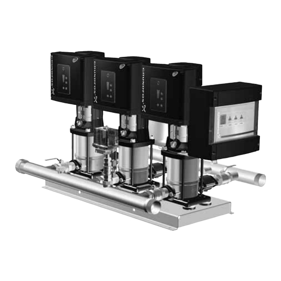
Tips and advice that make the work easier. 2. Scope of these instructions These installation and operating instructions apply to the Grundfos Hydro Multi-E booster systems. Hydro Multi-E is a range of factory-assembled booster systems, ready for installation and operation. 3. System sizing Breaker cabinet... -
Page 4: Type Key
6. Type key Example Hydro Multi CRIE 15-3 ABCDEF Name System type E: All pumps with E-motor Number of main pumps Pump type Voltage code U1: 3 x 380-415, N, PE, 50/60 Hz (three phase system with single-phase pumps) U2: 3 x 380-415, PE, 50/60 Hz U7: 1 x 200-240, PE, 50/60 Hz U8: 1 x 200-240, N, PE, 50/60 Hz UX: CSU variant (special voltage rating) -
Page 5: Operating Conditions
= Vapour pressure in metres head. = Safety margin of min. 0.5 metres head. Hydro Multi-E systems with CME pumps always require a positive inlet pressure, both during startup and operation. In some regions, the booster system is available with a low inlet manifold which makes it more suitable for suction lift operation. -
Page 6: Maximum Inlet Pressure
Observe the following to ensure adequate cooling of motor and electronics: Flow rate = 15 m • Position Hydro Multi-E in such a way that adequate cooling is NPSH ensured. (from page 23) = 1.2 metres head. • Keep motor cooling fins and fan blades clean. -
Page 7: Electrical Installation
Installation in building Breaker cabinet power supply. Fig. 6 Example of a mains-connected Hydro Multi-E with Carry out the earth connection as duplicate conductors. backup fuses and additional protection (applies only If the system cannot be installed with the supply disconnecting for systems with single-phase motors) device located minimum 0.6 m above service level according to... -
Page 8: Additional Protection
8.5 Additional protection 9. Startup 8.5.1 Systems with single-phase motors If Hydro Multi-E is connected to an electric installation where an Do not start the pumps until they have been filled earth leakage circuit breaker (ELCB) or ground fault circuit with liquid. -
Page 9: Hydro Multi-E In System Without Inlet Pressure
Hydro Multi-E is now in automatic mode and ready for operation. 16. Check that the pumps are cutting in and out, thus adjusting 9.2 Hydro Multi-E in system without inlet pressure the performance to the demand. -
Page 10: Operating Modes
Makes the pump ready for operation or power supply starts and stops the pump. If the power supply to Hydro Multi-E is disconnected, the settings Start: will be stored. The Hydro Multi-E will restart in the same If the button is pressed when the pump is operating condition as it was in before the disconnection. - Page 11 11.1.1 Setpoint setting Setting to maximum curve: • Press continuously to change over to the maximum curve Set the desired setpoint by pressing . The setpoint can of the pump (top light field flashes). When the top light field is be set on any of the pumps in the system and applies to the on, press for 3 seconds until the light field starts flashing.
-
Page 12: Grundfos Go Remote
If a pump has been stopped by pressing , it can only be restarted by pressing The pump can also be stopped with Grundfos GO Remote or via a digital input set to "External stop". See section 16. Priority of settings. -
Page 13: Menu Overview For Grundfos Go Remote
12.2 Menu overview for Grundfos GO Remote 12.2.1 Main menus Menu or function Menu or function available for system available for pump Dashboard ● ● Status ● ● Settings ● ● Setpoint ● Operating mode ● Control mode ● Pipe filling function ●... -
Page 14: Multi-Master Function
If it is not possible to remove the cause of the alarm on the master pump, another pump can function as master pump. Connect the outlet-pressure sensor to one of the other pumps and configure it with Grundfos GO Remote. The system can now be restarted. 13.2 Systems with two or more outlet-pressure... - Page 15 Common (LIVE or SELV) functional module (FM 300). Normally open Furthermore, the digital input must be configured with a Grundfos contact GO Remote to detect dry running. The system must be restarted manually if it has been stopped Normally closed due to dry running.
-
Page 16: Bus Signal
Example: If, via the digital input, the system has been set to maximum speed, the pump control panel or Grundfos GO Remote can only set the system to "Manual" or "Stop". -
Page 17: Grundfos Eye
17. Grundfos Eye The operating condition of Hydro Multi-E is indicated by Grundfos Eye on the pump control panels. See fig. 20, pos. A. Fig. 20 Grundfos Eye Grundfos Eye Indication Description Power off. No lights are on. The motor is not running. -
Page 18: Signal Relays
The signal outputs can be set to "Operation", "Running", "Ready", "Alarm" and "Warning". The functions of the two signal relays appear from the table below: Contact position for signal relays when activated Operating Description Grundfos Eye mode Operation Running Ready Alarm Warning Power off. -
Page 19: Digital Input
19. Digital input 21. Insulation resistance Hydro Multi-E has a digital input for external faults. The input has Do not measure the insulation resistance of motor been factory-set to external fault and will be active in closed windings or an installation incorporating motors with condition. -
Page 20: Fault Finding
Wait until the pressure has dropped, or lower the when started. equal to the setpoint set. pressure on the outlet side of Hydro Multi-E, and check that the booster system starts. b) The power supply is disconnected. Connect the power supply. -
Page 21: Technical Data, Hydro Multi-E With Single-Phase Pumps
25. Technical data, Hydro Multi-E with 27. Inputs and outputs single-phase pumps Ground reference (GND) All voltages refer to GND. 25.1 Supply voltage All currents return to GND. 3 x 380-415 V - 10 %/+ 10 %, 50/60 Hz, N, PE. -
Page 22: Other Technical Data
This product or parts of it must be disposed of in an environmentally sound way: 1. Use the public or private waste collection service. 2. If this is not possible, contact the nearest Grundfos company or service workshop. Subject to alterations. - Page 23 Appendix NPSH CR(I)E 1 CR(I)E 10 C R 1 , C R I 1 , C R N 1 C R 1 0 , C R I 1 0 , C R N 1 0 [ k P a ] [ m ] [ k P a ] [ m ]...
- Page 24 CME-A/-I 5 [kPa] 60 Hz 50 Hz Q [m³/h] Q [l/s] CME-A/-I 10 [kPa] 60 Hz 50 Hz Q [m³/h] Q [l/s] CME-A/-I 15 [kPa] 60 Hz 50 Hz 10 12 14 16 18 20 22 24 Q [m³/h] Q [l/s] Vapour pressure (°C)
- Page 25 Mi, Grundfos, izjavljujemo pod vlastitom odgovornošću da je proizvod Grundfos dichiara sotto la sua esclusiva responsabilità che i prodotti Hydro Multi-E, na koji se ova izjava odnosi, u skladu s direktivama ovog Hydro Multi-E, ai quali si riferisce questa dichiarazione, sono conformi Vijeća o usklađivanju zakona država članica EU:...
- Page 26 Applies only to water pumps marked with the minimum efficiency index MEI. See pump nameplate. This EC declaration of conformity is only valid when published as part of the Grundfos installation and operating instructions (publication number 98491894 0517). Bjerringbro, 7th April 2017...
- Page 27 3 бөлім: өнімнің фирмалық тақташасында орналасқан шығарылған уақыты жөніндегі мәлімет Сертификаттау туралы ақпарат: Hydro Multi-E типті сорғылары «Төмен вольтты жабдықтардың қауіпсіздігі туралы» (ТР ТС 004/2011), «Машиналар және жабдықтар қауіпсіздігі туралы» (ТР ТС 010/2011) «Техникалық заттардың электрлі магниттік сәйкестілігі» (ТР ТС 020/2011) Кеден Одағының техникалық регламенттерінің талаптарына сәйкес...
- Page 28 3-Бөлүк: жабдуунун фирмалык тактасында жайгашкан даярдоо мөөнөтү тууралуу маалымат. Шайкештик жөнүндө декларация Hydro Multi-E 2.2 түрүндөгү соргучтар Бажы Биримдиктин Техникалык регламенттин талаптарына ылайыктуу тастыкталган: ТР ТБ 004/2011 «Төмөн вольттук жабдуунун коопсуздугу жөнүндө»; ТР ТБ 010/2011 «Жабдуу жана машиналардын коопсуздугу жөнүндө»; ТР ТБ 020/2011 «Техникалык каражаттардын электрмагниттик...
- Page 29 Unit 1, Ground floor Turkey Av. Humberto de Alencar Castelo Branco, Siu Wai Industrial Centre GRUNDFOS Pumper A/S GRUNDFOS POMPA San. ve Tic. Ltd. Sti. 29-33 Wing Hong Street & Strømsveien 344 Gebze Organize Sanayi Bölgesi CEP 09850 - 300...
- Page 30 98491894 0517 ECM: 1173360 www.grundfos.com...
Need help?
Do you have a question about the Hydro Multi-E and is the answer not in the manual?
Questions and answers