Sign In
Upload
Manuals
Brands
Grundfos Manuals
Extender
Hydro Multi-E Series
Grundfos Hydro Multi-E Series Manuals
Manuals and User Guides for Grundfos Hydro Multi-E Series. We have
3
Grundfos Hydro Multi-E Series manuals available for free PDF download: Installation And Operating Instructions Manual
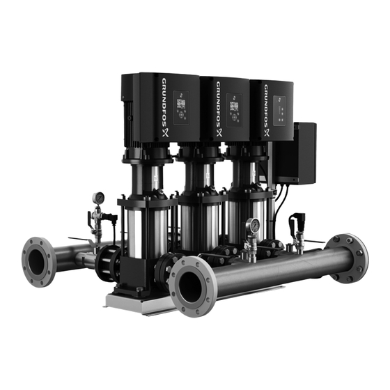
Grundfos Hydro Multi-E Series Installation And Operating Instructions Manual (432 pages)
Brand:
Grundfos
| Category:
Water Pump
| Size: 36 MB
Table of Contents
English
4
Table of Contents
4
Symbols Used in this Document
4
Scope of These Instructions
4
Identification
5
Type Key
5
Nameplate
5
Product Description
5
Hydro Multi-E
5
Functions
5
General Description
5
Operating Conditions
6
Relative Air Humidity
6
Maximum Operating Pressure
6
Shaft Seal Run-In
6
Minimum Inlet Pressure
6
Maximum Inlet Pressure
6
Minimum Flow Rate
6
Start/Stop
6
Diaphragm Tank
6
Temperatures
6
Electrical Installation, Hydro Multi-E with Single-Phase Pumps
7
Installation
7
Mechanical Installation
7
Location
7
Electrical Installation, Hydro Multi-E with Three-Phase Pumps
8
Emergency Operation (Optional)
9
Dry-Running Protection
10
Start-Up
11
Hydro Multi-E in System with Positive Inlet Pressure
11
Hydro Multi-E in System Without Inlet Pressure
11
Operating Modes
12
Normal Operation
12
Stop or Max. Operation
12
Operating Condition in Case of Disconnection of Power Supply
12
Other Settings
12
Setting Via the Control Panel
12
Setpoint Setting
12
Hydro Multi-E in Constant-Pressure Operation
12
Setting to Max. Curve Duty
13
Start/Stop
13
Setting Via the R100
14
Menu OPERATION
15
Menu STATUS
15
Menu INSTALLATION
16
Digital Input
17
Data Communication
17
Indicator Lights and Signal Relay
18
Shutdown
19
Service Kits
19
Frost Protection
19
Maintenance
19
Breaker Cabinet
19
Motors
19
Pumps
19
Insulation Resistance
19
Fault Finding
20
Inputs/Outputs
21
Technical Data, Hydro Multi-E with Three-Phase
21
Technical Data, Hydro Multi-E with Single-Phase Pumps
21
Leakage Current
21
Supply Voltage
21
Other Technical Data
22
Disposal
22
Deutsch
61
Verwendete Symbole
61
Allgemeines
62
Hauptfunktionen
62
Hydro Multi-E
62
Produktbeschreibung
62
Produktidentifikation
62
Typenschild
62
Typenschlüssel
62
Betriebsbedingungen
63
Einlaufphase der Gleitringdichtung
63
Max. Zul. Anzahl an Ein-/Ausschaltungen
63
Maximal Zulässiger Betriebsdruck
63
Maximal Zulässiger Zulaufdruck
63
Membrandruckbehälter
63
Mindestförderstrom
63
Mindestzulaufdruck
63
Relative Luftfeuchtigkeit
63
Zulässige Temperaturen
63
Aufstellung
64
Aufstellungsort
64
Elektrischer Anschluss einer Hydro Multi-E mit Einphasenmotoren
64
Montage
64
Elektrischer Anschluss einer Hydro Multi-E mit Drehstrommotoren
65
Notbetrieb (Optional)
66
Trockenlaufschutz
67
Achtung
68
Hydro Multi-E in Systemen mit Positivem Zulaufdruck
68
Hydro Multi-E in Systemen ohne Zulaufdruck
68
Inbetriebnahme
68
Betriebsart Stopp oder MAX
69
Betriebsarten
69
Hinweis
69
Normalbetrieb
69
Weiterbetrieb nach einer Unterbrechnung der Spannungsversorgung
69
Weitere Einstellungen
69
Ein/Aus
70
Einstellen des Betriebs mit MAX-Kennlinie
70
Einstellen des Sollwerts
70
Einstellungen über das Bedienfeld
70
Hydro Multi-E IM Konstantdruckbetrieb
70
Einstellungen über die R100
71
Beschreibung des Menüs BETRIEB
72
Beschreibung des Menüs STATUS
72
Beschreibung des Menüs INSTALLATION
73
Datenübertragung
74
Digitaleingang
74
Meldeleuchten und Melderelais
75
Außerbetriebnahme
76
Ersatzteilsätze
76
Isolationswiderstand
76
Motoren
76
Pumpen
76
Schaltkasten
76
Schutz vor Frosteinwirkung
76
Wartung
76
Störungsübersicht
77
Ableitstrom
78
Eingänge/Ausgänge
78
Technische Daten der Hydro Multi-E mit Dreiphasigen Pumpen
78
Technische Daten der Hydro Multi-E mit Einphasigen Pumpen
78
Versorgungsspannung
78
Entsorgung
79
Weitere Technische Daten
79
Español
118
Alcance de Estas Instrucciones
118
Símbolos Utilizados en Este Documento
118
Descripción del Producto
119
Descripción General
119
Funciones
119
Hydro Multi-E
119
Identificación
119
Nomenclatura
119
Placa de Características
119
Arranque/Parada
120
Caudal Mínimo
120
Condiciones de Funcionamiento
120
Humedad Relativa del Aire
120
Presión Máxima de Entrada
120
Presión Máxima de Funcionamiento
120
Presión Mínima de Entrada
120
Rodaje del Cierre del Eje
120
Tanque de Diafragma
120
Temperaturas
120
Instalación
121
Instalación Eléctrica del Sistema Hydro Multi-E con Bombas Monofásicas
121
Instalación Mecánica
121
Ubicación
121
Instalación Eléctrica del Sistema Hydro Multi-E con Bombas Trifásicas
122
Funcionamiento de Emergencia (Opcional)
123
Protección contra Funcionamiento en Seco
124
Puesta en Marcha
125
Sistema Hydro Multi-E en Sistema con Presión de Entrada Positiva
125
Sistema Hydro Multi-E en Sistema sin Presión de Entrada
125
Configuración del Punto de Ajuste
126
Configuración Mediante el Panel de Control
126
Estado de Funcionamiento en Caso de Desconexión del Suministro Eléctrico
126
Funcionamiento Normal
126
Modos de Funcionamiento
126
Otros Ajustes
126
Parada O Funcionamiento Máximo
126
Sistema Hydro Multi-E en Funcionamiento con Presión Constante
126
Ajuste en la Curva Máxima de Trabajo
127
Arranque/Parada
127
Configuración Mediante el Control Remoto R100
128
Menú ESTADO
129
Menú FUNCIONAMIENTO
129
Menú INSTALACIÓN
130
Comunicación de Datos
131
Entrada Digital
131
Luces Indicadoras y Relé de Señal
132
Apagado
133
Bombas
133
Cuadro de Control
133
Kits de Reparación
133
Mantenimiento
133
Motores
133
Protección contra Heladas
133
Resistencia del Aislamiento
133
Localización de Averías
134
Corriente de Pérdidas
135
Datos Técnicos, Sistema Hydro Multi-E con Bombas Monofásicas
135
Datos Técnicos, Sistema Hydro Multi-E con Bombas Trifásicas
135
Entradas/Salidas
135
Tensión de Alimentación
135
Eliminación
136
Otros Datos Técnicos
136
Français
137
Symboles Utilisés Dans Cette Notice
137
Description du Produit
138
Description Générale
138
Désignation
138
Fonctions
138
Hydro Multi-E
138
Identification
138
Plaque Signalétique
138
Conditions de Fonctionnement
139
Débit Mini
139
Fonctionnement de la Garniture Mécanique
139
Humidité Relative de L'air
139
Marche/Arrêt
139
Pression D'entrée Maxi
139
Pression D'entrée Mini
139
Pression de Service Maxi
139
Réservoir à Membrane
139
Températures
139
Connexion Électrique, Hydro Multi-E Équipé de Pompes Monophasées
140
Installation
140
Installation Mécanique
140
Lieu D'installation
140
Connexion Électrique, Hydro Multi-E Équipé de Pompes Triphasées
141
Fonctionnement de Secours (Option)
142
Protection Contre la Marche à Sec
143
Hydro Multi-E Avec Pression D'entrée Positive
144
Hydro Multi-E Dans le Système Sans Pression D'entrée
144
Mise en Route
144
Autres Réglages
145
Condition de Fonctionnement en cas de Déconnexion de L'alimentation Électrique
145
Fonctionnement Arrêt ou Max
145
Fonctionnement Normal
145
Hydro Multi-E en Fonctionnement Pression Constante
145
Modes de Fonctionnement
145
Réglage du Point de Consigne
145
Réglage Via le Panneau de Commande
145
Marche/Arrêt
146
Réglage Sur la Courbe Maxi
146
Réglage Via le R100
147
Menu ETAT
148
Menu FONCTIONNEMENT
148
Menu INSTALLATION
149
Communication des Données
150
Entrée Numérique
150
Voyants Lumineux et Relais de Signal
151
Coffret de Commande
152
Kits de Maintenance
152
Maintenance
152
Mise Hors Service
152
Moteurs
152
Pompes
152
Protection Contre le Gel
152
Résistance D'isolement
152
Grille de Dépannage
153
Caractéristiques Techniques, Hydro Multi-E Équipé de Pompes Monophasées
154
Caractéristiques Techniques, Hydro Multi-E Équipé de Pompes Triphasées
154
Courant de Fuite
154
Entrées/Sorties
154
Tension D'alimentation
154
Autres Caractéristiques Techniques
155
Mise au Rebut
155
Русский
310
Значение Символов И Надписей В Документе
310
Область Применения Настоящих Инструкций
310
Hydro Multi-E
311
Обозначение
311
Общие Сведения
311
Описание Изделия
311
Расшифровка Типового Обозначения
311
Фирменная Табличка
311
Функции
311
Диапазон Температур
312
Максимальное Давление Подпора
312
Максимальное Рабочее Давление
312
Мембранный Напорный Гидробак
312
Минимальное Давление Подпора
312
Минимальный Расход
312
Обкатка Уплотнения Вала
312
Относительная Влажность Воздуха
312
Пуск/Останов
312
Условия Эксплуатации
312
Монтаж
313
Подключение Электрооборудования Hydro Multi-E С Однофазными Насосами
313
Расположение
313
Установка
313
Подключение Электрооборудования Hydro Multi-E С Трёхфазными Насосами
314
Работа В Аварийном Режиме (Дополнительно)
315
Защита От Сухого Хода
316
Hydro Multi-E В Системе Без Подпора
317
Hydro Multi-E В Системе С Подпором
317
Ввод В Эксплуатацию
317
Настройка Заданного Значения
318
Настройка С Помощью Панели Управления
318
Нормальный Режим
318
Прочие Установочные Значения
318
Режим Отключения Или Максимальный Режим
318
Режим Работы Hydro Multi-E При Постоянном Давлении
318
Режимы Эксплуатации
318
Условия Эксплуатации В Случае Прерывания Электропитания
318
Эксплуатации
318
Макс. Характеристикой
319
Настройка Рабочего Режима В Соответствии С
319
Пуск/Остановка
319
Настройка Параметров С Помощью Пульта R100
320
Меню СОСТОЯНИЕ
321
Меню ЭКСПЛУАТАЦИЯ
321
Меню УСТАНОВКА
322
Вход Цифрового Сигнала
323
Сигнализация Через Шину Связи
323
Светодиоды Системы Световой Индикации И Реле Системы Сигнализации
324
Защита От Замерзания
325
Испытание Изоляции На Пробой
325
Насосы
325
Отключение
325
Панель Управления И Блок Предохранителей
325
Сервисные Комплекты
325
Уход И Техническое Обслуживание
325
Электродвигатели
325
Таблица Обнаружения И Устранения Неисправностей
326
Входы/Выходы
327
Напряжение Питания
327
Технические Данные Hydro Multi-E С Однофазным Электродвигателем
327
Технические Данные Hydro Multi-E С Трехфазным Электродвигателем
327
Ток Утечки На Землю
327
Гарантии Изготовителя
328
Прочие Технические Данные
328
Утилизация Отходов
328
Advertisement
Grundfos Hydro Multi-E Series Installation And Operating Instructions Manual (54 pages)
Brand:
Grundfos
| Category:
Extender
| Size: 12 MB
Table of Contents
Table of Contents
2
1 Symbols Used in this Document
3
Warnings against Hazards Involving Risk of Death or Personal Injury
3
Other Important Notes
3
2 Product Introduction
3
Product Description
3
Intended Use
3
3 Receiving the Product
4
Transporting the Product
4
Inspecting the Product
4
Scope of Delivery
4
Handling and Lifting the Product
4
4 Identification
5
Nameplate
5
5 Type Key
6
6 Installation
7
Location
7
Mechanical Installation
7
Drain Holes
7
Electrical Installation
8
Mains Supply
8
Additional Protection
9
Connection Terminals
9
Signal Cables
13
7 Optional Bus Communication Via Grundfos CIM Modules
13
Installing a Communication Interface Module
13
8 Identification of Functional Module
14
9 Startup
15
Hygiene
15
Hydro Multi-E in System with Positive Inlet Pressure
15
Hydro Multi-E in System Without Inlet Pressure
16
10 User Interfaces
16
Standard Control Panel
16
Advanced Control Panel
18
11 Multimaster Function
19
Systems with Two or more Outlet-Pressure Sensors
19
12 Description of Functions for the System
19
Settings
19
Operating Mode
19
Control Mode
20
Pipe-Filling Function
20
Stop Function
21
Controller
22
Operating Range
23
Limit-Exceeded Function
23
Proportional Pressure
24
Pump Changeover
24
Undo
24
Pump Name
24
Unit Configuration
24
13 Description of Functions for Pumps
25
Analog Inputs
25
Pt100/1000 Inputs
26
Digital Inputs
26
Digital Inputs/Outputs
27
Signal Relays" 1 and 2 ("Relay Outputs")
28
Analog Output
28
External Setpoint Function
29
Predefined Setpoints
30
Alarm Log
30
Warning Log
30
Multi-Pump Setup
30
14 Setting the Product (E Products)
31
Setting by Means of the Pumps
31
Setting by Means of Grundfos GO Remote
31
Communication
31
Menu Overview for Grundfos GO Remote
32
15 Protective Functions
33
Dry-Running Protection
33
16 Priority of Settings
35
17 Grundfos Eye
36
18 Signal Relays
37
19 Digital Input
38
20 Data Communication
38
21 Maintenance
38
Pumps
38
Motors
38
Breaker Cabinet
38
Service Kits
38
22 Taking the Product out of Operation
38
Frost Protection
38
23 Startup the Product after Standstill
38
24 Fault Finding
39
25 Technical Data, Hydro Multi-E with Single-Phase Pumps
40
Supply Voltage
40
Leakage Current
40
Torques
40
26 Technical Data, Hydro Multi-E with Three-Phase Pumps
40
27 Operating Conditions
40
Temperatures
40
Installation Altitude
41
Humidity
41
Maximum Operating Pressure
41
Minimum Inlet Pressure
41
Maximum Inlet Pressure
42
Minimum Flow Rate
42
Maximum Starts and Stops
42
Diaphragm Tank
42
28 Inputs and Outputs
42
29 Factory Settings
44
30 Other Technical Data
45
31 Sound Pressure Level
45
Hydro Multi-E with Single-Phase Pumps
45
Hydro Multi-E with Three-Phase Pumps
45
32 Disposal
45
Grundfos Hydro Multi-E Series Installation And Operating Instructions Manual (46 pages)
Brand:
Grundfos
| Category:
Water Pump
| Size: 11 MB
Table of Contents
Table of Contents
2
1 Limited Warranty
3
2 Symbols Used in this Document
3
Warnings against Hazards Involving Risk of Death or Personal Injury
3
Other Important Notes
3
3 Product Introduction
4
Product Description
4
Intended Use
4
4 Receiving the Product
4
Transporting the Product
4
Inspecting the Product
4
Scope of Delivery
4
Handling and Lifting the Product
4
5 Identification
5
Nameplate
5
Type Key
6
6 Installation
6
Location
6
Mechanical Installation
6
Drain Holes
7
Electrical Installation
7
Mains Supply
7
Connection Terminals
8
Signal Cables
10
7 Optional Bus Communication Via Grundfos CIM Modules
10
Installing a Communication Interface Module
10
8 Identification of Functional Module
11
9 Startup
12
Drinking Water Systems
12
Hydro Multi-E in System with Positive Inlet Pressure
12
Hydro Multi-E in System Without Inlet Pressure
13
10 User Interfaces
13
Hmi200
14
HMI300 (Graphical Display)
15
11 Multimaster Function
17
Systems with Two or more Outlet-Pressure Sensors
17
12 Description of Functions for the System
17
Settings
17
Operating Mode
17
Control Mode
18
Pipe-Filling Function
18
Stop Function
19
Controller
20
Operating Range
21
Limit-Exceeded Function
21
Proportional Pressure
22
Pump Changeover
22
Undo
22
Pump Name
22
Unit Configuration
22
13 Description of Functions for Pumps
23
Analog Inputs
23
Pt100/1000 Inputs
24
Digital Inputs
24
Digital Inputs/Outputs
25
Signal Relays 1 and 2 ("Relay Outputs")
25
Analog Output
26
External Setpoint Function
27
Predefined Setpoints
28
Alarm Log
28
Warning Log
28
Multi-Pump Setup
28
14 Setting the Product (E Products)
29
Setting by Means of the Pumps
29
Setting by Means of Grundfos GO Remote
29
Communication
29
Menu Overview
30
15 Protective Functions
31
Dry-Running Protection
31
16 Priority of Settings
33
17 Grundfos Eye
34
18 Signal Relays
35
19 Digital Input
36
20 Data Communication
36
21 Maintenance
36
Pumps
36
Motors
36
Breaker Cabinet
36
Service Kits
36
22 Taking the Product out of Operation
36
Frost Protection
36
23 Startup the Product after Standstill
36
24 Fault Finding
37
25 Technical Data, Hydro Multi-E with Single-Phase Pumps
39
Supply Voltage
39
Leakage Current
39
Torques
39
26 Technical Data, Hydro Multi-E with Three-Phase Pumps
39
Leakage Current
40
Torques
40
27 Operating Conditions
40
Temperatures
40
Installation Altitude
40
Humidity
40
Maximum Operating Pressure
40
Minimum Inlet Pressure
41
Maximum Inlet Pressure
41
Minimum Flow Rate
41
Maximum Starts and Stops
41
Diaphragm Tank
41
28 Inputs and Outputs
41
29 Factory Settings
43
30 Other Technical Data
44
31 Sound Pressure Level
44
Hydro Multi-E with Single-Phase Pumps
44
Hydro Multi-E with Three-Phase Pumps
44
32 Disposal
44
Advertisement
Advertisement
Related Products
Grundfos Hydro Multi-B
Grundfos Hydro Solo-S CR Series
Grundfos Hydro Multi-E
Grundfos Hydro Multi-B Series
Grundfos Hydro Multi-S
Grundfos Hydro Multi-B CME
Grundfos Hydro Multi-B CR
Grundfos Hydro Multi-B CM
Grundfos Hydro Multi-E CRE
Grundfos Hydro Multi-E CME
Grundfos Categories
Water Pump
Control Unit
Industrial Equipment
Controller
Engine
More Grundfos Manuals
Login
Sign In
OR
Sign in with Facebook
Sign in with Google
Upload manual
Upload from disk
Upload from URL